

Page 1
HAWK ENTERPRISES OF ELKHART, INC
To Order Parts Call 1-888-702-5326 - https://monsterfloorequipmentparts.com
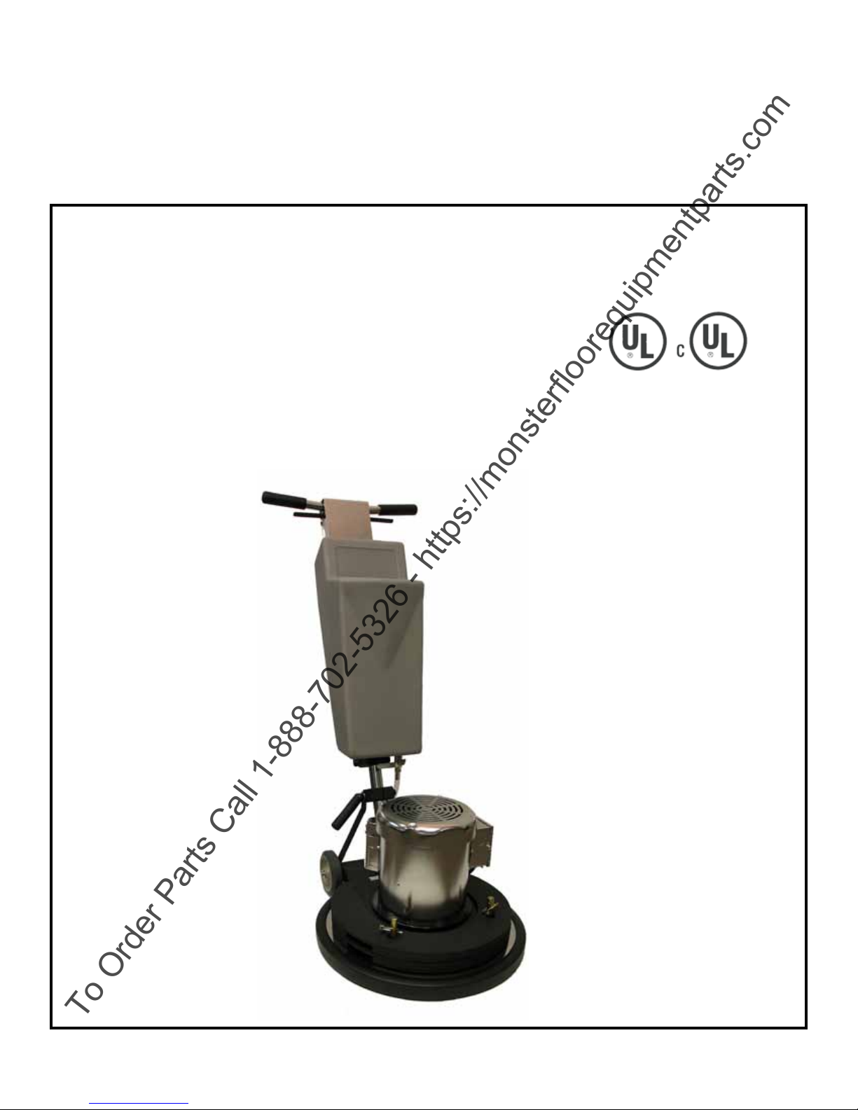
E-Glide Electro Roto Commercial
Floor Machine Owner’s Manual
Operation l Care l Service
Stock No. AR517 -- 17” (120V)
AR520 -- 20” (120V)
AR517- 230 - 17” (230V)
AR520 - 230 - 20” (230V)
Shown with Optional
Weight Kit
AR0032-KIT
Manual No.: AR520
Rev. 02 (09-2012)
Page 2

E-Glide Electro Roto
To Order Parts Call 1-888-702-5326 - https://monsterfloorequipmentparts.com
Table of Contents
Page
I. Specications……………………………………………………………………...2
II. Rules for Safe Operations………………………………………………………....3
Safety Recommendations………………………………………………………....3
Grounding Instructions……………………………………………........................4
III. Operating Instructions………………………………………………………….…5
IV. Preventative Maintenance Guide..........................................................................8-9
V. Troubleshooting Guide…………………………………………………………..10
VI. Repair Guide…………………………………………………………….……12-14
VII. Parts List
A. Base Assembly and Parts………………………………………………….…16
B. Handle Assembly and Parts………………………………………………19-20
C. Motor Assembly and Parts……………………………………… …………..18
D. Electro Valve Assembly and Parts……………………………………….…..17
E. Assembly Parts (Solution Tank Assembly)…………………………………..-22
F. 50 Foot Cord Assembly………………………………………………………23
G. Wiring Diagram………………………………………………………..…..…21
VIII. Warranty…………………………………………………………………………24
I
Page 3
E-Glide 17” and 20” Electro Roto Section I
To Order Parts Call 1-888-702-5326 - https://monsterfloorequipmentparts.com
Owner’s Manual
-- For Commercial Use -- Specications
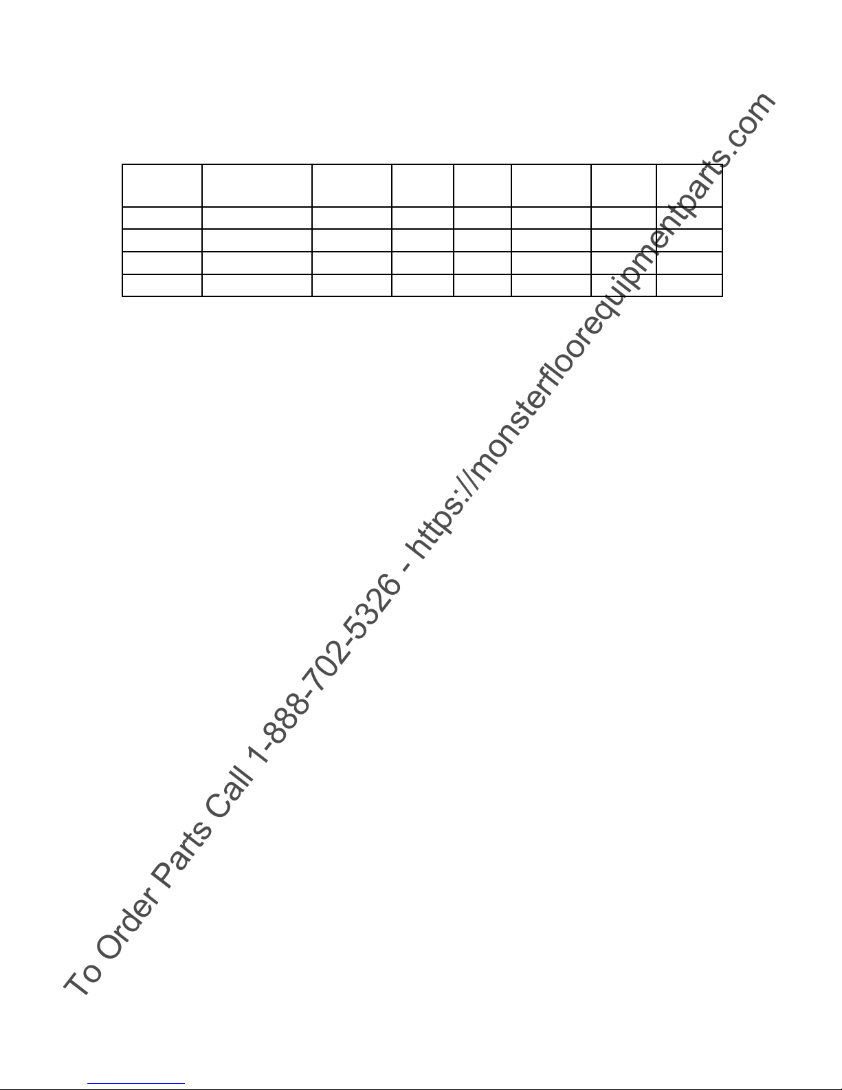
MODEL
516L AR517 165 17” 1 1/2 14.9 115 60
507L AR520 165 20” 1 1/2 14.9 115 60
MOTOR: AC, capacitor start/capacitor run (180 frame, TEFC) 1 1/2 HP Single-phase,
constant duty Heat Rise: 40 degrees Celsius
GEARBOX: Planetary type with 3 idler gears, 11:1 ratio heat treated harden gears/grease
lubricant sealed in unit for continuous use. Solid Steel coupling with steel
collar provides for engagement between gearbox and motor.
BASE: Heavy gauge epoxy coated steel frame, heavy gauge chrome plated brush
cover, 5 inch xed ball bearing wheels.
STOCK
NUMBER
AR517-230 165 17” 1 1/2 7.5 230 60
AR520-230 165 20” 1 1/2 7.5 230 60
BRUSH
RPM
SIZE H.P.
LOAD
AMPS
VOLTS Hz
HANDLE: All welded chrome plated steel construction using 1-3/8 inch diameter handle
tube. Left or right hand operation of switch levers with safety lock to prevent
accidental starting.
CORD: 50 foot, 12-3 ST safety yellow extension cord.
CORD Lower hook has provision for hanging a driving assembly or brush by its
HOOK: clutch plate.
SOLUTION Polyethylene construction for chemical resistance with
TANK: nger touch-controlled ow through Electro Valve.
WEIGHT: E-Glide 17” Electro Roto 122 lbs.
E-Glide 20” Electro Roto 132 lbs.
SHIPPING E-Glide 17” Electro Roto 133 lbs (Includes pad driver)
WEIGHT: E-Glide 20” Electro Roto 143 lbs (Includes pad driver)
2
Page 4
E-Glide 17” and 20” Electro Roto Section II
To Order Parts Call 1-888-702-5326 - https://monsterfloorequipmentparts.com
Owner’s Manual Rules For Operation
RULES FOR SAFE OPERATION
1. Give complete and undivided attention to the job at hand.
2. Never operate a roto unless handle is properly locked (See Operation Instructions).
3. Never operate a roto with a damaged cord.
4. When learning to operate a roto, choose an open area where there are no people close by.
5. Never use the driving assembly without a maintenance disc.
6. Attach the disc driving assembly by hand. Never “jump start.”
7. If the roto should start vibrating, stop it immediately and check for damaged or loose parts or non-concentric pad or at
spot on pad.
8. Never leave a roto unattended without rst unplugging plug from wall.
9. Do not operate the roto when moisture is suspected to have entered the motor, the switches of electro valve
10. Never break the grounding prong off the wall plug.
11. Test tighten all screws, nuts, and bolts at frequent intervals to prevent damage or lost parts.
12. See Electrical Safety Precautions (next page)
REGLAS DE OPERACION DE SEGURIDAD
1. Prestar completa atención al trabajo que se esta realizando.
2. Nunca opere la máquina a menos de que la agarradera este debidamente asegurada. (vea el manual de instrucciónes)
3. Nunca opere la máquina con un cable dañado.
4. Cuando aprenda a manejar la máquina elija un área dónde la gente no se encuentre cerca.
5. Nunca opere la máquina sin el disco.
6. Ponga el disco de ensamblaje con la mano, nunca salte la carga.
7. Si la máquina comienza a vibrar, pare de inmediato y cheque algún daño, o partes sueltas o un disco no bien sentrado o
un espacio plano en la almohadilla.
8. Nunca deje la máquina sin atención primero desconectela de la toma de corriente.
9. Nunca opere la máquina si sospecha que la humedad a entrado en el motor, apaguela de inmediato.
10. Nunca rompa la conexión a tierra en el enchufe de la pared.
11. Apriete todos los tornillos. y pernos en intervalos frequentes para prevenir daño o perdida de partes.
12. También observe las precauciones de seguridad electrica. ( próxima página)
SAFETY RECOMMENDATIONS
Be Safe - Avoid Possible Hazards
1. Your Electro-Roto is equipped with a power switch designed for safe operation.
2. Never use any device to lock the power switch in the “ON” position.
3. Never operate a roto unless handle is properly locked.
4. To avoid hazardous conditions, do not use your machine in areas where FLAMMABLE AND/OR EXPLOSIVE
VAPORS OR DUST are present or on slippery oors.
5. Always disconnect the Elecrto-Roto from electrical outlet before servicing machine.
6. Use care to keep electrical supply cord from contacting the rotating disc or drive block.
7. Do not allow children or unauthorized personnel to play with unit. Do not leave Electro-Roto connected to an electrical
outlet when left unattended.
RECOMENDACIONES DE SEGURIDAD
TENGA CUIDADO - PARA EVITAR POSIBLES PELIGROS
1. Su máquina esta equipada con un switch de poder designado para una operación segura.
2. Nunca utilize ningún dispositivo para asegurar el switch cuando este encendido.
3. Nunca operé la máquina a menos de que la manija este propiamente asegurada.
4. Para evitar peligros, no use la máquina en áreas inamables y/o vapores explosivos o polvo presente o en pisos
resbalosos.
5. Siempre desconecte la máquina de la toma de corriente.
6. Tenga cuidado al mantener la electricidad, siempre provea el cable con el disco giratorio o disco de conducción.
7. No permita que los niños o personal no autorizado juege con la unidad. Nunca deje la máquina conectada a la toma de
corriente y no la deje sin atención.
3
Page 5
GROUNDING INSTRUCTIONS
To Order Parts Call 1-888-702-5326 - https://monsterfloorequipmentparts.com
This appliance must be grounded. If it should electrically malfunction, grounding provides a path of least resistance for electrical
current to reduce the risk of electrical shock. This appliance is equipped in accordance with all local codes and ordinances.
DANGER!!!
Improper connection of the equipment-grounding conductor can result in a risk of electric shock. Check with a qualied electrician or
service person if you are in doubt as to whether the outlet is properly grounded. Do not modify the plug provided with the appliance.
If it will not t the outlet, have a proper outlet installed by a qualied electrician.
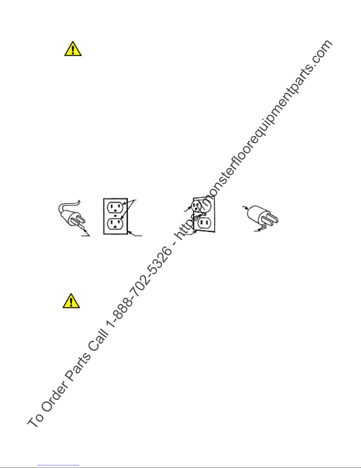
This appliance is for use on a nominal 120 volt circuit, and has a grounding plug that looks like the plug illustrated in Figure 1 below.
A temporary adapter illustrated in gures 2 and 3 may be used to connect this plug to a 2-pole receptacle as shown in gure 2, if a
proper outlet is not available. The temporary adapter should be used only until a properly grounded outlet (Figure 1) can be installed
by a qualied electrician . The green-colored rigid ear, tab, or the like extending from the adapter must be connected to a permanent
ground such as a properly grounded outlet box cover. Whenever the adapter is used, it must be held in place by a metal screw.
Grounding adapters are not approved for use in Canada.
Replace the plug if the grounding pin is damaged or broken.
The green (or green/yellow) wire in the cord is the grounding wire. When replacing a plug, this wire must be attached to the grounding
pin only.
Extension cords connected to this machine should be 12 gauge or larger, three wire cords, with three prong plugs and outlets. DO
NOT use extension cords more than 50 feet (15 m) long.
PLEASE NOTE: FOR NORTH AMERICA ONLY (EXCEPT CANADA)
TENGA EN CUENTA: SOLO PARA AMERICA DEL NORTE (EXCEPTO EN CANADÁ)
Grounded Outlet
Grounding Pin
(Clavijade conexión a tierra)
INSTRUCCION DE CONEXION
Figure 1
(Figura 1)
(Toma de corriente)
Adapter
(Adaptador)
Metal Screw
(Tornillo de metal)
Grounded Outlet Box
(Caja de la toma de
corriente)
Figure 2
(Figura 2)
Adapter
(Adaptador)
Tab For Grounding Screw
Ficha para el Torniilo de tierra
Figure 3
(Figura 3)
Este aparato debe de tener conexión a tierra, si sucediera una falla eléctrica la conexión a tierra proporciona un camino de menor
resistencia para la corriente eléctrica para reducir el riesgo de un choque eléctrico. Este aparato esta equipado de acuerdo con todos los
códigos y ordenanzas locales.
PELIGRO!!!
La conexión inadecuada del conductor de tierra del equipo puede resultar en un riesgo de choque electrico. Consulte con un electri-
cista calicado o personal del servicio si tiene alguna duda en cuanto a la conexión. No modique el enchufe previsto con el aparato.
Si no encaja en la toma de corriente debera de instalar la toma adecuada por un electricista calificado.
Este aparto es para su uso en un circuito de conexión a tierra que se parece al ilustrado en la gura 1 mas abajo. Un adaptador temporal se ilustra en las guras 2 y 3 podrán ser utilizados para conectar el enchufe a un tomacorriente de 2 polos como se muestra en
la gura 2 si una toma de corriente adecudad no está disponible. El adaptador temporal debe utilizarse solamente hasta que una toma
de tierra (gura 1) pueda ser instalada por un electricista calicado. El verde de la oreja rigida de color, en la cha o similares, que se
extiende desde el adaptador debe de estar conectado a una toma de tierra permanente como una caja eléctrica debidamente conectada a
tierra. Dondequiera que el adaptador se utiliza, debe ser mantenido en su lugar por un tornillo metálico. Los adaptadores de conexión a
tierra no estan aprobados para so uso en Canadá.
Vuelva a colocar el enchufe si la patilla de tierra está roto o dañada.
El alambre verde (o verde/amarillo) en el cable es el alambre de conexión a tierra. Al sustituir un enchufe este cable debe estar
conectado a la clavija de conexión a tierra solamente.
Los cables de extensión conectados a esta máquina deben de ser de 12 o mayor calibre, tres cables de alambre, con enchufes de tres
puntas y puntos de venta. No utilize cables de extensión de mas de 50 pies (15 metros) de largo.
4
Page 6
E-Glide 17” and 20” Electro Roto Section III
To Order Parts Call 1-888-702-5326 - https://monsterfloorequipmentparts.com
Owner’s Manual Operating Instructions
OPERATING INSTRUCTIONS
A. PREPARATION AND SET-UP
1. Roto
a. Check the roto and components to insure that they are in good operating
condition.
2. Quick Release Handle
a. The handle of your machine can be adjusted to any comfortable work position.
Simply lift the handle-locking device located on the lower handle shaft to release
the lock. Then adjust the handle to the desired position and push down rmly
with hand or rmly with foot pressure to lock the handle in place.
b. Adjust the handle to a position where you can control the machine and where the
disc surface balances at and level on the oor. Typically, the upper handle cross
bar should be adjusted to a height 1” under the bottom of the back trouser pocket.
Do not operate until Handle Quick Release is properly adjusted.
3. Driving Assemblies
a. With the power disconnected and the machine tipped back on the oor, attach
the disc driving assembly to the drive cover of the gearbox by lining up the three
notches in the driving assembly with the three lugs on the drive cover. Insert the driving
assembly and twist the assembly counterclockwise until it locks in place. The disc may
be mounted before or after attaching the drive assembly.
b. Always remove the drive block prior to transporting machine to the next station.
Place block on the cord hook.
WARNING!!
NEVER “jump start” the roto by holding the roto over the driving assembly to attach while the motor is
running. This is a sure way to ruin the motor, break the coupling between the motor and the gearbox, or
wear the adapter plate of the driving assembly. Evidence of this will void the warranty.
c. Remember, none of the driving assemblies should be used directly on the oor
without a maintenance disc or carpet bonnet.
5
Page 7
E-Glide 17” and 20” Electro Roto Section III
To Order Parts Call 1-888-702-5326 - https://monsterfloorequipmentparts.com
Owner’s Manual Operating Instructions
4. Solution Tank
a. Be sure the lter is securely seated into the bottom opening inside the tank.
b. To ll, set the shutoff valve in the closed position and the roto handle in a stand-up
position, slightly offset so accidental spillage will not drop on the motor.
c. Check the electro valve to ensure it is working properly, then open the shut-off valve
(test the electro valve before the driving assembly is mounted)
B. GUIDELINES FOR OPERATION
1. On-Off and Safety Switch Lock
a. Plug your machine into the correct electrical wall outlet, with the machine tipped back.
b. A safety lock-out switch has been provided to prevent accidental start-up of your
machine. Press this lockout switch, (located on top of the switch box, between the
handle grips) forward to release the operating lever. The lockout switch will spring back
into the safety lock position when you release the switch lever.
c. With the safety switch in the forward position, pull up on either the right or left hand
trigger switch located under the handle grips to operate the machine. To stop the
machine, simply release the trigger, allowing the safety switch to re-engage.
2. Solution Feed
a. To activate the Electro Valve to feed solution, pull up on both switch levers
simultaneously. The valve remains on until one side is released.
3. General Guidelines
a. Your roto is a very sensitive and powerful unit. When in operation, it should be guided
gradually and smoothly without sudden or rough motions. Practice with the machine on
a smooth surface, in a remote untravelled location, rst until you have experience
in operating the unit.
b. To move your machine to the right, slowly apply SLIGHT UPWARD pressure on the
handle with both hands.
c. To move the machine to the left, slowly apply SLIGHT DOWNWARD pressure on the
handle again with both hands.
d. To move the machine directly forward, torque the handle SLIGHTLY DOWNWARD on
the LEFT side.
e. To move the machine to the rear, torque the handle SLIGHTLY DOWNWARD on the
RIGHT side.
f. Your machine will operate differently on various surfaces. For example, there will be
much more resistance when the machine is used with a shampoo disc on a carpeted
surface than with a polishing disc on a smooth surface.
g. If there is an incidence of fuse blowing, the roto should be used on a 20 amp circuit
wherever possible.
6
Page 8
E-Glide 17” and 20” Electro Roto Section III
To Order Parts Call 1-888-702-5326 - https://monsterfloorequipmentparts.com
Owner’s Manual Operating Instructions
C. POST OPERATION
1. Driving Assemblies
a. Remove the electrical plug from the wall outlet.
b. Put the handle into the upright position. Tilt the machine back so the handle is at on the
oor and driving assembly is perpendicular to the oor.
c. Hold the driving assembly in both hands and turn it clockwise in a jerking motion. (A
screwdriver may be inserted between the drive lug and clutch plate to assist in the release
of a jammed driving assembly.)
d. Always remove the driving assembly before standing the machine upright for storage.
There is a vertical lug on the cord winder bracket for hanging the driving assembly.
2. Solution Tank (Gravity Feed)
a. To empty the tank, close the tank shutoff valve, remove the bottom end of the solution
hose from the hose barb on the Electro Valve.
b. Hold the disconnected end of the solution hose in a bucket or other container. Open the
shutoff valve and let the solution drain from the tank.
c. Check the lter in the tank to ensure it is not clogged.
3. Clean Up
a. Always wipe the machine down with a clean, soft, damp cloth before storing it.
4. Power Cord Storage
a. When not in use, loosely wind the power cord around the cord storage hooks on the
handle shaft and one of the handle grips. Winding the cord double in a gure “8” pattern
will save winding and unwinding time and prevent kinks in the stretched-out cord.
5. Storage
a. Always store your machine in a clean, dry location with the handle in an upright position
and with driving assembly removed. Never lay the machine down to store.
7
Page 9
E-Glide 17” and 20” Electro Roto SECTION IV
To Order Parts Call 1-888-702-5326 - https://monsterfloorequipmentparts.com
Owner’s Manual PREVENTIVE MAINTENANCE GUIDE
This preventive maintenance guide will be helpful in keeping your roto in top operating condition to
help ensure maximum usage and life.
The time intervals shown (daily, weekly, monthly or quarterly), are based on a typical 8 hour day.
Daily Checks
1. Check the lter inside the bottom of the tank. Clean or replace as required.
2. Clean the base of the roto.
3. Check electrical cords and plugs for loose prongs and connections, cracks or wear on
insulation
Monthly Checks
CAUTION: Do not attempt any repairs without rst disconnecting the electrical cords from the power
source.
1. Check the toggle adjustment lever action, holding the handle position securely and
releasing properly. Adjust the hex nut, if required.
2. Test the tightness of the two handle cover screws at the back of the handle crossbar and
tighten as required.
3. Clean any chemical deposits from all external surfaces around the motor, tank,
electro- valve, etc.
4. Clean the motor head.
5. Check the tank and ttings for leaks.
Quarterly Checks
CAUTION: Do not attempt any repairs without rst disconnecting the electrical cords from the power
source.
1. Clean the cooling air passage on the top and bottom of the motor.
2. Check the bumpers round the base of the machine. Clean and replace, if worn, or if they
no longer t properly.
3. Check the tightness of the fasteners in the lower brackets holding the handle to the base,
screws in the upper and lower cord hooks, screws holding the motor to the base.
4. Disassemble the electro valve; clean and check the seat at the bottom of the plunger.
5. Check the disc driving assembly for loose fasteners or damage repair if needed.
8
Page 10

E-Glide 17” and 20” Electro Roto Section V
To Order Parts Call 1-888-702-5326 - https://monsterfloorequipmentparts.com
Owner’s Manual TROUBLESHOOTING GUIDE
This troubleshooting guide will assist in locating a malfunction that may develop.
To identify parts described here, refer to the pictures and the parts lists in the back of this manual.
For a detailed description of how to repair or replace parts, see the Roto Repair Guide.
TABLE OF CONTENTS
A. “Dead” Motor and Electro Valve Not Working
B. No Solution Flow Through Electro Valve
C. Solution Leak Through Electro Valve Power Off
D. Frequent Fuse Blowing During Operation
E. Drive Assemblies or Brushes Lock onto Roto, Difcult to Remove
F. Roto Wobbles
G. Handle Adjustment (Quick Release) Working Improperly
H. Noises in Roto
I. Electrical Leakage
J. Defects in Motor Gear Unit
K. Overheating of Motor
A. “DEAD” ROTO MOTOR AND ELECTRO VALVE NOT WORKING
1. Not securely plugged into wall outlet. Twist lock not secure
2. Fuse or circuit breaker blown.
3. Defective plug; wire broken or loose on electrical cord.
4. Broken or loose connection in twist lock connectors at the roto handle.
5. Defective electric cord.
6. Defective main switch.
7. Switch lever.
8. Defective motor (electro valve may still work)
B. NO SOLUTION FLOW THORUGH ELECTRO VALVE
1. Manual shutoff valve under the tank is closed.
2. Clogged lter inside the bottom of the tank.
3. Electro valve is not working (no click).
i. Foreign matter in the valve is preventing movement
(may hum but not operate).
ii. Defective valve switch on the handle.
iii. Valve switch linkage not engaged.
iv. Electro Valve coil is open (burned out), or the connection is loose inside
the coil housing.
C. SOLUTION LEAK THROUGH ELECTRO VALVE (NO POWER ON)
1. Foreign matter inside valve is holding the valve open; i.e., lint, fuzz, etc.
(especially if the lter inside the tank is missing).
2. Dried oor nish inside the valve prevent the plunger from sealing.
9
Page 11

E-Glide 17” and 20” Electro Roto Section V
To Order Parts Call 1-888-702-5326 - https://monsterfloorequipmentparts.com
Owner’s Manual Troubleshooting Guide
3. A swollen or disintegrated seal at the base of the plunger, especially if high
concentrations of solvents are used, such as GSL, DiasasterClene, MBI, in
cleaning or shampoo mixtures.
D. FREQUENT POWER OVERLOADS – BLOWN BREAKERS OR FUSES
(Disconnect from the power source before making checks.)
1. Spray bufng disc is excessively clogged or glazed.
2. Shampoo disc too dry.
3. Line voltage too low, less than 110 volts.
4. Defect in motor (see “K”).
5. Start-Stop repeated too often in a short interval.
E. DRIVE ASSEMBLIES OR BRUSHES CONSISTENTLY JAM ON HUB.
DIFFICULT TO REMOVE.
(Disconnect from the power source before making checks.)
1. Worn clutch plate on drive block or brush.
2. Worn lugs on hub at base of motor gear unit.
NOTE: “Stubborn” driving assemblies and brushes can be removed by inserting a
large screwdriver through the center hole in the driver or brush prying the clutch
surfaces apart.
F. ROTO WOBBLES
(Disconnect from the power source before making checks.)
1. Disc not centered under drive assembly.
2. Shampoo disc matted on one side.
3. Disc or brush bristles worn unevenly or attened from improper storage.
4. Loose or sheared screw clutch plate to drive assembly or brush back.
5. Warped backing, especially wood-backed assemblies.
G. HANDLE HEIGHT ADJUSTMENT (QUICK RELEASE) WORKING IMPROPERLY
1. Handle skips or won’t lock. Tighten ex lock hex nut on quick release assembly.
2. Does not release handle – loosen ex lock hex nut.
3. Handle tube has buildup of soil or rust.
NOTE: If above adjustments cannot be achieved, cam surfaces on quick release handles
or on the washer may be worn. Replace quick release handle and washer.
10
Page 12

E-Glide 17” and 20” Electro Roto Section V
To Order Parts Call 1-888-702-5326 - https://monsterfloorequipmentparts.com
Owner’s Manual Troubleshooting Guide
H. NOISES IN ROTO
(Disconnect from power source before making checks.)
1. Motor gearbox rubbing base (motor slightly shifted on mounting holes).
Loosen motor mounting screws and shift away from the rubbing area.
2. Driving assembly or brush back rubs against housing.
3. Clutch plate loose or cracked.
4. Clicking noise – feed tube bent out of position.
5. Noises in the motor gear unit – see “J”.
I. ELECTRICAL LEAKAGE (Mild feeling of electricity when touching metal parts)
(Disconnect from power source before making checks.)
1. Reversed polarity of the plug in the receptacle. No ground.
2. Worn insulation in the shunt cord, especially where it passes through the strain
reliever.
3. Defective, cracked or worn insulation in other wiring, especially if moisture has
been present for an extended time.
4. Leakage in the small Electro Valve switch.
5. Leakage in the motor (unplug at the base of the roto and check if the leakage
disappears).
6. Leakage around the main switch; wire rubbing inside of the housing, etc.
7. Wet connections in the electrical components.
J. DEFECTS IN MOTOR GEAR UNIT
(Disconnect from power source before making checks.)
1. Fuse or circuit breaker blows repeatedly after factors in “D” above have been
cleaned.
a. Stationary switch or centrifugal switch worn.
b. Bearings, other parts worn, causing long time lag before starting switch
trips.
2. Motor runs, but gearbox does not turn. Check for broken coupling.
3. Excessive sparks inside the motor when started – dirty contacts on stationary
switch. some ash is to be expected when the centrifugal switch operates.
4. Motor overheats.
a. Dirt, lint, fuzz, etc., blocking cooling air inlets at the top of the motor
(beneath chrome cover) or air outlets.
b. Low line voltage
c. Overworked on rough high friction surface
11
Page 13

E-Glide 17” and 20” Electro Roto Section V
To Order Parts Call 1-888-702-5326 - https://monsterfloorequipmentparts.com
Owner’s Manual Troubleshooting Guide
5. Grease Leak – leaking gasket or seals in gearbox.
6. Noises in motor gear unit.
a. Loading spring (nger washer) at top motor bearing out of proper
position.
b. Centrifugal or stationary switch shifted
c. Worn coupling (excessive play of hub)
d. Loose screws.
e. Worn gears, bearings, and other parts.
K. OVERHEATING OF MOTOR
The Roto has been operated for long periods of time on low voltages, which causes excessively
high operation temperatures which, in turn, may result in damage to the insulation on the wind
ing. Low voltage may result from using an extension cord of lesser wire size than #12.
It is recommended to obtain a #12 three-wire extension cord if it is necessary to use more than
one 50 foot cord.
NOTE: The 17” and 20” machine (1-1/2 HP) motor plate states a 40 degree C (centigrade)
heat rise. This means a rise of 104 degrees F (Fahrenheit). Add to this 70 degrees F
for room temperature, and you will nd that the motor will seem very hot (174 degrees F).
This is not cause for alarm.
NOTE: Motors can normally run too hot to touch. An overheated motor may give off an oder, run slow,
start slow, blow fuses, and get hot enough to boil water on its surface.
E-Glide 17” and 20” Electro Roto Section VI
Owner’s Manual REPAIR GUIDE
REPAIR GUIDE
This repair guide is written to help make repairs or replace parts.
Simpler repairs where all parts are visible are not listed here’ i.e., replacing a hand grip or
a wheel. This guide is written for those repairs that contain “hidden” parts, or require a
specic technique.
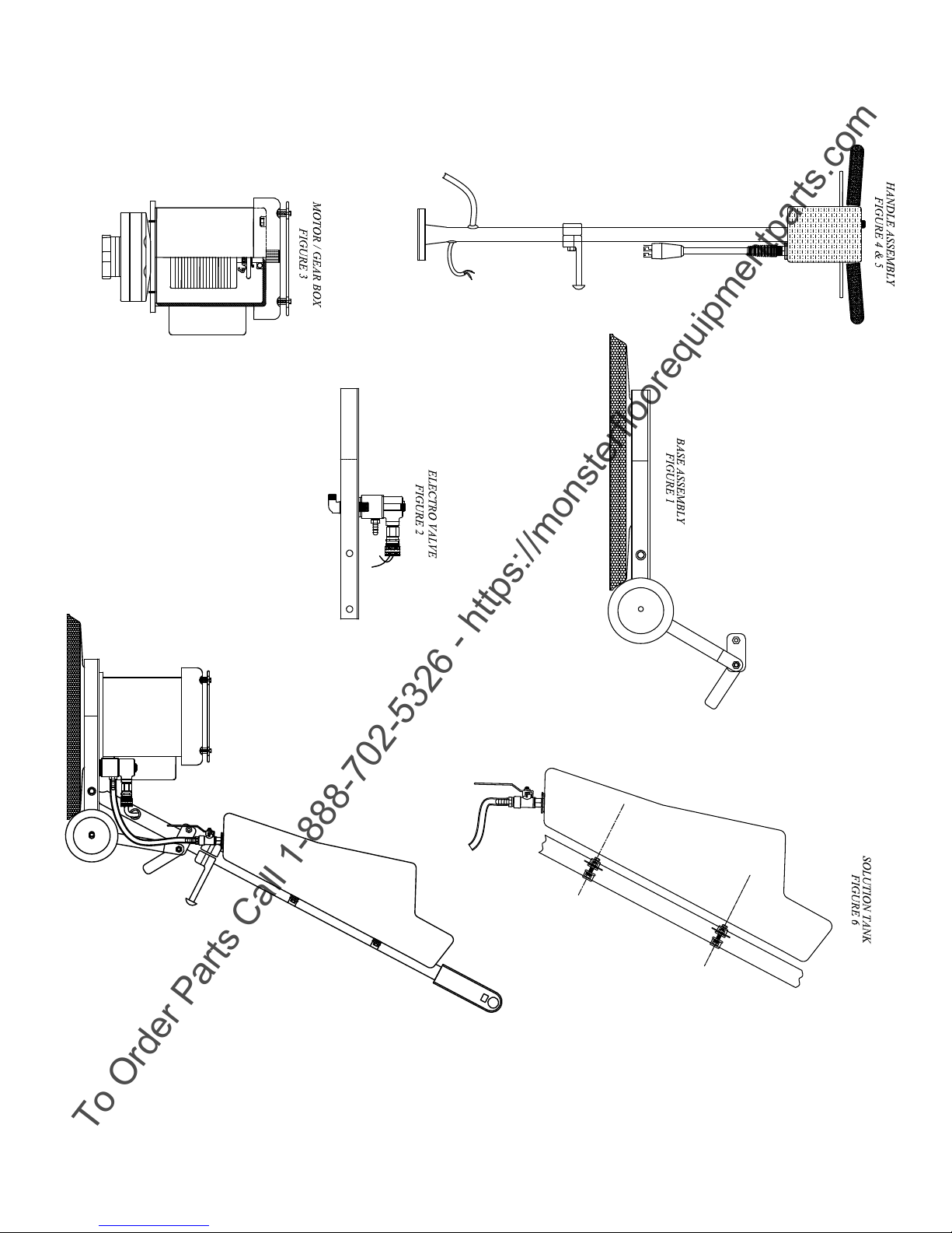
Use the illustrations as reference. Refer to the corresponding gure for parts in the
pictures of the roto parts.
12
Page 14

E-Glide 17” and 20” Electro Roto Section VI
To Order Parts Call 1-888-702-5326 - https://monsterfloorequipmentparts.com
Owner’s Manual Repair Manual
TABLE OF CONTENTS
A. Main Switch and Electro Valve Switch
B. Shunt Cord or Strain Reliever
C. Electro Valve
D. Bumper
E. Motor Gear Unit
F. Remove and Replace Handle Assembly (for Base Assembly)
A. MAIN SWITCH OR ELECTRO VALVE SWITCH, REPLACE
(Disconnect from power source before making repairs.) (Refer to parts illustration of
Handle Assembly.)
1. Remove the switch cover by removing two screws and lifting cover straight up.
2. The Roto main switch and Electro Valve switch are now exposed and can be
replaced.
NOTE: To avoid incorrectly connecting the wires on the new switch, hold the
old and new switch side by side before disconnecting any wires. Disconnect
one wire from the old switch, move it to the same terminal on the new switch,
and connect it securely. Move the second wire from the old switch to the new
switch, and so on.
3. Reverse the above procedure to re-assemble.
NOTE: The tab extension on the front side of the cover ts inside the top of the handle
tube. Take care not to damage the wire insulation when reassembling the cover.
B. SHUNT CORD OR STRAIN RELIEF, REPLACE
(Disconnect from power source before making repairs.)
(Refer to parts illustration of Roto Handle Assembly. Figures 4 & 5)
1. Remove the switch cover, as described in “A”.
2. Disconnect the wires from the shunt cord, noting their color and position on
the switch.
NOTE: The ground wire is connected to the grounding screw.
3. Loosen the conduit nut and unscrew the strain reliever assembly from the switch
housing. You will have to pry the gripper teeth up to free the cord.
4. Reverse the procedure to assemble.
13
Page 15

E-Glide 17” and 20” Electro Roto Section VI
To Order Parts Call 1-888-702-5326 - https://monsterfloorequipmentparts.com
Owner’s Manual Repair Guide
C. ELECTRO VALVE, DISASSEMBLY PROCEDURE(Figures 2 & 5)
(Disconnect from power source before making repairs.)
(Refer to parts illustration of Electro Valve Assembly.)
1. Remove the nut on top of the Electro Valve and lift off the housing and coil together.
2. Unscrew and remove the sleeve assembly. The internal parts can now be
lifted out. The seal slips off the end of the plunger for cleaning or replacement. Do not
allow springs or washers to drop and become lost.
3. Inspect the valve seat for debris or scores which may call for a valve body replacement.
4. When reassembling, insure that the coil lead wires t up inside the housing and are not
pinched between the housing and body.
D. BUMPER, REPLACE
(Disconnect from power source before making repairs.)
(Refer to parts illustration of Roto Base Assembly.)
1. Remove original bumper by rolling it off the brush cover.
2. Install the new bumper in reverse manner on to the brush cover.
3. Attach the driving assembly or brush to the Roto and check to ensure that the
block or brush clears.
E. MOTOR GEAR UNIT, REPLACE
(Disconnect from power source before making repairs.)
(Refer to parts illustration of Motor Parts. Figure 3)
1. Remove switch housing and disconnect the motor cord from switch (black
wire), ground (green wire), and wire nut (white wire). Unfasten the upper
strain relief and pull the cord until it is free from the lower end of the handle.
2. Lay the roto upside down on the oor or bench, base up.
3. Remove the 4 screws and washers that mount the motor to the base of the roto.
4. Lift the roto off the base of the motor.
5. Reverse the above steps to replace the motor. Push the cord through the
grommet from the lower end of the handle. Lubricate the cord if necessary.
NOTE: Repairs of the motor gear unit itself are usually not recommended unless the
mechanic has had experience with these motors and gear cases.
We recommend referring the repair to a local service center or contact your distributor for the
latest repair procedures. For those who wish to repair motor gear units themselves, the
illustrations in the Product Guide show the order of assembly quite clearly. On gearboxes, be
certain to use the lubricants and sealers specied in the places spelled out in the parts list.
F. HANDLE ASSEMBLY REPLACEMENT
Remove push nut, cotter pin, and washers. Disconnect in-handle cord from the switch and
power cord. Remove the loop clamp holding the cord. Slide the handle shaft through handle
and remove. Install new handle, rewire and test the machine.
14
Page 16
To Order Parts Call 1-888-702-5326 - https://monsterfloorequipmentparts.com
15
Page 17
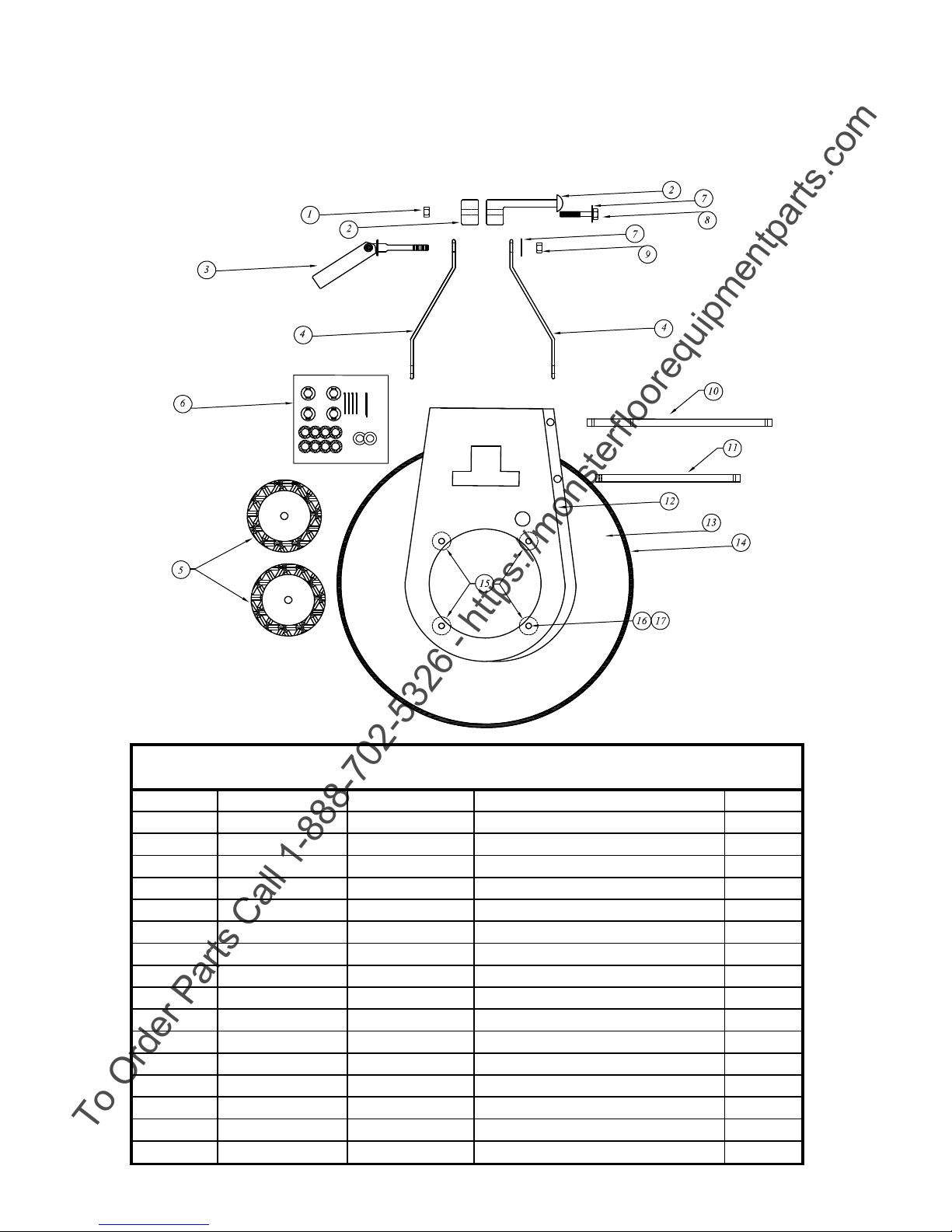
Figure 1
To Order Parts Call 1-888-702-5326 - https://monsterfloorequipmentparts.com
17 & 20 INCH BASE ASSEMBLY
ARAMARK 17 & 20 INCH BASE ASSEMBLY
Illus. Qty.
No: 16 inch 20 inch Description Req'd.
1 H0057AR H0057AR NUT 3/8-16 THIN NYLOCK 1
2 HP0004-BLACKAR HP0004-BLACKAR CORD HOOK BODY & CAP 1
3 HP0003-BLACKAR HP0003-BLACKAR CAM LOCK ASSEMBLY 1
4 S0018PAR S0018PAR CONNECTING LEG BLK 2
5 C0004BBAR C0004BBAR WHEEL 5 INCH BALL BEARING 2
6 HP0001AR HP0001AR HARDWARE PACK WHEEL 1
7 H0016AR H0016AR WASHER FLAT 3/8 BLK 2
8 H0044AR H0044AR BOLT 3/8-16 X 2 1/2 GR 8 1
9 H0015AR H0015AR NUT 3/8-16 HEX NYLOCK 1
10 M0005PAR M0005PAR AXLE WHEEL 1
11 M0006PAR M0006PAR SHAFT HANDLE 1
12 W0001-1PAR W0001-1PAR FRAME 1
13 S0003CPAR S0004-1CP BRUSH COVER CHROME PLATED 1
14 C0001 C0002 BUMPER 1
15 M0004AR M0004AR SPACER 4
16 H0011AR H0011AR BOLT 5/16-18 X 2 SOCKET CAP BLK 4
17 H0010AR H0010AR LOCK WASHER 4
16
Page 18
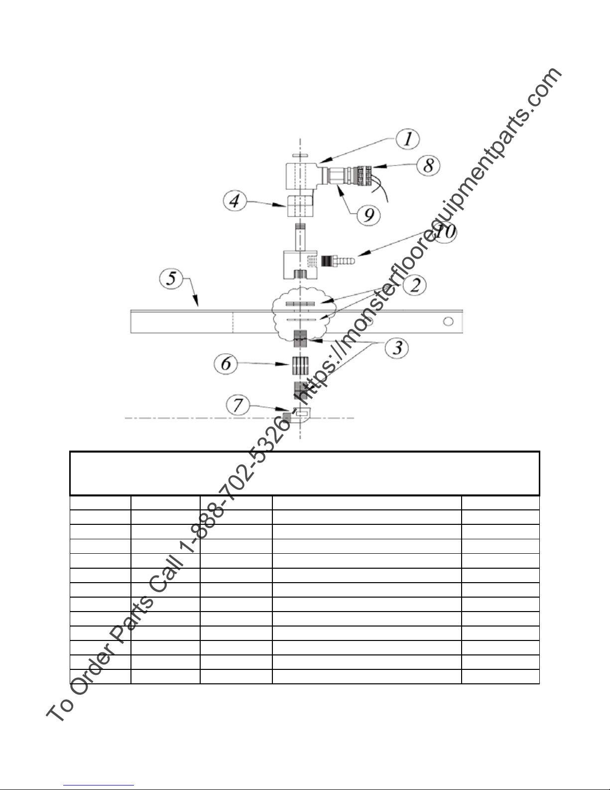
ARAMARK ELECTRO VALVE ASSEMBLY
No: 16 inch 20 inch Description Req'd.
2,3,6,7,10 AR0036-KIT AR0036-KIT ELECTRO VALVE HARDWARE KIT 1
2 AR50261 AR50261 WASHER SS 1.5 OD 3
4 AR50280 AR50280 COIL REPLACEMENT 115 VOLT 1
5 ARW0001-1P ARW0001-1P FRAME SHOWN FOR ASSY REF. 1
7 AR50291 AR50291 3/8 INCH COMPRESSION FITTING 1
9 AR50208-1P AR50208-1P EXT. BUSHING 1
Figure 2
To Order Parts Call 1-888-702-5326 - https://monsterfloorequipmentparts.com
Illus. Qty.
1,8,9 AR50209-KIT AR50209-KIT ELECTRO VALVE KIT COMP 1
1 AR50209 AR50209 ELECTRO VALVE 1
3 ARH0120 ARH0120 NIPPLE 3/8 X 1 SS 2
4 AR50209-2 AR50209-2 COIL REPLACEMENT 230 VOLT 1
6 ARH0118 ARH0118 3/8 PIPE COUPLING-FULL HEX 1
8 AR50208 AR50208 STRAIN RELIEF WATER TITE 1
10 AR50263P AR50263P BARB FITTING 3/8 INCH 1
17
Page 19
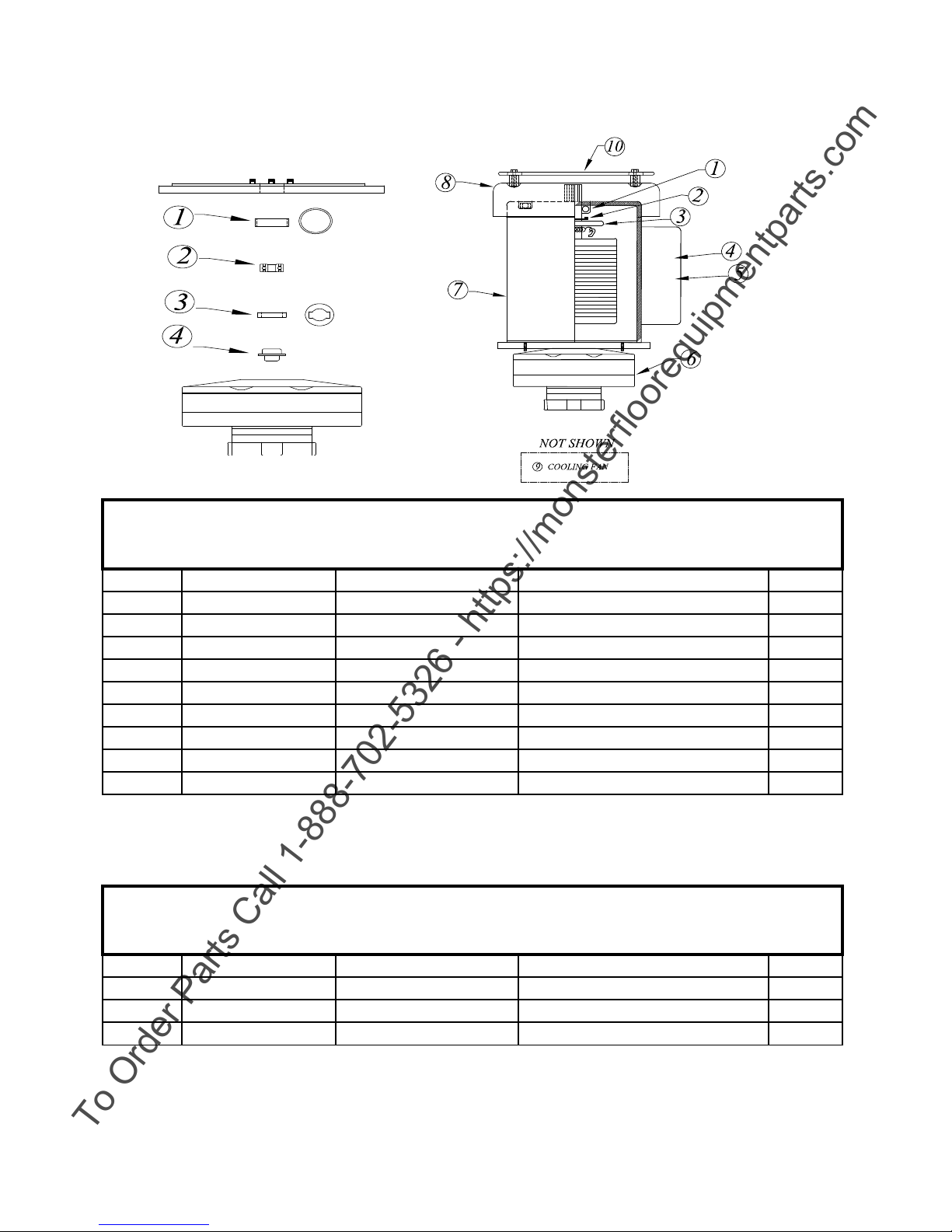
Figure 3
5 ARE0030-180R ARE0030-180R RUN CAPACITOR 1
No: 16 inch 20 inch Descripon Req'd.
To Order Parts Call 1-888-702-5326 - https://monsterfloorequipmentparts.com
ARG0002XHD-180F ARE0030HDMG MOTOR AND GEAR BOX ASSY.
GEAR BOX COMP.
Illus. Qty.
No: 16 inch 20 inch Descripon Req'd.
1 ARE0030-180B ARE0030-180B TOP MOTOR BEARING 1
2 ARE0030-180SS ARE0030-180SS STATIONARY SWITCH 1
3 ARE0030-180CS ARE0030-180CS CENTRIFUGAL SWITCH 1
4 ARE0030-180S ARE0030-180S START CAPACITOR 1
6 ARG0002XHD-180F ARG0002XHD-180F GEAR BOX COMP. 1
7 ARE0030HDM ARE0030HDM (MOTOR ONLY)1.5 HP LEESON 1
8 ARE0030-180MC ARE0030-180MC MOTOR COVER CHROME 1
9 ARE0030HDMCF ARE0030HDMCF FAN COOLING 1
10 ARS0049-KIT ARS0049-KIT MOTOR COVER FAN GUARD KIT 1
Illus. GEAR BOX REPLACEMENT PARTS Qty.
1 ARG0001SS ARG0001SS SPACER SLEEVE 1
2 ARG0001B ARG0001B BEARING 1
3 ARG0001RW ARG0001RW RETAINING WASHER THICK 1
4 ARG0001C-1 ARG0001C-1 COUPLER STEEL 1
18
Page 20
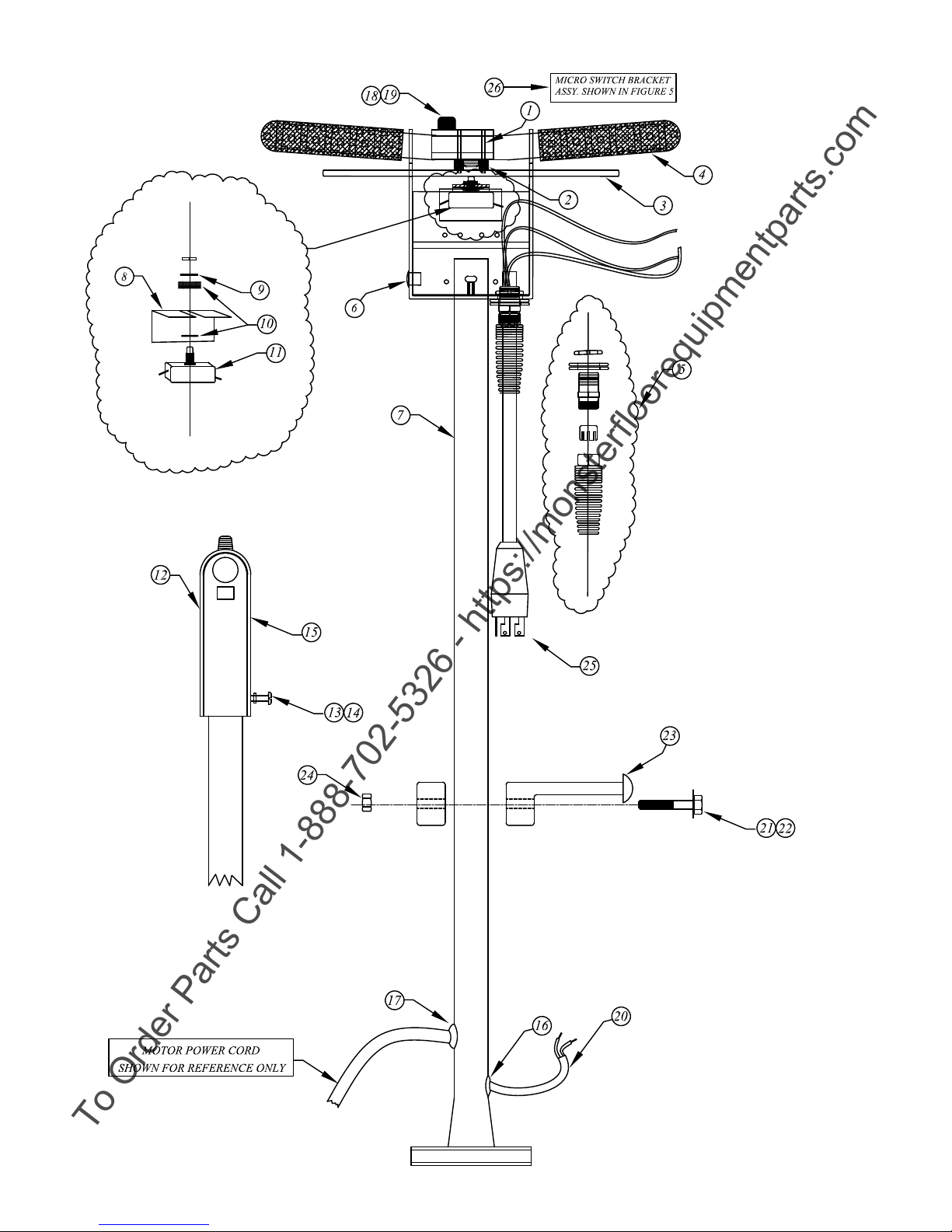
Figure 4
To Order Parts Call 1-888-702-5326 - https://monsterfloorequipmentparts.com
19
Page 21
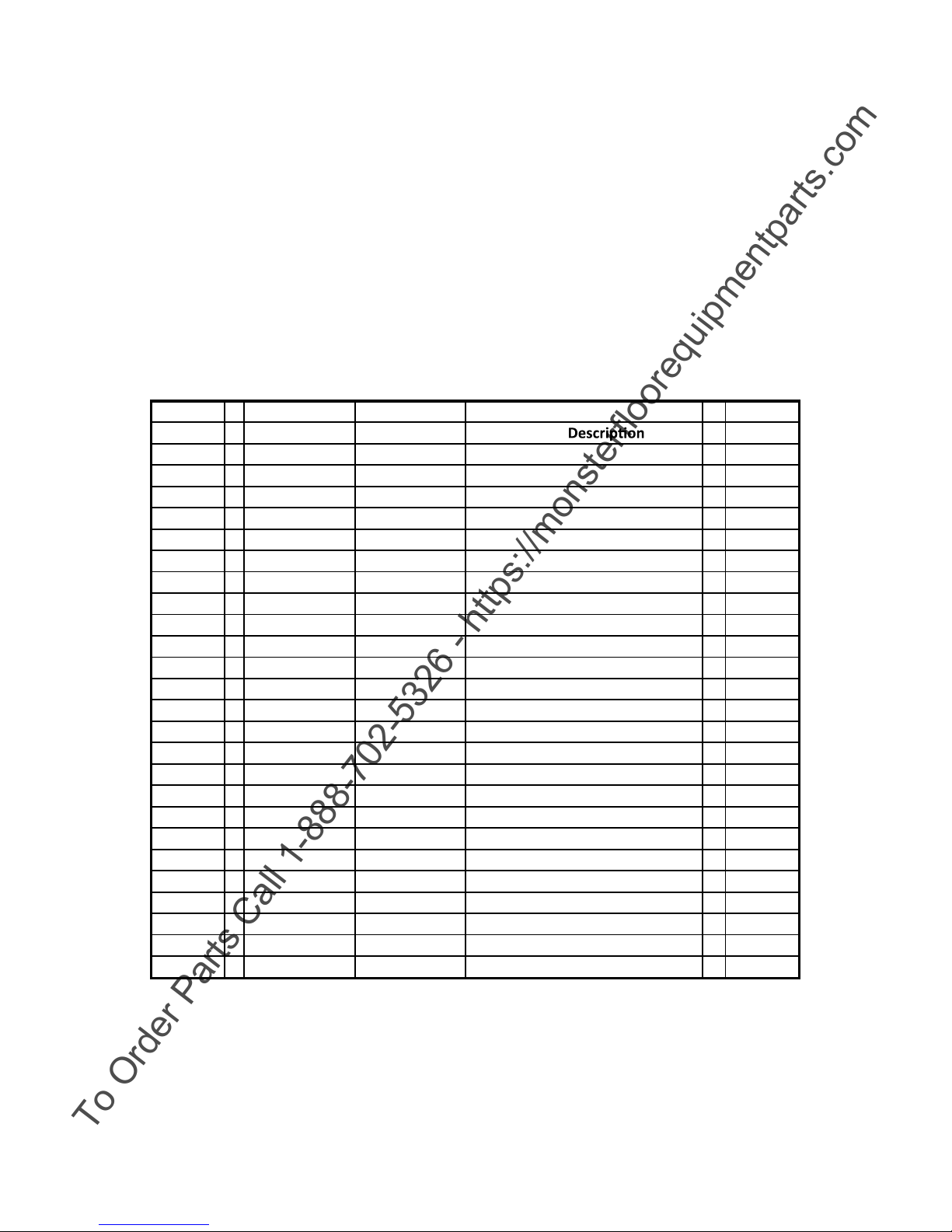
HANDLE ASSEMBLY COMPLETE AR50764
To Order Parts Call 1-888-702-5326 - https://monsterfloorequipmentparts.com
Illus. Qty.
No: 16 inch 20 inch
1
2
3
4
5
6
7
8
9
10
11
12
13
14
15
16
17
18
19
20
21
22
23
24
25
ARH0012 ARH0012 ROLL PIN 2
ARH0023 ARH0023 SPRING 2
ARS0008-1P ARS0008-1P TRIGGER BLK. 1
ARC0007 ARC0007 GRIP HANDLE BLK. 2
ARH0021 ARH0021 STRAIN RELIEF 1
ARH0055 ARH0055 BUTTON PLUG 1
AR50953 -1P AR50953 -1P HANDLE CHROME PLATED 1
ARH0013 ARH0013 INSULATION SWITCH 1
ARH0061 H0061AR WASHER LOCKING INT. 1
ARH0008-1 ARH0008-1 WASHER FLAT (AS REQ'D) AR
E0007 E0007 SWITCH MAIN ON / OFF 1
ARW0003-1P ARW0003-1P SWITCH BOX COVER CHROME 1
ARH0002 ARH0002 SCREW 10-24 X 1 2
ARH0020 ARH0020 WASHER LOCKING INT. 2
ARL0005-1 ARL0005-1 LABEL SAFETY 1
AR50771 AR50771 GROMMET CORD ELECTRO VALVE 1
AR50724 GROMMET MOTOR CORD 1
ARC0003-1 ARC0003-1 SAFETY SWITCH 1
ARH0014 ARH0014 SPRING SAFETY SWITCH 1
AR50765 CORD ELECTRO VALVE 1
ARH0044 ARH0044 BOLT 3/8-16 X 2-1/2 GR8 2
ARH0016 ARH0016 WASHER FLAT 3/8 2
ARHP0004-BLK ARHP0004-BLK BODY AND CAP BLK 1
ARH0024 ARH0024 NUT 3/8-16 BLK 2
AR50727 AR50727 POWER CORD PIG TAIL 1
AR50724
AR50765
Req'd.
20
Page 22
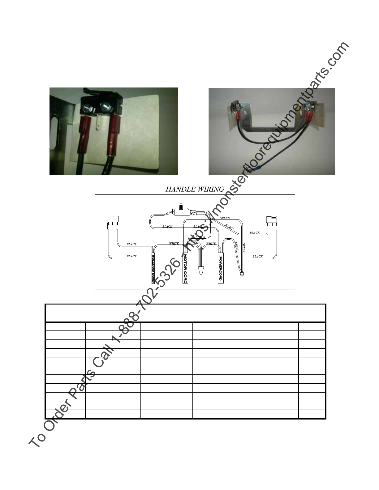
MICRO SWITCH BRACKET ASSEMBLY COMPLETE AR50964-KIT.
22
2
23
2
Figure 5
To Order Parts Call 1-888-702-5326 - https://monsterfloorequipmentparts.com
MICRO SWITCH BKT. ASSY COMPLETE AR50964-KIT
Illus. Qty.
No: 16 inch 20 inch Description Req'd.
13-23 AR50964-KIT AR50964-KIT MICRO SWITCH BKT. ASSY. COMP. 1
14
15
16
17
18
19
20
21
MICRO SWITCH BKT. 1
MICRO SWITCH 2
WIRE JUMPER MICRO SWITCHS 1
WIRE JUMPER MAIN SWITCH /MICRO 1
INSULATION MICRO SWITCH 2
NUT #2-56 HEX 4
WASHER LOCK #2 INTERNAL 4
SCREW #2-56 X 1/2 INCH 4
SCREW 10-24 X 1/2 INCH
WASHER LOCK #10
21
Page 23
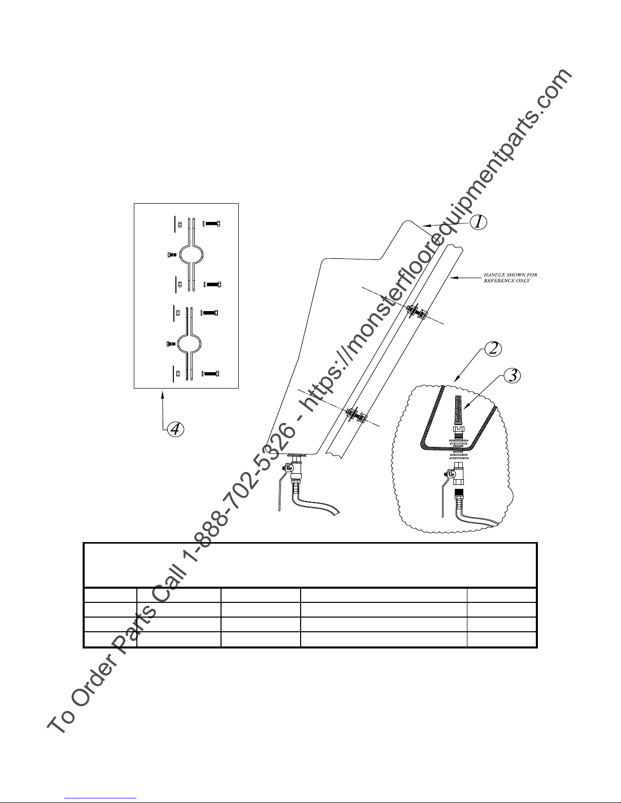
SOLUTION TANK ASSEMBLY
No:
16 inch 20 inch Description Req'd.
2 AR0033-KIT AR0033-KIT VALVE ASSEMBLY KIT 1
4 AR0035-KIT AR0035-KIT TANK MTG. HARDWARE KIT 1
Figure 6
To Order Parts Call 1-888-702-5326 - https://monsterfloorequipmentparts.com
Illus. Qty.
1 AR50794 AR50794 TANK ASSEMBLY COMPLETE 1
3 AR0034-KIT AR0034-KIT FILTER (6 PER PACK) 1
22
Page 24
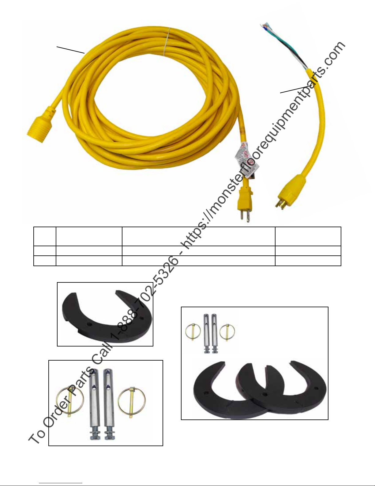
1
To Order Parts Call 1-888-702-5326 - https://monsterfloorequipmentparts.com
2
Illus.
No:
1 AR50698-1 Powercord Assembly 12-3 ST x 50 Ft., Yellow 1
2 AR50727 Pigtail 21” l Yellow 14-3 1
25 # Horse Shoe Weight
Stock
No.
AR0032-1P
Description
Optional Weight Post Kit
AR0032-KIT
No.
Reqd.
Weight Pin Kit
AR0032PIN
23
Page 25
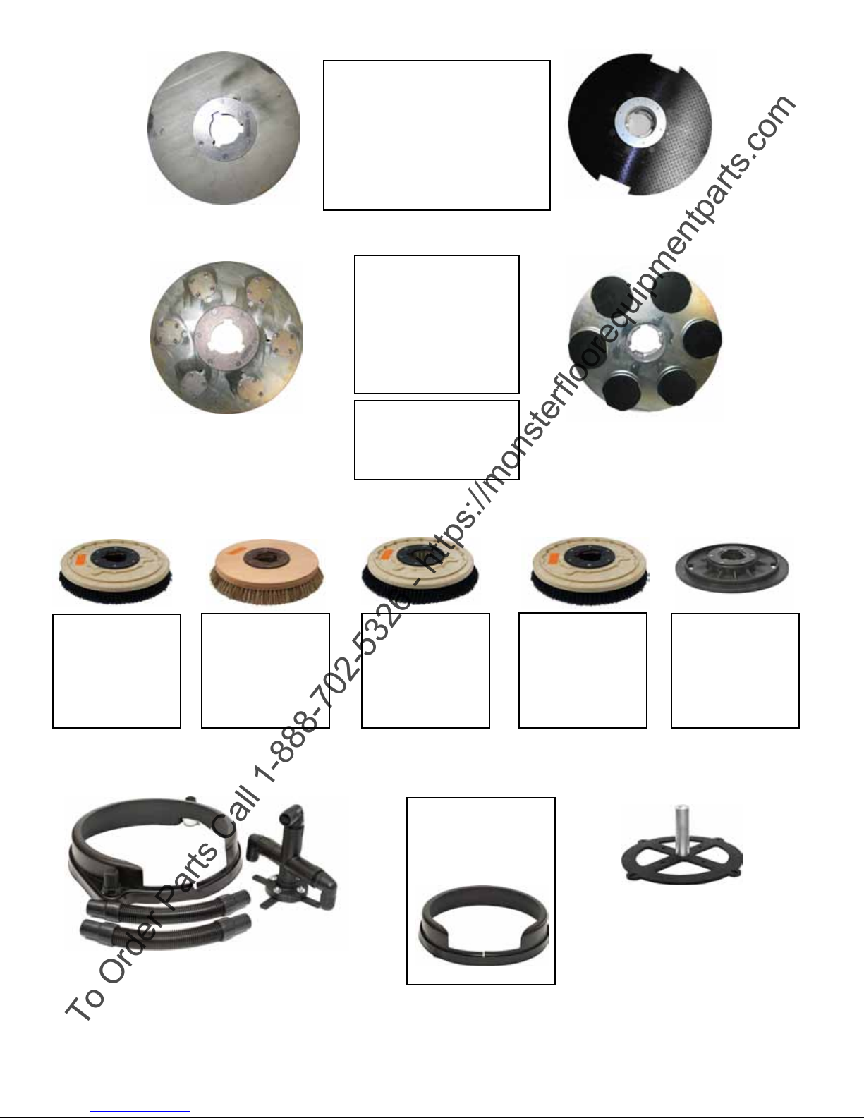
Weighted Diamond
To Order Parts Call 1-888-702-5326 - https://monsterfloorequipmentparts.com
Pad Driver:
13” A0017WTDPD (25#)
15” N/A
17” A0010WTDPD (46#)
20” A0011WTDPD (64#)
Poly Brush:
13” A0020
15” A0036
17” A0002
20” A0003
Top View
Top Veiw
Polish Brush:
13” A0021
15” A0035
17” A0004
20” A0005
Orbitec Diamond
Driver:
13” HP0018
15” N/A
17” HP0017
20” HP0020
Orbitec Diamond
Drivers have the
option of 3”, 4”, and
5” heads.
Nylon Brush:
13” A0016
15” A0037
17” A0006
20” A0007
Applix Face
6 Independently Ro-
tating Applix Faces
Grit (80) Brush:
13” A0018
15” A0038
17” A0008
20” A0009
Pad Driver:
13” A0017
15” A0034
17” A0010
20” A0011
Dust Pickup System For a
BRUTE Machine
Optional
splash guard
available in all
sizes.
HP0008-3INBRUTE
Motor Mounted Weight
Post Kit
24
Page 26
WARRANTY
To Order Parts Call 1-888-702-5326 - https://monsterfloorequipmentparts.com
E-Glide Electro Roto
WARRANTY
The Manufacturer warrants that this Electro Roto has been thoroughly inspected and tested, and found to be free
of defects in workmanship or materials, and guarantees to repair or replace free of charge (FOB Repair Center
Dock) any part or parts proven defective within one year from the date of purchase by the end-user. Ordinary
wear, accident, or misuse, are expressly excepted. Do not pick up hard or metallic objects which may damage unit and void warranty. This warranty does not cover normal wear parts such as cord, gaskets, switches,
bumpers, carbon brushes, bags, hoses, belts, etc. Warranty to include labor, in - bound and out-bound freight
charges.
EXCEPT AS TO TITLE AND MERCHANTABILITY, THIS WARRANTY IS IN LIEU OF ALL
OTHER WARRANTIES EXPRESSED OR IMPLIED. IN NO EVENT SHALL THE
MANUFACTURER BE LIABLE FOR CONSEQUENTIAL DAMAGES.
Hawk Enterprises of Elkhart, Inc.
52744 Park Six Court
Elkhart, IN 46514
Phone: (574) 294-1910
 Loading...