

hawa Concepta 40, Concepta 50, Concepta 25, Concepta 30 Planning And Installation Instructions

HAWA-Concepta 40/50
Planungs- und Montageanleitung
Beschlag für seitlich einschiebbare Mö belfronten aus Holz bis 40/ 50 kg.
Planification et instructions de montage
Ferrure pour façades de meubles en bois à escamotage latéral et pesant
jusqu'à 40/50 kg.
Planning and installation instructions
Hardware system for wooden pivot sliding cabinet fronts up to 40/50 kg.
Patente
Brevents
Patents
25738 -

1 Inhaltsverzeichnis
Inhalt
1 Inhaltsverzeichnis 2
2 Produktinformation 3
3 Sicherheitsvorschriften 3
4 Abkürzungen, Symbole 8
5 Übersichten 5.1 Übersicht: Anlage links 10
5.2 Übersicht: Connector 55 (optional) 11
5.3 Übersicht: Connector 110 mit und ohne Sockel (optional) 12
5.4 Übersicht: Zwei einliegende Dreh-Einschiebetüren 13
5.5 Übersicht: Positionsnummern 14
6 Planung 6.1 Planung: Türe einliegend 15
6.2 Planung: Führung für zwei einliegende Dreh-Einschiebetüren 16
6.3 Planung: Türe auf Boden und Oberboden aufschlagend mit Connector 55 17
6.4 Planung: Türe auf Boden und Oberboden aufschlagend mit Connector 110 18
6.5 Planung: Türe in Mauernische 19
Seite
7 Berechnung 7.1 Berechnung: Gewicht zu Türgrössenverhältnis 20
7.2 Berechnung: Masse Grundriss 21
7.3 Berechnung: Beschlagstiefe 23
7.4 Berechnung: Bohrpositionen 24
8 Vormontage 8.1 Vormontage: Bearbeitung Profile links 26
8.2 Vormontage: Bearbeitung Profile rechts 27
8.3 Vormontage: Türe 28
8.4 Vormontage: Korpusseite 29
8.5 Vormontage: Aussenseite 31
8.6 Vormontage: Anschlagdämpfung 32
8.7 Vormontage: Holm 33
8.8 Vormontage: Ausrichten des Schrankes 34
9 Montage 9.1 Montage: Schere und Holm Anlage links 35
9.2 Montage: Schere und Holm Anlage rechts 38
9.3 Montage: Türe 41
9.4 Montage: Türeinzug 43
9.5 Montage: Feineinstellung Holmneigung Türe 19 - 30 mm 44
9.6 Montage: Feineinstellung Holmneigung Türe 31 - 50 mm 45
9.7 Montage: Positionierung Anschlagdämpfer 46
9.8 Montage: Höheneinstellung Türe 48
9.9 Montage: Feineinstellung Türfuge 49
9.10 Montage: Feineinstellung Fronttiefe 50
9.11 Montage: Offenhaltung 51
10 Demontage 10.1 Demontage: Türeinzug bei fixer Aussenseite 52
2

HAWA-Concepta 40/50
2 Produktinformation
Bestimmungsgemässe Verwendung
Dreh-Einschiebebeschlag für Holztüren zum seitlichen einschieben in Möbelkorpusse oder Mauernischen.
Bestimmungsgemässer Verwendungsort
Trockene Innenbereiche und Innenbereiche in dem Kondensation auftreten kann: Z. B. in der Küche oder Badezimmer, jedoch ohne
nennenswerte Chloridbelastung.
Technische Daten
HAWA- C oncep t a 40 HAWA-Conc epta 5 0
Maximales Türgewicht 40 kg
Türbreite 300 – 900 mm
Türhöhe 1851 – 2500 mm
Türdicke 19 – 50 mm
Garnituren können links und rechts verwendet werden.
Hawa Artikel Nr. 18705 oder handelsüblicher Türausrichtbeschlag verwenden.
Maximale Türgrössen / Gewichtsverhältnisse sieh e Tabelle Seite 21.
Maximale zulässige Durchbiegung der Beschlagsmontageseite und Türe ± 2 mm.
Maximales Türgewicht 50 kg
Türbreite 300 – 900 mm
Türhöhe 2301 – 2850 mm
Tü rdicke 1 9 – 50 mm
LGA Zertifikate sind unter www.hawa.ch aufrufbar.
Artikelnummer
Artikel werden mit einer 5-stelligen Nummer bezeichnet.
Allgemeine Hinweise
Das Dokument «Sicherheitshinweise» (22991) ist integ rale r Bes tan dt eil dieser Planungs- und Montageanleitung.
Bei angetriebenen Produkten ist die Betriebsanleitung, Planungs- und Montageanleitung, sowie das Dokument «Sicherheitshinweise»
(22991) dem Endnutzer zu übergeben.
Es gelten metrische Abmessungen – Zollangaben sind nur zur Information.
Anleitungen aufbewahren, Ersatz unter www.hawa.ch.
Risiko- und Restrisikogefahr
Bei Verwendung von HAWA-Concepta 40/50 zum Abdecken von Elektro-Apparaten die Sicherheitshinweise der Gerätehersteller
beachten (Wärmestau). Nach Bedarf eine Abschaltautomatik verwenden (z.B. Safety Box, www.halemeier.de).
Entsorgung
Die Werkstoffe, Zubehör und Verpackung sollen einer umweltgerechten Wiederverwertung zugeführt werden.
3 Sicherheitsvorschriften
VORSICHT
Bewegliche Teile können Finger quetschen.
– Nicht in die beweglichen Teile greifen!
3

1Sommaire
Contenu
1 Sommaire 4
2 Informations sur le produit 5
3 Consignes de sécurité 5
4 Abréviations, symboles 8
5 Aperçus généraux 5.1 Aperçu général: Installation à gauche 10
5.2 Aperçu général: Connector 55 (en option) 11
5.3 Aperçu général: Connector 110 avec et sans socle (en option) 12
5.4 Aperçu général: Deux portes pivotantes/escamotables intégrées au corps 13
5.5 Aperçu général: Des numéros de position 14
6 Planification 6.1 Planification: Porte intégrée au corps 15
6.2 Planification: Guide pour deux portes pivotantes/escamotables intégrées au corps 16
6.3 Planification: Porte allant du sol au plafond avec Connector 55 17
6.4 Planification: Porte allant du sol au plafond avec Connector 110 18
6.5 Planification: Porte dans une niche murale 19
Page
7 Calcul 7.1 Calcul de: Rapport poids/taille des portes 20
7.2 Calcul de: Dimensions plan d'ensemble 21
7.3 Calcul de: Profondeur de ferrure 23
7.4 Calcul de: Positions des perçages 24
8 Prémontage 8.1 Prémontage: Usinage des profils de gauche 26
8.2 Prémontage: Usinage des profils de droite 27
8.3 Prémontage: Porte 28
8.4 Prémontage: Côté corps de meuble 29
8.5 Prémontage: Côté extérieur 31
8.6 Prémontage: Amortissement au niveau de la butée 32
8.7 Prémontage: Montant 33
8.8 Prémontage: Ajustement de l’armoire 34
9 Montage 9.1 Montage: Ciseaux et montant pour installation à gauche 35
9.2 Montage: Ciseaux et montant pour installation à droite 38
9.3 Montage: Porte 41
9.4 Montage: Dispositif d’escamotage de la porte 43
9.5 Montage: Réglage fin de l’inclinaison du montant de la porte entre 19 et 30 mm 44
9.6 Montage: Réglage fin de l’inclinaison du montant de la porte entre 31 et 50 mm 45
9.7 Montage: Positionnement du dispositif d’amortissement de butée 46
9.8 Montage: Réglage en hauteur de la porte 48
9.9 Montage: Réglage fin de la jointure de porte 49
9.10 Montage: Réglage fin de la profondeur de la façade 50
9.11 Montage: Maintien en position ouverte 51
10 Démontage 10.1 Démontage: Dispositif d’escamotage de la porte avec côté extérieur fixe 52
4
HAWA-Concepta 40/50
2 Informations sur le produit
Utilisation conforme aux dispositions
Ferrure pivotante et escamotable pour portes en bois permettant l'escamotage latéral dans un corps de meuble ou une niche murale.
Lieu d’utilisation conforme aux dispositions
Espaces intérieurs secs et espaces intérieurs pouvant être exposés à la condensation : par exemple, dans une cuisine ou une salle de
bain, mais sans Données techniques présence notable de chlorures.
Données techniques
HAWA-Concepta 40 HAWA-Concepta 50
Poids de porte maximal 40 kg
Largeur de porte 300 – 900 mm
Hauteur de porte 1851 – 2500 mm
Epaisseur de porte 19 – 50 mm
Les garnitures peuvent être utilisées côté gauche et droit.
Utiliser l'article n° 18705 de Hawa ou bien une ferrure d'alignement de porte courante du commerce.
Poids / Dimensions maximales des portes : voir tableau à la page 21.
Infléchissement maximal autorisé du côté montage de la ferrure et de la porte de ± 2 mm.
Poids de porte maximal 50 kg
Largeur de porte 300 – 900 mm
Hauteur de porte 2301 – 2850 mm
Epaisseur de porte 19 – 50 mm
Certificats du LGA consultables sur le site Internet www.hawa.ch.
Numéros d’articles
Les articles sont désignés par un numéro à 5 chiffres.
Indications d’ordre général
Le document «Informations sur la sécurité» (22991) fait partie intégrante de ces instructions de planification et de montage.
En cas de produits livrés avec entraînement, le mode d'emploi et le document «Informations sur la sécurité» (22991) doivent être
remis à l'utilisateur final.
Les dimensions applicables sont métriques - les dimensions en pouces ne sont fournies qu'à titre informatif.
Conserver ces instructions ; en cas de perte, il est possible d'en obtenir un nouvel exemplaire sur le site Internet www.hawa.ch.
Risques et risques résiduels
En cas d'utilisation du système HAWA-Concepta 25/30/50 pour dissimuler des appareils électriques, observer les consignes de
sécurité des fabricants de ces appareils (accumulation de chaleur). En cas de besoin, utiliser un dispositif de coupure automatique
(par exemple, Safety Box, www.halemeier.de).
Elimination
Les matériaux, les accessoires et les emballages doivent être soumis à un recyclage conforme aux impératifs écologiques.
3 Consignes de sécurité
ATTENTION
Les pièces mobiles peuvent provoquer un écrasement des doigts.
– Ne pas glisser les mains dans les pièces mobiles !
5

1 Table of contents
Contents
1 Table of contents 6
2 Product information 7
3 Safety instructions 7
4 Abbreviations, symbols 8
5 Overviews 5.1 Overview: Left-hand system 10
5.2 Overview: Connector 55 (optional) 11
5.3 Overview: Connector 110 with and without plinth (optional) 12
5.4 Overview: Two inset pivot sliding doors 13
5.5 Overview: Position numbers 14
6 Planning 6.1 Planning: Inset doors 15
6.2 Planning: Guide for two pivot sliding doors 16
6.3 Planning: Doors closing against base and top section with Connector 55 17
6.4 Planning: Doors closing against base and top section with Connector 110 18
6.5 Planning: Doors in wall recess 19
Page
7 Calculation 7.1 Calculation: Door weight/height ratio 20
7.2 Calculation: Plan view dimensions 21
7.3 Calculation: Hardware depth 23
7.4 Calculation: Drill hole positions 24
8 Pre-assembly 8.1 Pre-assembly: Processing the left-hand profile 26
8.2 Pre-assembly: Processing the right-hand profile 27
8.3 Pre-assembly: Doors 28
8.4 Pre-assembly: Cabinet face 29
8.5 Pre-assembly: Outside face 31
8.6 Pre-assembly: Shock absorber 32
8.7 Pre-assembly: Upright 33
8.8 Pre-assembly: Aligning the cabinet 34
9 Assembly 9.1 Assembly: Scissor and upright, left-hand system 35
9.2 Assembly: Scissor and upright, right-hand system 38
9.3 Assembly: Doors 41
9.4 Assembly: Door closing system 43
9.5 Assembly: Fine adjustment of door upright angle 19 - 30 mm 44
9.6 Assembly: Fine adjustment of door upright angle 31 - 50 mm 45
9.7 Assembly: Positioning the stop shock absorber 46
9.8 Assembly: Door height adjustment 48
9.9 Assembly: Door gap fine adjustment 49
9.10 Assembly: Front depth fine adjustment 50
9.11 Assembly: Keeping the door open 51
10 Disassembling 10.1 Disassembling: Door closing system for stationary external face 52
6
HAWA-Concepta 40/50
13
16
-----
7
16
-----
13
16
-----
7
16
-----
27
32
-----
7
16
-----
19
32
-----
7
32
-----
3
4
--
31
32
-----
3
4
--
31
32
-----
3
32
-----
2 Product information
Intended use
Pivot/slide-in hardware for sliding wooden doors down the sides of cabinets or wall recesses.
Intended place of use
Dry internal areas and internal areas where condensation may occur, e.g. in kitchens or bathrooms, but without any significant
chloride contamination.
Technical data
HAWA- C oncep t a 40 HAWA- C oncep t a 50
Maximum door weight 40 kg
Door width 300 – 900 mm
Door height 1851 – 2500 mm
Door thickness 19 – 50 mm
Sets can be used on the left and right.
Use HAWA article number 18705 or commercially available door alignment hardware.
For maximum door sizes / weight ratios, see table on page 21.
Maximum permissible deflection of the hardware assembly face and door ± 2 mm ( ").
(88 lbs.) Maximum door weight 50 kg (110 lbs)
(11 "– 2’11 ") Door width 300 – 900 mm (11 "– 2’11 ")
(6’0 "–8’2 ") Door height 2301 – 2850 mm (7’6 "–9’4 )
( "– 1 ") Door thickness 19 – 50 mm ( "– 1 ")
LGA certificates are available for downloading at www.hawa.ch.
Article number
Articles are identified by a 5-digit number.
General notes
The document «Safety Notes» (22991) is an integral part of the planning and assembly instructions.
Hand over the operating instructions, the planning and installation instructions and the document «Safety Notes» (22991) to the end
user of powered systems.
Metric measurements apply - those in inches are for information only.
Retain the instructions. Replacements available from www.hawa.ch.
Risk and residual risk
When using HAWA-Concepta 25/30/50 to conceal electrical appliances please pay attention to the safety notes issued by the
manufacturer (heat accumulation). If necessary, use an automatic shutoff device (e.g. Safety Box, www.halemeier.de).
Disposal
Materials, accessories and packaging should be recycled in an environmentally friendly manner.
3 Safety instructions
CAUTION
Moving parts can crush fingers.
– Do not touch moving parts!
7
HAWA-Concepta 40/50
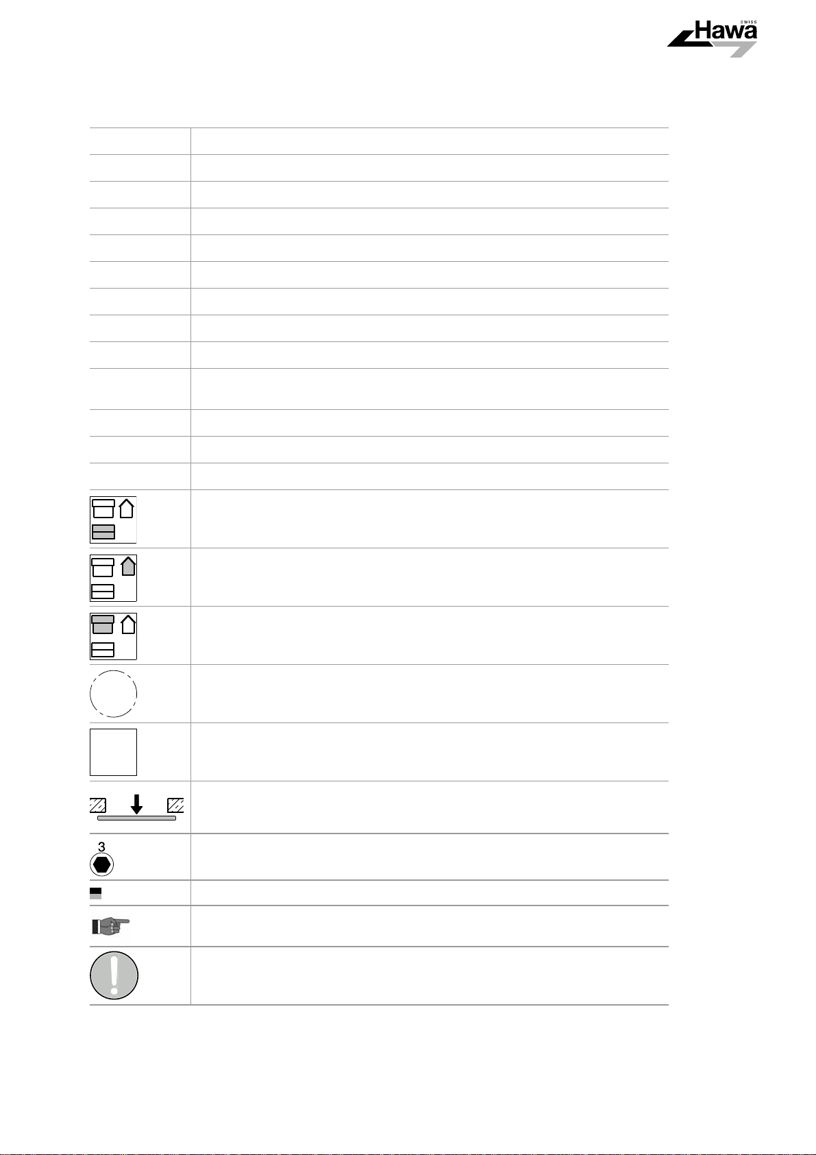
4 Abkürzungen, Symbole / 4Abréviations, symboles / 4Abbreviations, symbols
E
EH
KT
M
N
P
Q
S
T
TA
TB
TH
Z
DE Einschubtiefe / FR Profondeur d'escamotage / EN Slide-in depth
DE Einbauhöhe / FR Hauteur d’encastrement / EN Installation height
DE Korpustiefe / FR Profondeur de corps / EN Cabinet depth
DE Distanz Türgriff / FR Distance de la poignée de la porte / EN Door handle spacing/
DE Konstruktionsmasse / FR Dimensions de la structure / EN Design dimension
DE Distanz / FR Distance / EN Distance
DE Länge / FR Longueur / EN Length
DE Türdicke / FR Epaisseur de porte / EN Door thickness
DE Beschlagstiefe / FR Profondeur de ferrure / EN Hardware depth
DE Topfachsabstand / FR Ecartement d’axe de la charnière invisible / EN Axis-centre
distance of concealed hinge
DE Türbreite / FR Largeur de porte / EN Door width
DE Türhöhe / FR Hauteur de porte / EN Door height
DE Luftzwischenraum / FR Jeu dans l'espacement / EN Air gap
DE Draufsicht / FR Vue de dessus / EN Top view
DE Seitenansicht / FR Vue de cô té / EN Side view
DE Vorderansicht / FR Vue de face / EN Front view
DE Detail / FR Détails / EN Details
DE Option, Variante / FR Option, variante / EN Option, variant
DE Ansichtsseite / FR Vue en projection / EN View side
DE Werkzeugnummer, Werkzeugart / FR Numéro d’outil, type d’outil /
EN Tool number, tool type
DE Hawa Teile / FR Éléments Hawa / EN Hawa components
DE Praxisbezogene Informationen und Tipps / FR Informations et astuces pratiques /
EN Practical information and tips
DE allgemeines Gebotszeichen / FR Signal d’obligation général / EN General mandatory sign
8

HAWA-Concepta 40/50
DE Die in dieser Montageanleitung verwendeten Symbole für sicherheitsrelevante Hinweise (Gefahrenhinweise) haben folgende
Bedeutung:
FR Les symboles utilisés dans ces instructions de montage pour les indications importantes en matière de sécurité (indications de
dangers) ont les significations suivantes.
EN The symbols for notes relevant to safety (hazard warnings) as used in these assembly instructions have the following meanings.
VORSICHT / ATTENTION / CAUTION
DE Vorsicht: Kennzeichnet eine Gefährdung mit geringem Risiko, die leichte oder mittlere Körperverletzung oder Sachschäden zur
Folge haben kann.
FR Prudence : Caractérise un danger de risque faible, susceptible d’entraîner des dommages matériels ou des blessures corporelles
légères à moyennes.
EN Caution: Indicates a hazard with low risk that can result in light to moderate injury or material damage.
9
HAWA-Concepta 40/50
5Übersichten / 5Aperçus généraux / 5Overviews
5.1
DE Übersicht: Anlage links
FR Aperçu général : Installation à gauche
EN Overview: Left-hand system
10
HAWA-Concepta 40/50
5.2
DE Übersicht: Connector 55 (optional)
FR Aperçu général : Connector 55 (en option)
EN Overview: Connector 55 (optional)
DE Verbindungsprofil Connector zu HAWA-Concepta 40/50, siehe Montageanleitung 23227.
FR Profil de raccordement Connector pour HAWA-Concepta 40/50, voir instructions de montage 23227.
EN Connecting profile Connector to HAWA-Concepta 40/50, see installation instructions 23227.
11

HAWA-Concepta 40/50
5.3
DE Übersicht: Connector 110 mit und ohne Sockel (optional)
FR Aperçu général : Connector 110 avec et sans socle (en option)
EN Overview: Connector 110 with and without plinth (optional)
DE Verbindungsprofil Connector zu HAWA-Concepta 40/50, siehe Montageanleitung 23227.
FR Profil de raccordement Connector pour HAWA-Concepta 40/50, voir instructions de montage 23227.
EN Connecting profile Connector to HAWA-Concepta 40/50, see installation instructions 23227.
1* DE Sockelblende demontierbar / FR Cache de socle démontable / EN Removable plinth cover
12

HAWA-Concepta 40/50
5.4
DE Übersicht: Zwei einliegende Dreh-Einschiebetüren
FR Aperçu général : Deux portes pivotantes/escamotables intégrées au corps
EN Overview: Two inset pivot sliding doors
13
HAWA-Concepta 40/50
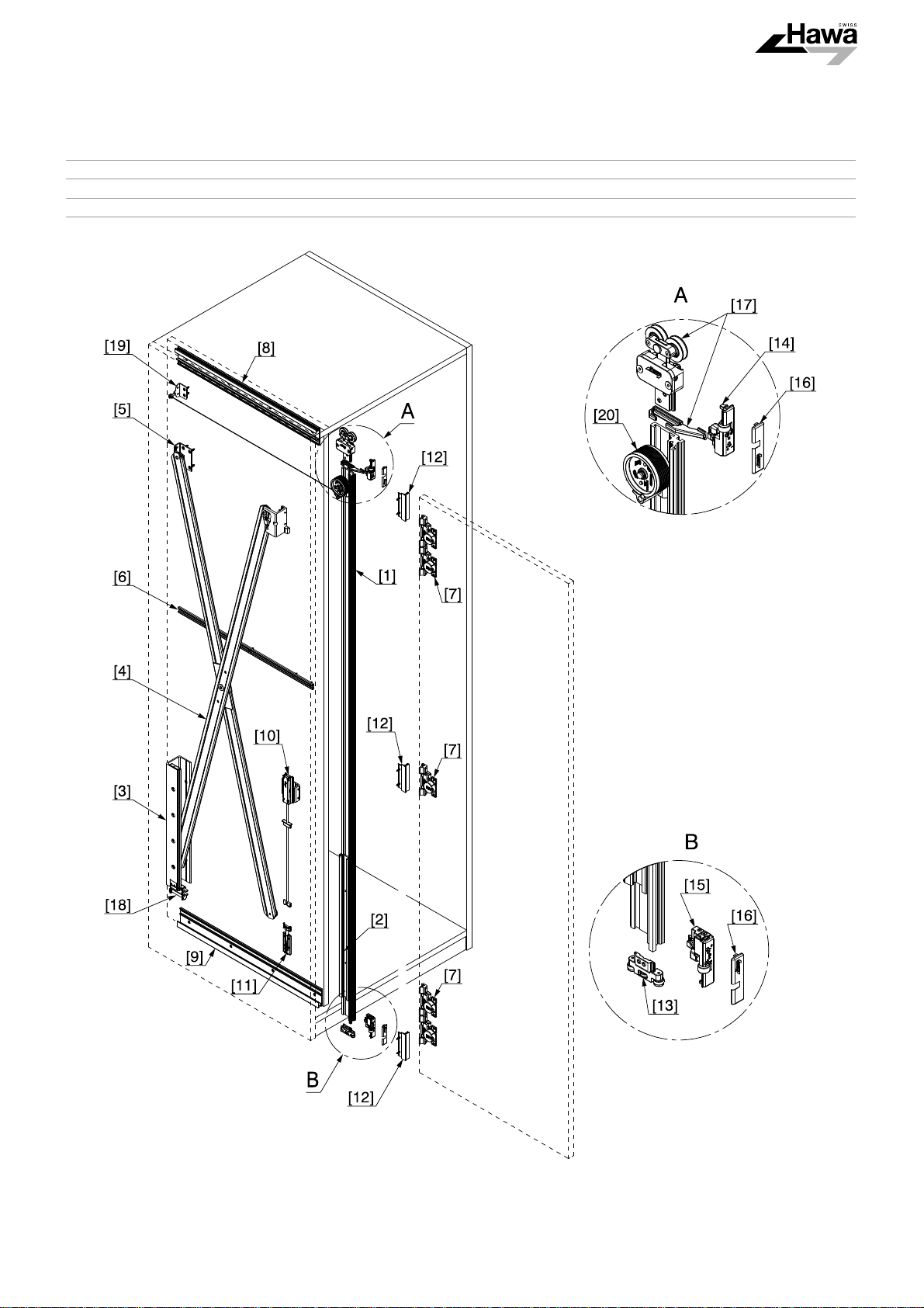
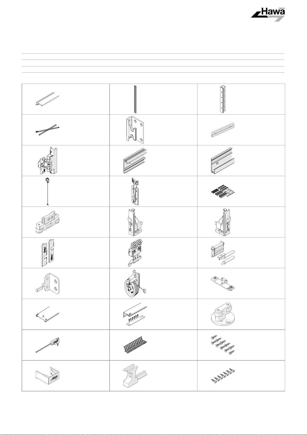
5.5
DE Übersicht: Positionsnummern
FR Aperçu général : Des numéros de position
EN Overview: Position numbers
[1] 22056
22057
[4] 22594 [5] 25855 [6] 22861
[7] 22306 [8] 24528 [9] 24535
[10] 24660 [11] 25828 [12] 25815
[13] 25656 [14] 24624 [15] 24625
[2] 25592 [3] 25596
[16] 24739 [17] 24955 [18] 25862
[19] 25836 [20] 25795
25796
[22] 23223
23224
13164 22451 25935
25808 25809 25562
[23] 23221
23222
[21] 23225
[24] 25680
14

HAWA-Concepta 40/50
6 Planung / 6Planification / 6Planning
6.1
DE Planung: Türe einliegend
FR Planification : Porte intégrée au corps
EN Planning: Inset doors
1* DE Seite demontierbar / FR Côte démontable / EN Removable side
15
HAWA-Concepta 40/50
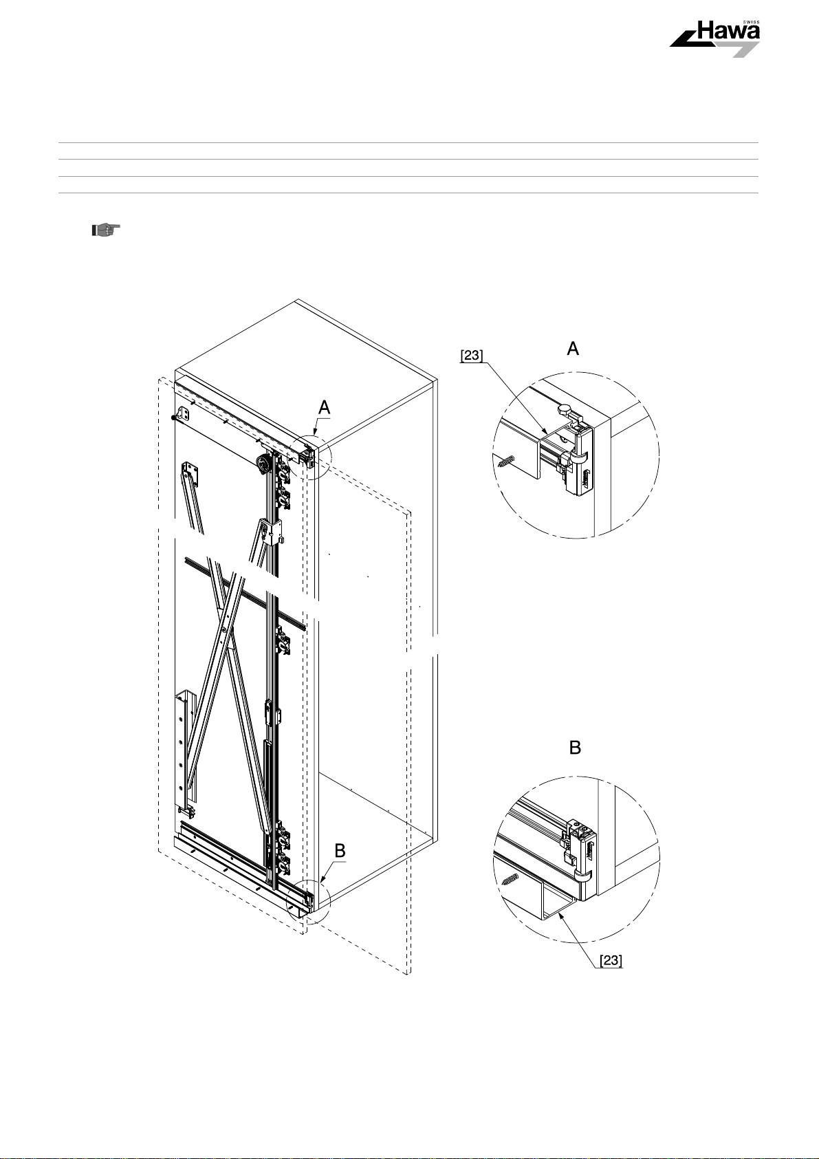
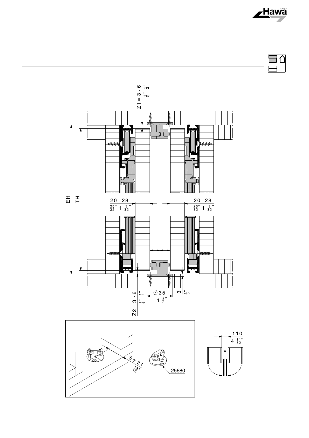
6.2
DE Planung: Führung für zwei einliegende Dreh-Einschiebetüren
FR Planification : Guide pour deux portes pivotantes/escamotables intégrées au corps
EN Planning: Guide for two pivot sliding doors
16

HAWA-Concepta 40/50
6.3
DE Planung: Türe auf Boden und Oberboden aufschlagend mit Connector 55
FR Planification : Porte allant du sol au plafond avec Connector 55
EN Planning: Doors closing against base and top section with Connector 55
17
 Loading...