

Page 1
INSTALLATION INSTRUCTIONS KK-K9-F12-K
2000-2006 FORD EXCURSION
TOOLS REQUIRED:
Power Drill
Standard & Metric Socket Sets
Phillips Screw Driver
7/16” Wrench
Wire Cutters / Crimping tool
HARDWARE: Some of this hardware is already attached.
QTY:
28 ¼-20 X ½” Stainless carriage bolts GSM 32022
30 ¼-20 X ¾” Stainless carriage bolts GSM 32024
64 ¼-20 Serrated nuts GSM 30023
6 ¼-20 X ¾” Hex head Cap Screw Zinc GSM33001
14 ¼” X 1 ½” Hex head lag screw GSM 33062
36 #12 X ¾” Stainless sheet metal screws GSM 34177
24 #10 X ¾” Stainless sheet metal screws GSM 34170
22 #10 X ½” Stainless sheet metal screws GSM 34169
6 #10 X ¾” Sheet metal screws GSM 33195
20 #10 X ½” Sheet metal screws GSM33194
1 Tube Silver Caulk PRM 97343
1 46” X 45 1/2” Rubber Mat KNM01029-SUV
11 1/2 feet Adhesive Molding
SUB ASSEMBLY:
INSTALLATION:
DESCRIPTION: PART #:
• Dome light with wire
• Tunnel edge molding
• Install exhaust fans (Optional). If locating in custom
location drill 4 ½” hole into desired location of K-9
housing. Mark and drill 3/16” mounting holes to
attach fan using (4) 10/32” X ½” machine screws and
10/32” keps nuts. Then mark and drill 3/16” holes to
mount fan guard using 10/32” X ½” machine screws
and 10/32” keps nuts.
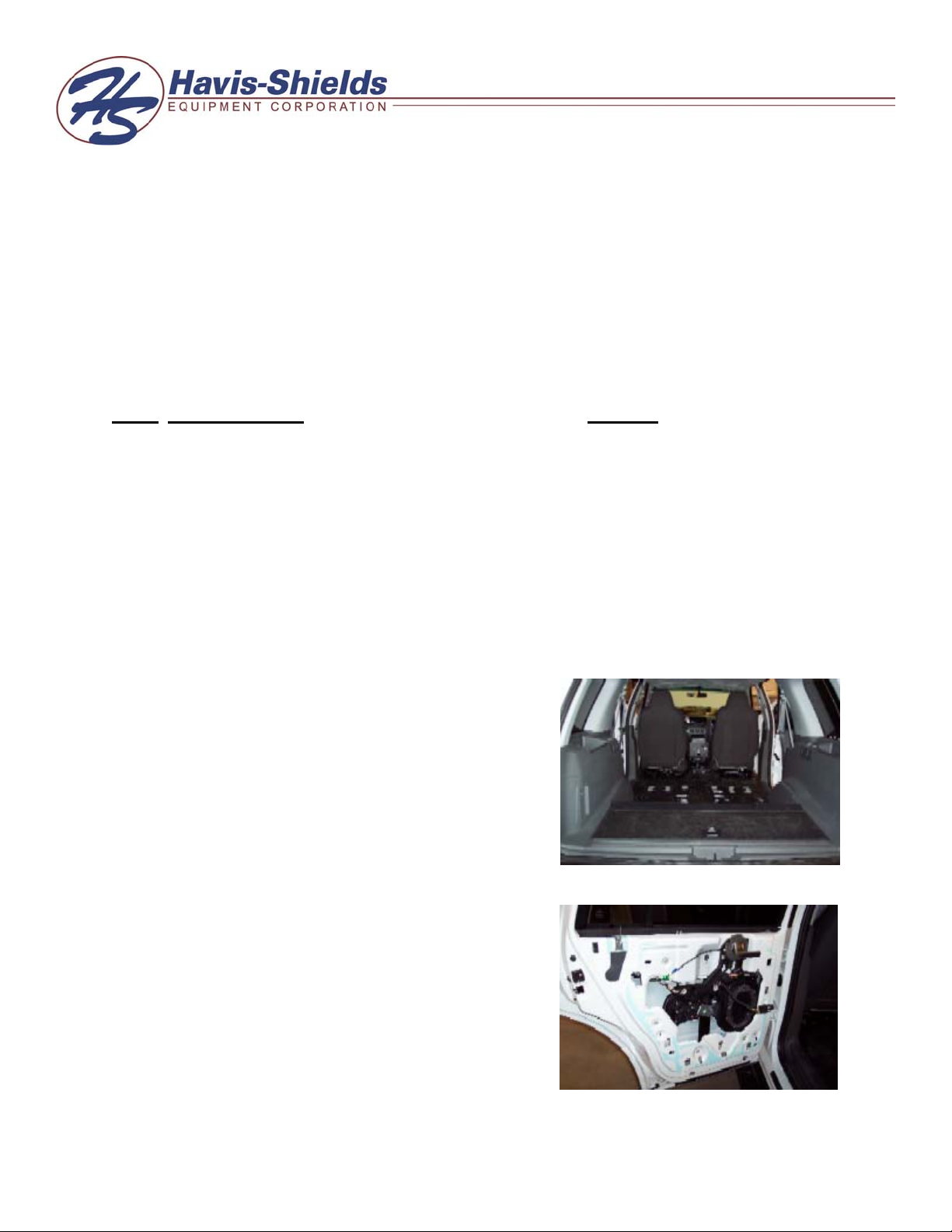
1. Remove interior:
• Remove rear seats
• Remove rear seat belt assembly
• Remove top, and bottom plastic rear trim caps
Ratchet Wrench With 6” Extension
Torx Bit Set
4 ½” Hole Saw (Exhaust Fan Option)
Caulk Gun
Page 2
2. Remove rear OEM door panels:
• Remove speaker, door handle, and lock
• Remove switch assembly from plastic housing (leave
plug on switch)
Note: if doors have electric door switches, they must be reattached to
original plug assembly. Switch assembly must then be wired-tied
down so it does not interfere with window or door latch operations
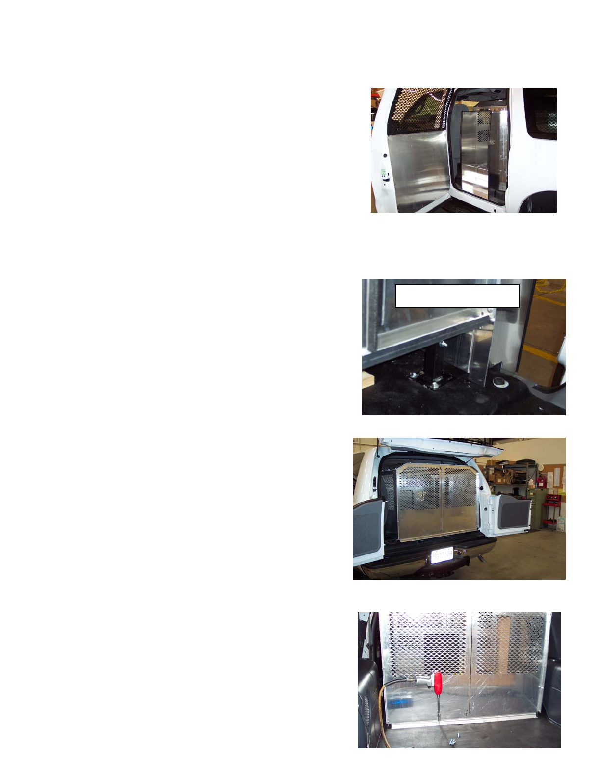
3. Install mounting legs:
• Using ¼-20 x ¾” carriage bolts attach mounting legs
to floor of vehicle using 1/4” x 1 ½” hex head lag screws.
Note: keep nuts loose at this time. And set legs at 6 1/2” high.
4. Slide in K-9 main housing:
• Slide in main housing.
• Housing should be 48 ½” from rear plastic sill to
rear mounting flange.
• Mount legs to housing loosely, using ¼-20 x ¾”
carriage bolts.
• Mount rear support to bottom of rear housing using
(6) ¼-20 x ¾” hex head cap screw.
5. Install tunnels and fillers:
• Loosely attach side tunnels to main housing using
¼-20 x ¾” carriage bolts and ¼-20 x ½” carriage
bolts.
• Place sill plate and cover step in tunnels and
mount with #12 x ¾” stainless sheet metal screws.
6. Housing final step:
• Center housing so cover steps are even on both
sides.
• Mount rear housing to vehicle with ¼” x 1 ½” hex
head lag screw.
• Tighten all loose bolts on tunnels and legs.
Note: If 32” inch long K-9 kit is being installed, a 10”
rear floor extension must be used. (provided with 32”
kits)
Front Driver Side Leg
KK-K9-F12-K-INST-6-06
Page 2
Page 3

7. Door panels and window guards:
• Center door panels so edges do not hang over.
• Attach to door with #10 x ½” stainless sheet metal screws.
Note: window guards have holes around perimeter for permanent mounting. These holes are not used
with hinge kit! They also come flat in shipping. The guard must be pre-bent so it fits tight against the door
window frame.
• Hold window guard with pre-assembled hinge and upper bracket onto window frame.
• Make sure guard is centered on window.
• Attach hinge to lower door panel with #10 x ½” sheet metal screws.
• Mark upper aluminum bracket location on
window frame and remove from window guard.
• Attach aluminum bracket onto window frame with
#10 x ½” sheet metal screws.
• Apply adhesive molding to inner side of window
guard.
• Hinge up window guard and reattach to bracket
with #10 x ½” stainless machine screws and #10
stainless flat washers.
Note: this is for easy window cleaning.
8. Final steps:
• Mount dome light (fan if necessary) switch box as
desired. A switch box is provided so switch can
be mounted to K-9 housing in various locations.
(Topside of tunnel housing works very well).
Wire to 12-volt power source.
• Sheet metal seams and gaps need to be carefully
silicone at floor area. Proper sealing of
compartment will eliminate water from getting
under the K-9 unit.
• Allow silicone to dry overnight before placing in
rubber floor mat.
Upper Window Bracket
Adhesive Molding
KK-K9-F12-K-INST-6-06
Page 3
 Loading...