

Page 1
INSTALLATION INSTRUCTIONS for KK-C-VAK
CHEVROLET VAN REAR AIR VENT ADAPTER KIT
TOOLS REQUIRED
Screw Driver Set
Ratcheting Wrench Set
Standard Socket Set
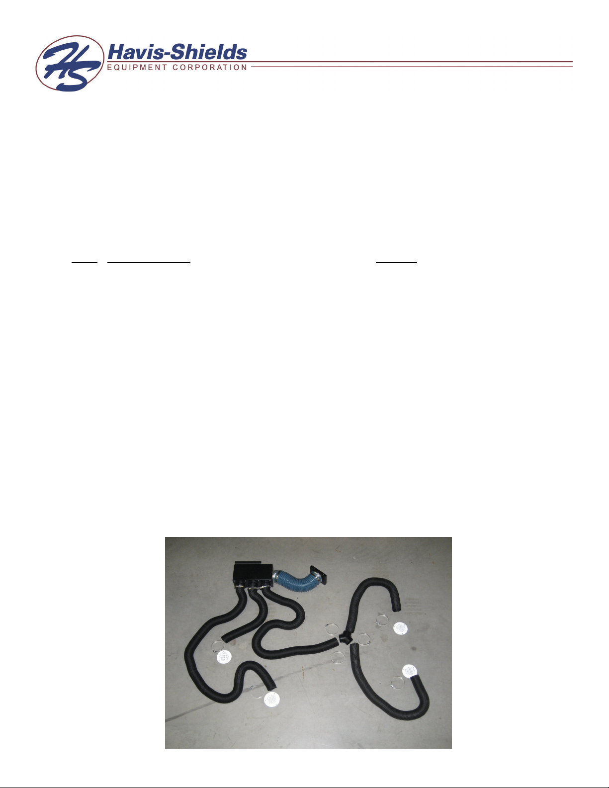
HARDWARE / COMPONENTS:
QTY DESCRIPTION PART #
1 Heat/Cool Adaptor box assembly KKM01152
1 Chevy Heat/Cool Box mounting channel KKM01147
1 Chevy Rear Air Hose Adapter KKM01148
10 Hose Clamps 3” GSM20045
2 4” Hose Clamps GSM20042
1 4” Diameter Hose GSM40100
4 Vent cover w/ hose adapter assembly KKM0403-001
1 2 ½” “Y” Duct Connector PRM97483
1 2 ½” Air Duct Hose 8 foot length PRM97475
1 2 ½” Air Duct Hose 7 foot length PRM97475
1 2 ½” Air Duct Hose 6 foot length PRM97475
2 2 ½” Air Duct Hose 4 foot length PRM97475
20 #10 X ¾” Sheet Metal Screws GSM33195
20 #10 Star Washers GSM31034
20 #10 x ¾” Flat Head Sheet Metal Screws GSM34151
20 15” Wire Tie GSM20036
:
Power Drill
Drill Bit Set
Safety Goggles
Page 2
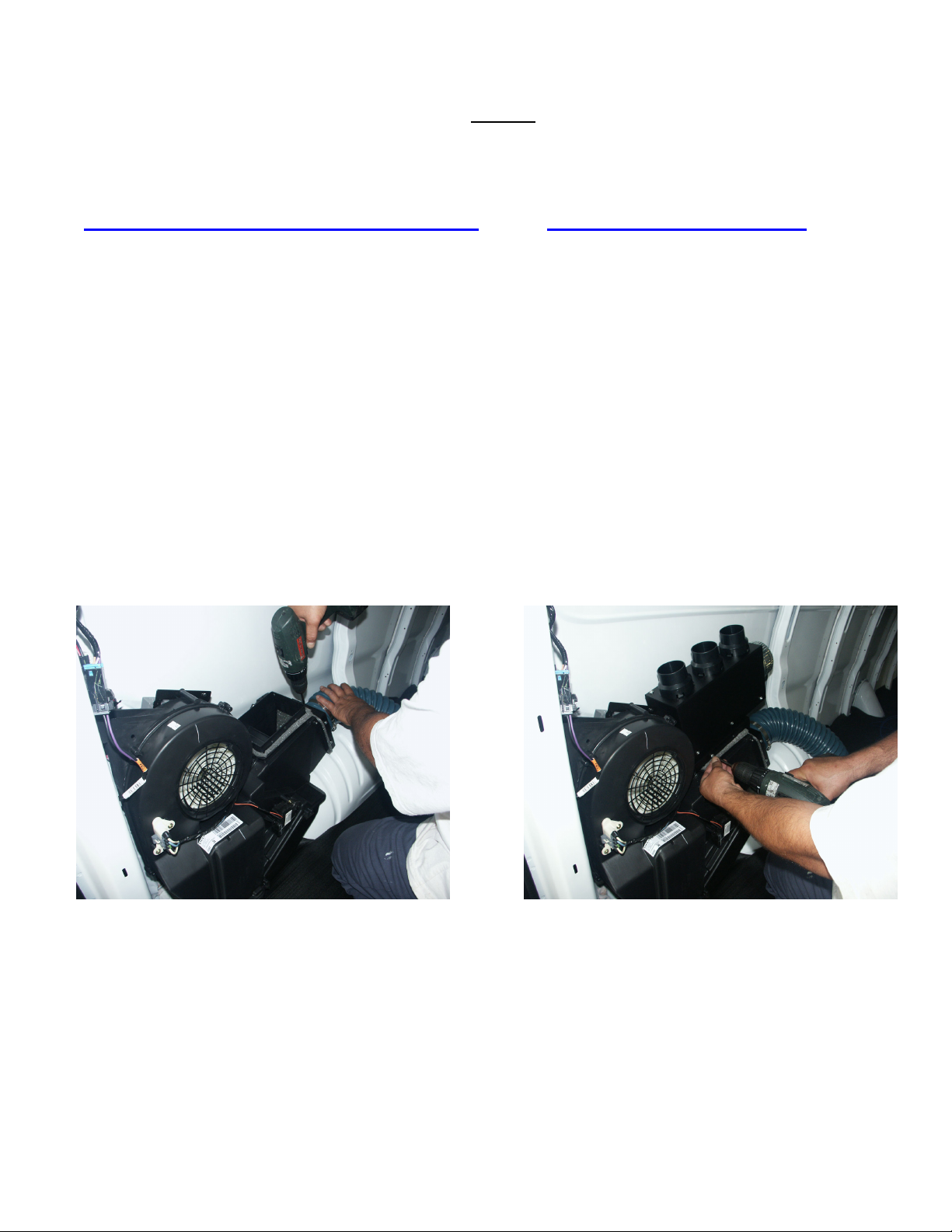
Connect Plenum (rectangle blower adaptor)
. blower ducts using #10 x ¾”
There are two (2) ducts on the factory HVAC
unit. One at rear is for air conditioning and
one forward is for heat. The 4” blue hose
Always!
Read all instructions before installing any Havis-Shields Equipment Corp products.
Check for obstructions (Wire, brake lines, fuel tank, etc.) before drilling any holes!
Use hardware provided with install kit
For product support, visit the Install Instructions Section of our website at
http://havis.com/Installation/Installation.html, email technicalsupport@havis.com or call
1-800-524
Note: This procedure must be done PRIOR to the Kwik Kit installation and is
recommended to check the flow of Air through the hoses prior to installation of KwikKit unit.
SUBASSEMBLY:
1. Remove all necessary parts from shipping packages and verify parts.
2. Remove AC and Heat plastic vents from OEM - HVAC blower ducts.
3. If vehicle has full rear trim, you must remove trim panels around the OEM - HVAC unit
including ductwork / headliner. NOTE: The front portion of headliner can be cut off and reused
as front ceiling trim after complete kit is installed.
INSTALLATION:
connects heat into the new plenum.
to the O.E.M
Sheet Metal Screws and #10 star washers
KK-C-VAK_INST_10-07
.
Page 3

Route HVAC 2 1/2” blower hoses to the
where they will be installed into the
mounting.
Attach the “Y” duct hose adaptor to
the 8 foot front duct hose and
connect both 4 foot hoses from “Y”
to vents in driver and passenger side
front ceiling. This will provide a
Route hose straight up from the HVAC unit
approximate locations with tape along
ceiling
ceiling insert after Kwik-Kit insert is
installed. Mount hoses with wire ties at
wall and ceiling corners only. Leave
enough slack to reach hoses for permanent
total of four ceiling vents.
and tie tight to corner of the van
When routing the hoses, tie together using
15” wire ties, to keep a neat and tight fit to
the wall of the vehicle.
This will minimize the risk of damage when
installing Kwik kit
KK-C-VAK_INST_10-07
Page 4

uminum insert is installed and tested,
attach cover plate to bench / wall to cover
OEM Rear AC/Heat Unit using #10 Sheet
Check that airflow through hoses is
With hoses routed to locations, proceed
working properly.
to install Kwik-Kit unit until you come
to the ceiling instructions. Be sure not
to puncture the hoses with screws, drill
bits, etc…
Attach ceiling pieces on Kwik-Kit,
routing hoses into the corresponding
holes in Kwik-Kit ceiling. Pull through
to minimize slack.
Check airflow again.
After Al
metal screws.
During Kwik-Kit installation you will
be prompted to return to the KK-CVAK instruction to attach the hose to
the vent adapter brackets. Route hose
into ceiling holes and cut off any extra
slack.. Attach the hose to the vent
bracket using a 3” hose clamp
Align the three mount holes of the vent adapter cover
with the pre-punched holes in ceiling.
Attach each vent to ceiling using #8 x 3/8” flat head
sheet metal screws.
(Screws included with standard Kwik-Kit hardware)
KK-C-VAK_INST_10-07
 Loading...