

Page 1

INSTALLATION INSTRUCTIONS KK-K9-F14-K
K9 TRANSPORTATION SYSTEM
2003-2009 EXPEDITION
TOOLS REQUIRED:
Power Drill
Drill Bit Set
Standard & Metric Socket Sets
Phillips Screw Driver
Open End Wrench Set
HARDWARE:
QTY: DESCRIPTION: PART #:
28 ¼” x ½” Stainless carriage bolts GSM32022
8 ¼” x ¾” Stainless carriage bolts GSM32024
64 ¼” flanged serrated nuts GSM30023
6 ¼” x ¾” Hex head cap screw GSM33001
6 ¼” x 1 ½” Hex head lag screw GSM33062
36 #12 x ¾” Stainless sheet metal screws GSM34177
24 #10 x ¾” Stainless sheet metal screws GSM34170
12 #10 x ½” Stainless sheet metal screws GSM34169
10 #10 x ¾” Stainless machine screws GSM34098
6 #10 x ¾” Sheet metal screws GSM33195
1 Tube silver caulk PRM97343
1 46” x 45 ½” Rubber Floor mat KNM01029-SUV
10 #10 x ½” Flat head sheet metal screws GSM33150
Wire Cutters / Crimping tool
Ratcheting Wrench Extension
Torx Bit Set
4 ½” Hole Saw (Exhaust Fan Option)
Caulk Gun
Always!
¾ Read all instructions before installing any Havis-Shields Equipment Corp products.
¾ Check for obstructions (Wire, brake lines, fuel tank, etc.) before drilling any holes!
¾ Use hardware provided with install kit
For product support, visit the Install Instructions Section of our website at
http://havis.com/Installation/Installation.html, email technicalsupport@havis.com or call 1-800-
524-9900.
Page 2
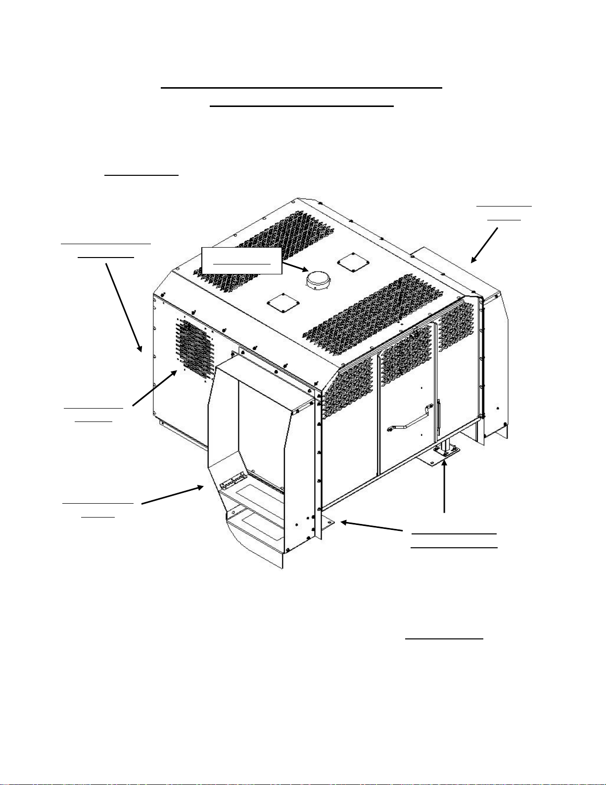
Assembled K9 Transportation System for
Rear of Unit
Rear Support Plate
(not shown)
2003-2009 Ford Expedition
Driver Side
Tunnel
Dome Light
Location for
11” Fan
(PRM97466)
Passenger Side
Tunnel
Mounting Legs &
Hold Down Plates
Front of Unit
2
KK-K9-F14-K_INST_11-08
Page 3
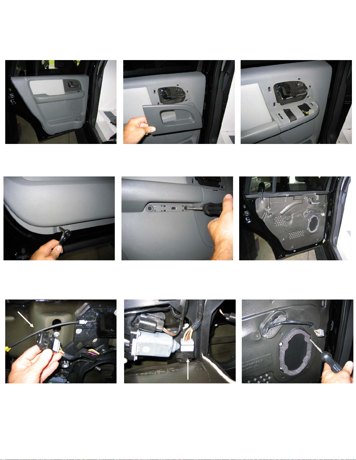
SUBASSEMBLY:
Note: If doors have electric door switches, they must be reattached to original plug assembly. Switch
assembly must then be wired-tied down so it does not interfere with window or door latch operations.
View of Expedition door panel
Remove plastic trim piece. Metal
clips hold on trim
ove hex head screws holding
Rem e trim piece coverin
lower section of door panel
Remov g torx
screws under door panel armrest
and remove screws
Remove window/lock switch
assembly from door
Remove plastic door panel
Remove window switch and
reconnect. Wire tie switch in safe
location.
Recommended location to
relocate switch
3
Remove spe
aker from door panel.
Remove screws and unplug
KK-K9-F14-K_INST_11-08
Page 4

Remove bolt
Cut on this line
1. Remove the specified bolt and cut o
the line shown lef
2. The upper portion of the c
t.
ut piece
will remain off.
3. Save for vehicle re-sale.
n
Back seat configuration for
Ford Expedition
Remove trim pieces co
seat bolts
4
vering
Remove bolts from seat bases
KK-K9-F14-K_INST_11-08
Page 5

Remove plastic storage compartment
INSTALLATION:
Note: The K9 unit will not slide into rear hatch opening without removing ream d
trim panels. Side tunnels must also be removed.
.
1 Attach floor mounting plates to heig
nuts. (Photos 1 and 2)
2. The holes in mounting plates will line up with OEM seat mount holes. Bolt the plate and leg
assembly to vehicle using OEM seat bolts. Adjust leg height to 7 ¾” inch.
3. Slide K9 main housing into vehicle:
ht adjustable front legs with ¼” x ¾” carriage bolts and serrated
oor
Using factory seat bolts; attach driver
and passenger side mounting plates
and legs as shown above.
Set height at 7 ¾”
Note: Mounting plate
straddles a ridge in the
floor. When bolts are
tightened the plate will
form to the floor.
4
7 ¾”
When positioned properly, holes
in K9 floor will align with holes in
mounting legs.
5
KK-K9-F14-K_INST_11-08
Page 6
. Attach rear support plate to bottom of rear floor lip using ¼” x ¾” hex head bolts. (Photo 3)
4
. Attach top of K9 mounting legs to floor using ¼”
5 x ¾” carriage bolts and serrated nuts. Holes in
floo will line up with ho
les in mounting feet.
6. Loosely attach side turnnels to main housing using ¼” x ¾” and ¼” x ½” carriage bolts.
Note: Use ½”long bolts on double skin and ¾”long on triple skin.
. Housing final step:
7
• Center K9 housing so tunnels are even on
both sides.
• Mount rear housing support to vehicle using
¼ x 1 ½” hex head lag bolts.
• Tighten all loose bolts on tunnels and
legs.
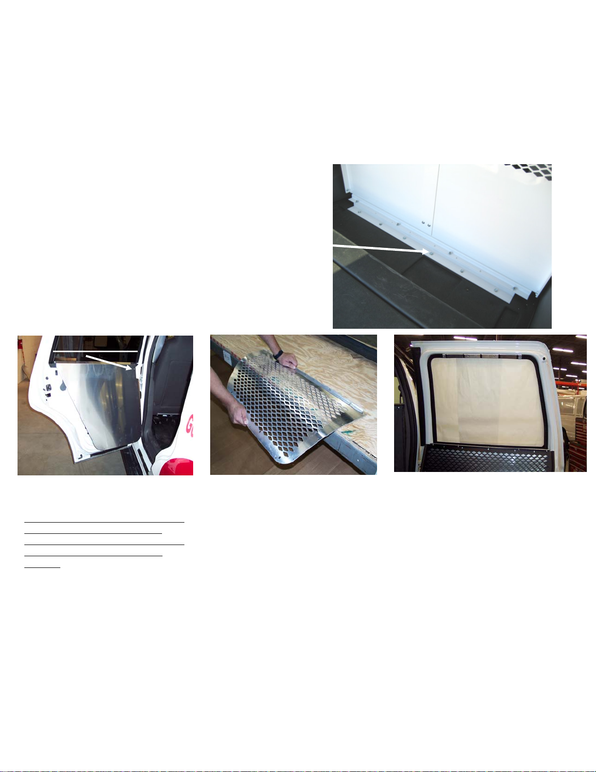
Top Inner Screw
Cent
er door panels so edges do not hang
over. A ach to door with #10 x ½”
tt
stainless sheet metal screws.
Note:
Window guards have holes around
perimeter for permanent mounting.
These holes are not used with hinge style
window kits! They also come flat in
shipping.
The window guard must be prebent so it fits tight against the
contour of the door window
frame. The aluminum guard can
easily be formed at wok bench.
Hold window guard with pre-assembl ed
hinge and upper bracket onto window fra me.
Make sure guard is centered on window.
Attach hinge to lower door panel with #10
½” stainless sheet metal screws. Mark uppe
aluminum bracket location on window fr
and remove from window guard. Attach
upper aluminum bracket onto window fra
with #10 x ½” flat head sheet
metal screws
x
r
ame
me
.
6
KK-K9-F14-K_INST_11-08
Page 7

8. Final Installation Steps:
• Mount dome light switch box. A switch box is pr
housing in various locations. (At topside of
• Wire to 12-volt power source on as preferred.
• Sheet metal seams and gaps need to be SI
compartment will eliminate water from
• Allow silicone to dry overnigh
KK-K9-F14-K Installation Complete
Hinge up window
guard and reattach to
bracket with 10-32 x
½” Stainless machine
screws and #10 Flat
washers.
NOTE: Door panel
fillers are provided for
the Expedition EL.
This is not used for the
standard length
Expedition.
driver-side tunnel housing works well).
LICONED along floor area. Proper sealing of
getting under the K9 unit.
t then place rubber floor mat.
Standard
door panel
ovided so switch can be mounted to K9
7
KK-K9-F14-K_INST_11-08
Page 8

8
KK-K9-F14-K_INST_11-08
 Loading...