

Havis-Shields DS-DELL-101-3, DS-DELL-101, DS-DELL-103, DS-DELL-221, DS-DELL-223 User Manual
Page 1
Owner’s Manual
Havis Rugged Mobile Docking Station
For Dell XFR & ATG Computers
DS-DELL-100 Series / DS-DELL-220 Series
DS-DELL-101
DS-DELL-101-3
DS-DELL-103
DS-DELL-100 Series/200 Series/210 Series
Havis Rugged Mobile Docking Station
For Dell XFR & ATG Computers
DS-DELL-221
DS-DELL-223
www.havis.com
1-800-524-9900
Page 2
Mounting Solutions Computing Solutions Power Management
Solutions
Transport Solutions Lighting Solutions
Product
Catalog
www.havis.com 1-800-524-9900
Before Beginning
(Original Instructions)
Havis is pleased to provide this Owner’s Manual to aid in the proper installation
and use of the DS-DELL-100 Series/220 Series Docking Station for the
Dell XFR & ATG laptop computers.
For questions regarding the set-up of your DS-DELL-100 Series/220 Series Docking
Station, please contact Havis at 1-800-524-9900 or visit www.havis.com for additional
product support and information.
This Owner’s Manual applies to the following Part Numbers:
DS-DELL-101
DS-DELL-101-3
DS-DELL-103
• NEVER STOW OR MOUNT THE DOCKING STATION DIRECTLY IN A VEHICLE
AIRBAG DEPLOYMENT ZONE.
• DO NOT USE COMPUTER WHILE DRIVING.
• READ ALL INSTRUCTIONS THOROUGHLY BEFORE BEGINNING INSTALLATION.
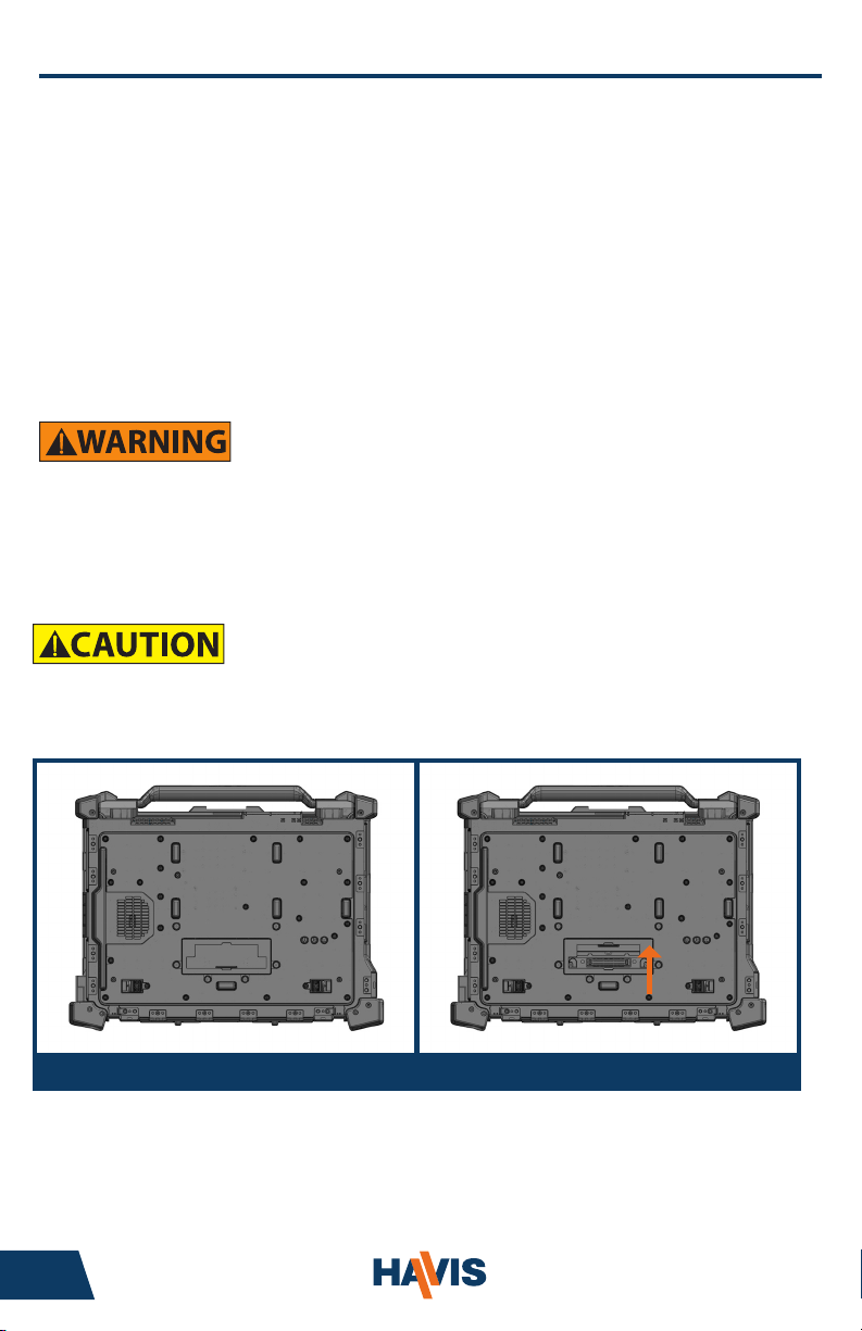
• DO NOT MATE COMPUTER TO DOCKING STATION UNLESS COMPUTER’S DOCKING
CONNECTOR ACCESS DOOR IS FULLY OPEN OR DAMAGE MAY RESULT. (SEE BELOW)
DS-DELL-221
DS-DELL-223
Dell E6420 XFR shown with Connector Access Door in closed position (left) and open position (right)
2 11
Page 3
• FOR SAFE & PROPER SYSTEM FUNCTION, SPECIFIC DOCKING STATION MODELS
MUST BE USED WITH SPECIFIC DELL COMPUTER MODELS.
- DS-DELL-100 SERIES (101, 103, ETC.) DOCKING STATIONS ARE INTENDED FOR USE
WITH DELL E6400, E6410 & E6420 XFR COMPUTERS ONLY.
- DS-DELL-220 SERIES (221, 223) DOCKING STATIONS ARE INTENDED FOR USE
WITH DELL E6400, E6410, & E6420 ATG COMPUTERS ONLY.
- THE PORT COVERS SUPPLIED WITH DELL E6400 & E6410 ATG COMPUTERS
MUST BE REMOVED PRIOR TO DOCKING.
- THE PORT COVERS SUPPLIED WITH DELL E6420 ATG COMPUTER MAY
REMAIN SECURED TO COMPUTER WHILE DOCKING.
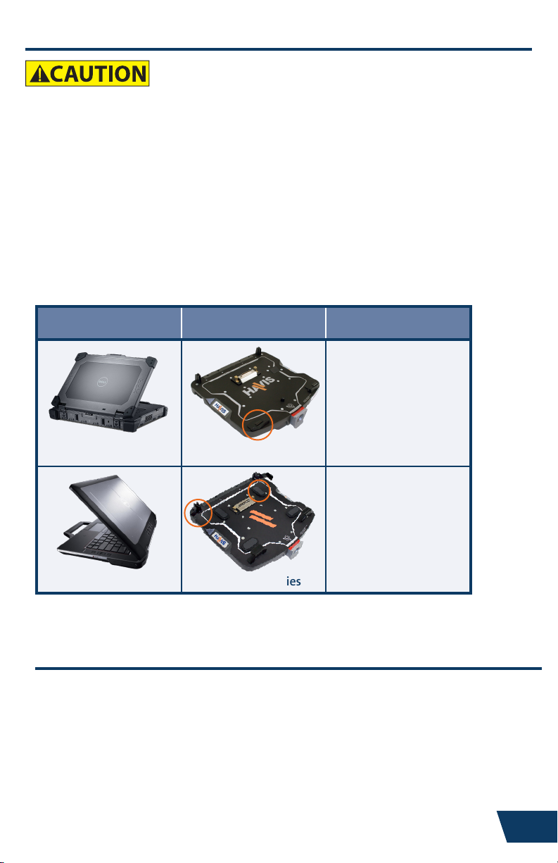
• COMPUTER & DOCKING STATION IDENTIFICATION:
COMPUTER MODEL DOCKING STATION IDENTIFICATION
No Foot Pads on
top plate.
Low prole Front Hooks.
E6400/6410/6420 XFR DS-DELL-100 Series
Foot Pads on top plate.
Macro Alignment
Brackets attached.
E6400/6410/6420 ATG DS-DA-220 Series
Precautions
• Do not place metal objects or containers of liquid on top of the Docking Station
• If a malfunction occurs, immediately unplug the Power Supply and remove the laptop
• Use only the specied Power Supply (Part # LPS-105) with this Docking Station
• Do not store the Docking Station where water, moisture, steam, dust, etc. are present
• Do not connect cables into ports other than what they are specied for
• Do not leave the Docking Station in a high temperature environment (greater than 75°C, 167°F)
for a long period of time
www.havis.com • 1-800-524-9900
Page 4
Table of Contents
Specications
Parts Included
Port Replication Capability
Installation
Cable Management
Operation - Docking
Operation - Undocking
Specications
Power Supply Input 20V DC-In
Dimensions 13.6” ( 34.4 cm) W x 12.7” ( 32.3 cm ) D x 3.7” ( 9.4 cm ) H
Weight 6.6 lbs ( 2.9 kg )
DS-DELL-100 Series Docking Stations for DELL E6400, E6410, E6420 XFR Computers
Operating Environment 0° C to 40° C ( 32° F to 104°F )
Storage Environment -60° C to 75° C ( -76° F to 167° F )
DS-DELL-220 Series Docking Stations for DELL E6400, E6410, E6420 ATG Computers
Operating Environment 0° C to 35° C ( 32° F to 95°F )
Storage Environment -60° C to 75° C ( -76° F to 167° F )
4
5
5
6
7
9
10
DECLARATION OF CONFORMITY FOR CE MARKING
Havis, Inc. declares that their DS-DELL-100 & DS-DELL-220 SERIES DOCKING STATIONS:
Are classied within the following EU Directives:
EU Electromagnetic Compatibility Directive 2004/108/EC, 2009/19/EC
And further conform with the following EU Harmonized Standards:
EN 55022 (2006) + A1 2007, EN 55024: 1998 + A1: 2001 + A2: 2003
EN 50498: 2010
Clause 7.1 Broadband Radiated Disturbances - Quasi-Peak
Clause 7.2 Narrowband Radiated Disturbances - Average
Clause 7.3 Conducted Radiated Disturbances - Severity Level 2
Dated: September 28 , 2011
Position of signatory: Chief Information Officer / Chief Financial Officer
Name of signatory: Steve Ferraro
Signed:
4 9
Page 5

Parts Included
Docking Station
Macro Alignment Brackets
(DS-DELL-220 Series only)
Docking Connector
Lock
Latch Handle
Mounting Bracket
Hardware Kit
This Hardware Kit includes:
1. Zip Ties (4)
2. Keys (2)
3. 1/4”-20 Screws (4)
4. M5 Screws (4)
Tools required for installation:
• 3mm Hex Drive
(For attaching Mounting Bracket to
Docking Station with M5 Screws)
Strain Relief Points
Foot Pads
(DS-DELL-220 Series only)
Front Hooks
Power Button/LED
• 5/32” Hex Drive
(For attaching Mounting Bracket to
Motion Device with 1/4”-20 Screws)
Port Replication Capability
Rearward Connectivity *(Antennas for DS-DELL-101-3 only) Side Connectivity
eS ATA
Mouse
Keyboard
Ethernet
USB 2.0 (x2)
Parallel (DB-25)
VGA
Serial
www.havis.com • 1-800-524-9900
Antennas*
(Wi-Fi, GPS, Cellular)
Display (x2)
(HDMI Dongle Required)
Power Input
Microphone
Headphone
USB 2.0 (x3)
Page 6

Installation
1) Install the Mounting Bracket to the Motion Device using (4) 1/4“-20 screws
(Hardware Kit Item 3). Torque screws to 120 in-lbs (13.4Nm) ± 10%.
NOTE: Numerous hole patterns present in Mounting Bracket will accommodate Havis
Motion Devices as well as most competitors’.
1/4”-20 Screws
Mounting Bracket
Typical Motion Device Example
(not included)
2) Lower the Docking Station to the Mounting Bracket as shown and secure with
(4) M5 screws (Hardware Kit Item 4). Torque screws to 25 in-lbs (2.8 Nm) ± 10%.
M5 Screws
NOTE: We recommend applying a drop of medium strength (blue)
thread locking adhesive to the threads of all fasteners.
6 7
Page 7

Cable Management
1) Tip the Docking Station forward to a position that is comfortable to work with.
2) Install all cables that are necessary for computing needs.
3) Use Zip Ties (Hardware Kit Item 1) to strain relieve cables to the Strain
Relief Points at rear of Docking Station.
4) Gather all cables to one side and tie off to unused holes on underside
of Docking Station.
Insert as many zip ties as
necessary to secure cables.
www.havis.com • 1-800-524-9900
Page 8

Cable Management (continued)
5) Create a service loop with cables to ensure that no tension is on the
connectors and to enable intended motion.
6) Tie off cables onto a stationary part of the mounting system.
(Mounting system not included with Docking Station)
This loop must be large enough
to allow full range of expected
rotation and extension without
stressing connections.
Collect cables to secure
to the mounting system
(Note: mounting system not included)
8 5
Page 9

Operation - Docking
• DO NOT MATE COMPUTER TO DOCKING STATION UNLESS COMPUTER’S DOCKING
CONNECTOR ACCESS DOOR IS FULLY OPEN OR DAMAGE MAY RESULT.
• DO NOT FORCE LAPTOP ONTO DOCKING STATION. IF THERE IS RESISTANCE,
CHECK ALIGNMENT OF COMPUTER ON DOCKING STATION.
1) To load the computer, rst ensure Docking Station is unlatched by pushing
the Lock to release the Latch Handle. Once Docking Station unlatches, release
pressure on Lock to allow the Latch Handle to extend fully.
Note: Red warning label on Latch Handle is visible when fully extended.
Lock
Latch Handle
2) With rear of computer elevated, load front of computer into Docking Station
by aligning Front Hooks with the appropriate recesses in the computer case.
RearFront
3) Lower rear of computer onto Docking Connector. Blue Port Replication LED
will illuminate once computer is properly seated.
4) With computer seated on Docking Station, push in the Latch Handle to
secure computer to Docking Station.
RearFront
Port Replication LED
Latch Handle
• LED INDICATORS DO NOT INDICATE PHYSICAL SECURITY
• DOCKING STATION MUST BE LATCHED AT ALL TIMES
WHILE VEHICLE IS IN MOTION
www.havis.com • 1-800-524-9900
Page 10

Operation - Docking (continued)
5) For theft deterrence, secure computer by locking Docking Station with
supplied key (Hardware Kit Item 2).
Lock
6) Power on computer. The Laptop Power Button LED will illuminate blue to
indicate proper system function. Once docked, the Laptop Power Button may
be used to power computer on/off.
Laptop Power
Button / LED
Operation - Undocking
1) If previously locked, unlock Docking Station using supplied key.
Lock
2) To release Latch Handle, press in the Lock, and the Latch Handle will spring
open to the Unlatched position.
Note: Red warning label on Latch Handle is visible when fully extended.
Lock
Latch Handle
3) Once unlatched, grab both sides of computer and carefully lift out of
Docking Station, rear end rst.
RearFront
10 3
Page 11

Related Products
Mounting Solutions Computing Solutions Power Management
Solutions
Transport Solutions Lighting Solutions
Product
Catalog
www.havis.com 1-800-524-9900
Havis offers a wide variety of accessory products specically for
use with the DS-DELL-100 & DS-DELL-220 Series Docking Station.
For more information or to order, please visit www.havis.com.
LPS-105
90W Power Supply
External power supply and cable for Dell Laptops with
cigarette lighter adaptor.
DS-DA-408
Screen Stiffener
Secure your laptop screen to prevent excess wear and
reduce vibration while in use.
DS-DA-102
USB Powered Light
Soft red LED light illuminates the laptop keyboard
for night viewing.
DS-DA-208
Card Reader Mounting Bracket
Mount an E-Seek Model 250 card reader to the side
of the Docking Station.
(Bracket can be customized for other Card Reader Models)
Interactive Online Catalog
Our interactive catalog is an easy-to-use, full color,
online version of our printed catalog.
Visit www.haviscatalog.com for direct access
to the Interactive Catalog.
www.havis.com • 1-800-524-9900
Page 12

Havis, Inc.
75 Jacksonville Road, PO Box 2099
Warminster, PA 18974
47801 Anchor Court
Plymouth, MI 48170
www.havis.com 1-800-524-9900
DS-DELL-100-220_OMN_9-11
 Loading...