

Page 1

INSTALL INSTRUCTIONS C-TM-IMP-1
HEAVY DUTY TRAK MOUNT
2006-2009 CHEVROLET IMPALA
TOOLS REQUIRED:
Ratcheting wrench Standard Socket set
HARDWARE:
QTY DESCRIPTION PART #
1 18” Length Extrusion CM93055-2
1 12” Length Extrusion CM93055-1
1 Transmission Hump Bracket (no holes drilled) C-B43
1 Rear Extrusion Bracket CM001380
1 Extrusion Adapter Bracket CM001379
12 ¼” Serrated Nut GSM30023
12 ¼ x ¾” Hex Head Bolt GSM33001
6 ¼” x ¾” Phillips pan head machine screws GSM33124
6 ¼” Flat washers GSM31000
2 #10 x ¾” Phillips pan head machine screws GSM33119
6 ¼” x ¾” Hex Head Lag Bolts GSM33060-1
Open-end wrench set
Screwdriver Set
C-B42
¾ Read all instructions before installing any Havis-Shields Equipment Corp products.
¾ Check for obstructions (Wire, brake lines, fuel tank, etc.) before drilling any holes!
¾ Use hardware provided with install kit
¾ For product support, visit the Install Instructions Section of our website at
http://havis.com/Installation/Installation.html, email technicalsupport@havis.com or call
1-800-524-9900.
C-TM-IMP-1
Transmission
Hump Bracket
(C-B43)
Guide bracket
Always!
18” Length
Extrusion
12” Length
Extrusion
Under seat
adapter bracket
Extrusion
Adapter Bracket
Rear Extrusion
Bracket
Page 2
SUB ASSEMBLY:
1. Confirm receipt of all hardware and components.
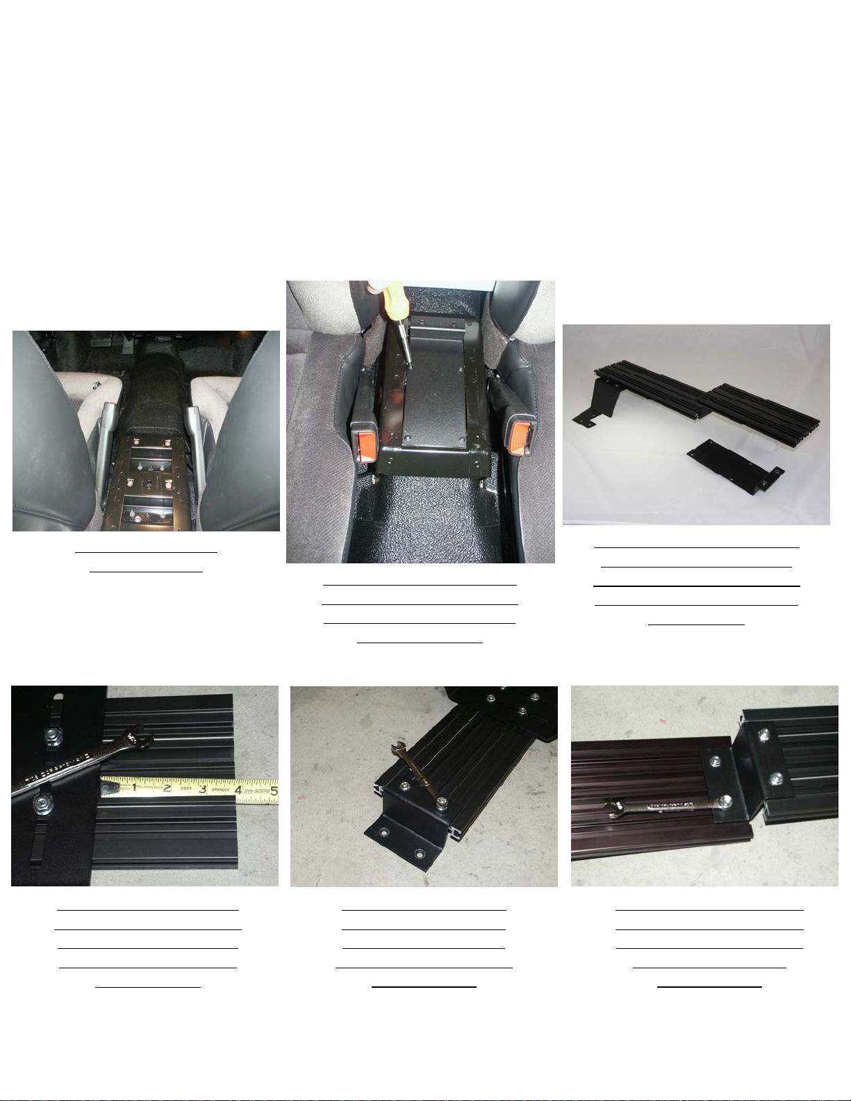
2. Remove partial OEM cup-holder/console located on the transmission hump.
Note: Do not remove metal housing attached to this partial console. This piece is meant to strengthen the
vehicles crumple zone and must not be removed.
INSTALLATION:
View of partial OEM
console removed
Attach C-B43 transmission
hump bracket to 18” section
of extrusion using (4) ¼” x
¾” bolts and serrated nuts.
(7/16” Wrench)
Attach rear extrusion bracket
(CM001380) to vehicle using
factory screws from, “partial
console,” removal.
Attach extrusion adapter
bracket to 18” section of
extrusion using (2) ¼” x
¾” bolts and serrated nuts.
(7/16” Wrench)
Sub-assemble C-B43 (only the
piece shown), 18” portion of
trak, extrusion adapter bracket,
rear extension bracket and 12”
portion of trak
Attach the extrusion adapter
bracket to the 12” section of
extrusion using (2) ¼” x ¾”
bolts and serrated nuts.
(7/16” Wrench)
2
C-TM-IMP-1_INST_11-08
Page 3
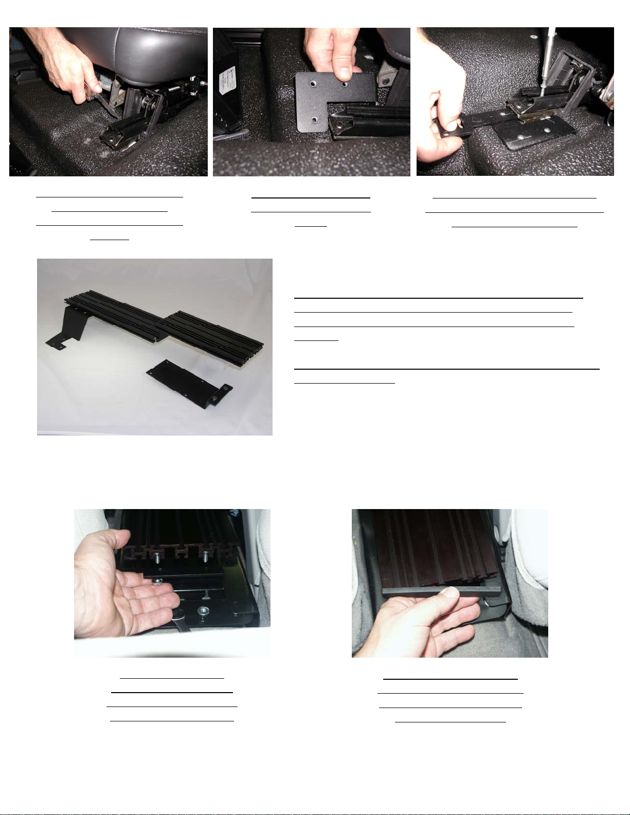
Cut floor mat, next to the seat
rail to allow Under seat
support bracket to slide under
seat rail
Slide under seat support
brackets into position as
shown
1. Position sub-assembled transmission hump bracket, 18”
portion of trak, extrusion adapter bracket, rear extension
bracket and 12” portion of trak to the under seat & guide
brackets.
2. Loosely attach assembly using ¼-20 x ¾” Phillips machine
screws and washers.
Slide guide brackets into seat rail
and loosely attach #10 x ¾” Phillips
pan head machine screws
Attach rear extrusion
bracket to 12” portion of
extrusion using (2) ¼-20 x
¾” bolts and serrated nut
Tighten all loose hardware.
Insert necessary hardware for
consoles and accessories and
attach plastic end caps
3
C-TM-IMP-1_INST_11-08
Page 4
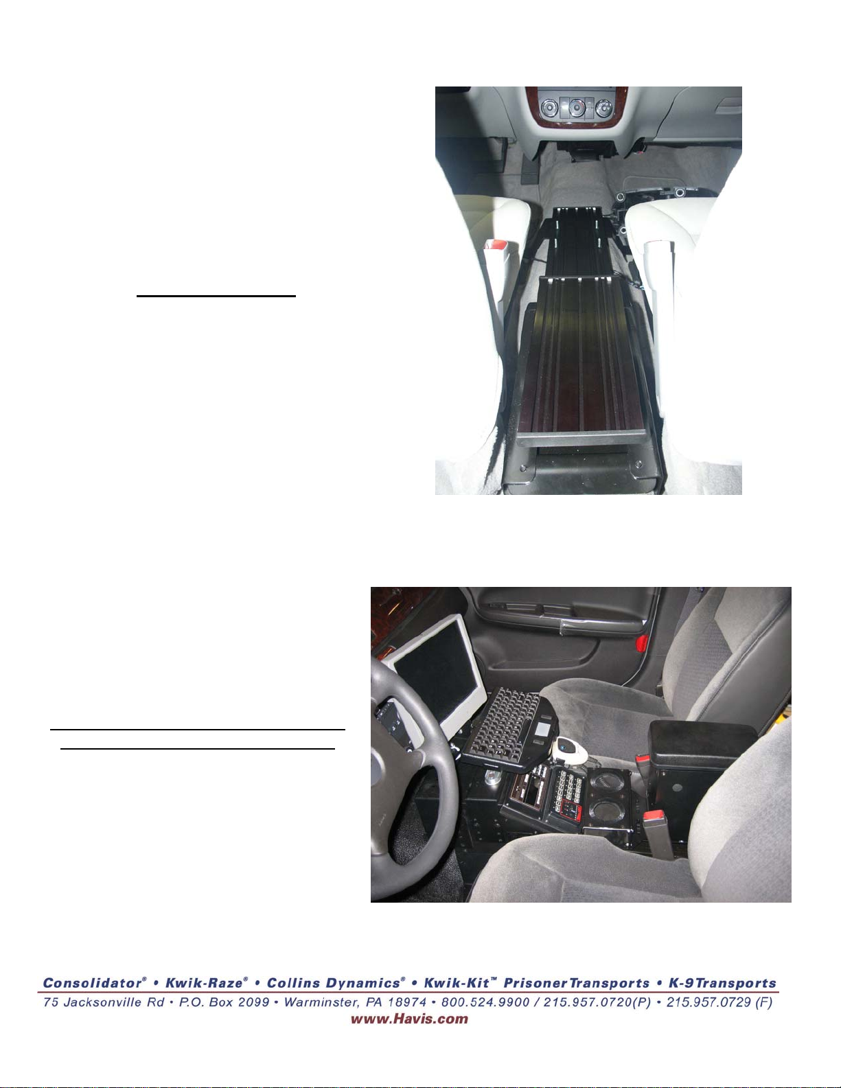
C-TM-IMP-1 installed
C-TM-IMP-1 installed w/ console, computer
mounts and accessories. (Sold separately)
4
C-TM-IMP-1_INST_11-08
 Loading...