

Page 1
INSTALL INSTRUCTIONS C-TCB-17
TELESCOPING COMPUTER BASE
1997-2003 FORD F-150 PICK-UP
2004 FORD F-150 (HERITAGE ONLY)
PICK-UP
NOTE: HERITAGE IS 2003 BODY STYLE CARRIED OVER TO 2004. FOR 2004
FORD F-150 NEW BODY STYLE USE C-TCB-31
TOOLS REQUIRED:
3/16” Allen wrench
3/8” Standard socket set
3/8” Metric socket set
HARDWARE & COMPONENTS:
QTY DESCRIPTION PART #
1 Pole support assembly CM93071-17
1 Telescoping pole assembly w/ 4” offset CM93072-3
1 ¼ x 1” Hex head lag bolt GSM33060
Ratcheting wrench (3/8” drive)
Powered drill w/ 3/16” drill bit
Open-end wrench set
Always
Read all instructions before installing any Havis-Shields Equipment Corp products.
Check for obstructions (Wire, brake lines, fuel tank, etc.) before drilling any holes!
Use hardware provided with install kit
!
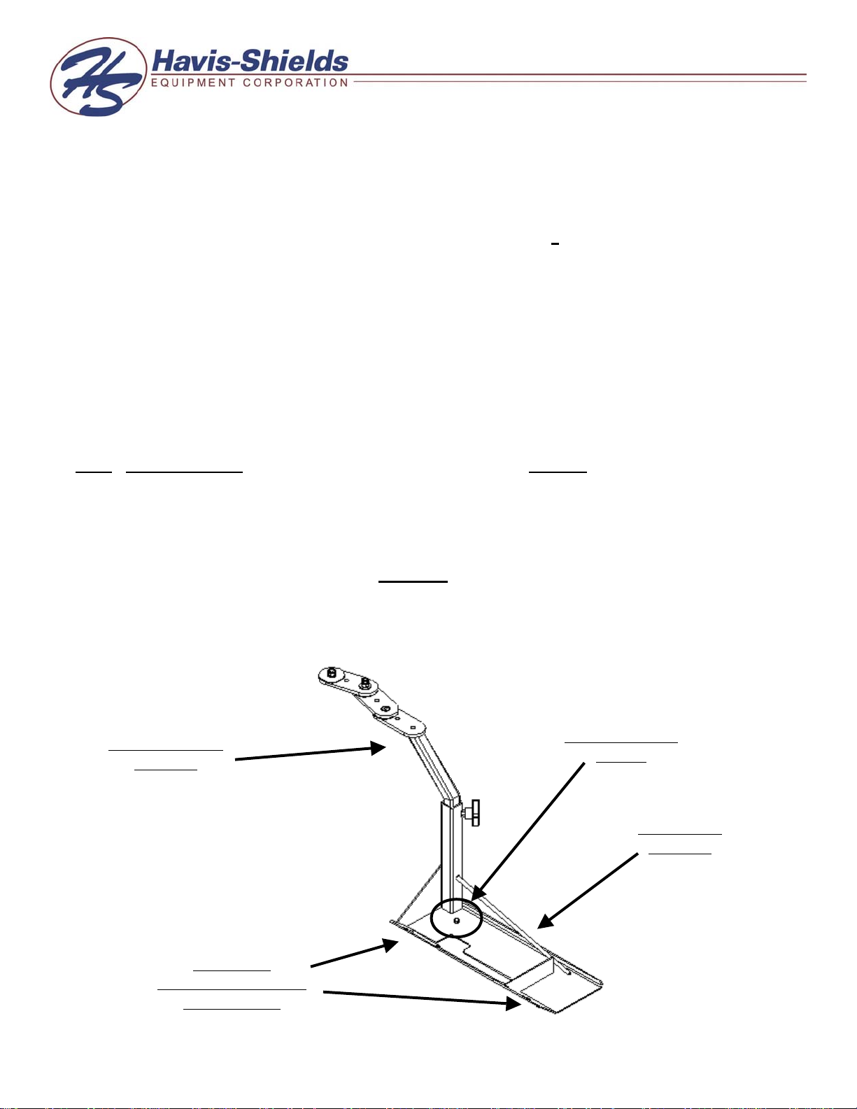
Telescoping pole
assembly
Location of
passenger side factory
seat base bolts
¼ x 1” Hex head
lag bolt
Pole support
assembly
C-TCB-17-INST-12-04
Page 2

SUB ASSEMBLY:
1. Confirm receipt of all hardware and components.
2. Remove front inner and outer passenger seat bolts on vehicle.
INSTALLATION:
1. Mount C-TCB-17 into vehicle:
• Position pole support assembly between seat base mount and floor of vehicle
• Align holes in pole support assembly with holes in seat base.
• Loosely attached factory seat bolts that were removed during subassembly.
• Pre-drill floor of vehicle at the location of the hole on the pole support assembly
using a 3/16” drill bit.
• Attach to vehicle using ¼” x 1” Hex head lag bolt.
Note: When drilling into floor of vehicle, be sure to check for obstructions prior to drilling or lag
bolting to floor.
• Tighten down passenger side factory seat bolts.
• Mount optional C-3090, computer-mounting platform, to telescoping pole assembly
using hardware and instructions provided with C-3090.
C-TCB-17-INST-12-04
 Loading...