

Havis ICS-B-F01-101, ICS-B-F02-101, ICS-B-F01-102, ICS-B-F02-102, ICS-B-F03-101 Owner's Manual
...
Owner’s Manual
Havis Integrated Control System
for Ford Police Interceptor Sedan & Utility
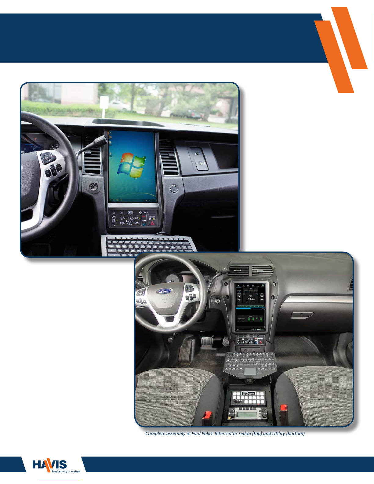
Complete assembly in Ford Police Interceptor Sedan (top) and Utility (bottom).
Keyboard and Console sold separately.
www.havis.com
1-800-458-3410
Havis Integrated Control System
Owner’s Manual Revision Description Date
ICS-B-FXX-XXX-OMN_6-25-14 Initial Release 6-25-2014
ICS-B-FXX-XXX-OMN_7-10-14
ICS-B-FXX-XXX-OMN_8-15-14
ICS-B-FXX-XXX-OMN_9-15-14
ICS-B-FXX-XXX-OMN_1-30-15
ICS-B-FXX-XXX-OMN_5-28-15
ICS-B-FXX-XXX-OMN_8-19-15
Troubleshooting updates, Part Number Matrix update,
and general information updates throughout manual
Troubleshooting and general information updates
throughout manual
Troubleshooting and general information updates
throughout manual
Troubleshooting and general information updates
throughout manual
Troubleshooting and general information updates
throughout manual
Model Year 2016 Updates
7-10-2014
8-15-2014
9-15-2014
1-30-2015
5-28-2015
8-19-2015
www.havis.com
1-800-458-3410
ICS-B-FXX-XXX-OMN_7-29-16
ICS-B-FXX-XXX-OMN_11-09-17
This Owner’s Manual applies to the following Part Numbers:
Model Year 2017 Updates
Model Year 2018 Updates
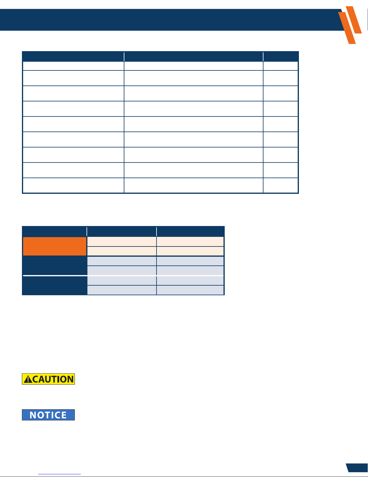
Vehicle Type Havis Part Number SYNC
Sedan (2013-2018)
ICS-B-F01-101
ICS-B-F01-102
ICS-B-F02-101
Utility (2013-2015)
ICS-B-F02-102
ICS-B-F03-101
Utility (2016-2018)
ICS-B-F03-102
The OEM radio and optional SYNC are replaced by the ICS.
The ICS cabling conguration is determined by whether or not the vehicle is equipped
with SYNC.
No
Yes
No
Yes
No
Yes
7-29-2016
11-09-2017
For technical support, please contact Havis at 1-800-458-3410 or visit www.havis.com for additional product support
and information.
• READ ALL INSTRUCTIONS THOROUGHLY BEFORE BEGINNING INSTALLATION.
• DO NOT OPERATE SYSTEM WHILE DRIVING YOUR VEHICLE.
• AFTER READING THE SYSTEM OVERVIEW SECTION OF THIS MANUAL (BEGINNING ON PAGE 9),
DOWNLOAD THE MOST CURRENT SOFTWARE TO ENSURE SYSTEM OPTIONS ARE UP-TO-DATE.
2

Table of Contents
www.havis.com
1-800-458-3410
Overview .........................................................................................
How the Integrated Control System works ........................................................
Video Integration ..........................................................................................
Audio Integration ..........................................................................................
Touch Screen Display Interface ......................................................................
HVAC Controls ...............................................................................................
ICS Modes of Operation ......................................................................
Power Modes .....................................................................................................
Conguration and Setup .....................................................................
Overview ............................................................................................................
Settings Application ...........................................................................................
Logging In or Out as Administrator .................................................................
Changing the Administrator Password ...........................................................
Settings Application – Administrator Operations - Access Control ............
Settings Application – Administrator Operations - File Export ..................
Settings Application – Administrator Operations - Personal Data .............
Settings Application – Administrator Operations - Device ........................
Apps ...................................................................................................
Audio Input Gains ........................................................................
Audio Output Gains .....................................................................
Discrete Outputs ..........................................................................
Control Mappings ........................................................................
System I/O ....................................................................................
Voltage Conguration ..................................................................
ICS Conguration .........................................................................
App Conguration ........................................................................
PC Audio/Video Conguration ......................................................
PC Audio Interface ........................................................................
Stay On After Ignition Off .............................................................
Software Update ..........................................................................
Software Update via Attached Laptop, Computer or Tablet ..........
Sound .............................................................................................................
Language & Input ...........................................................................................
Date & Time Setting .......................................................................................
About Device (for diagnostics and troubleshooting) ........................................
AM/FM/WB Radio Application .......................................................................
AUX Input Application ....................................................................................
NTSC Camera Application ...............................................................................
Backup Camera Application ............................................................................
AUX Camera Application .................................................................................
Clock Application ............................................................................................
Phone Application ...........................................................................................
System Application .........................................................................................
Image Viewer ..................................................................................................
Congure Computer, Laptop, or Tablet ...........................................................
4
4
4
4
5
6
8
8
9
9
9
9
10
10
11
11
12
12
12
12
13
13
15
15
16
18
18
19
20
21
22
23
23
23
23
24
24
25
25
25
26
26
29
30
31
Component Specications ...................................................................
Touch Screen Display ...............................................................................………….
HVAC Controls .........................................................................................………….
Embedded Processor ...............................................................................………….
A/V Extender ..........................................................................................………….
ICS Integration Overview .....................................................................
Wiring Diagram .......................................................................................………….
Troubleshooting .................................................................................
38
38
38
39
40
41
41
42
3
Overview
www.havis.com
1-800-458-3410
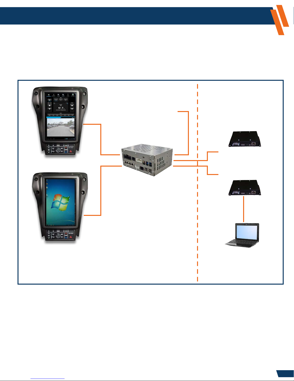
How the Integrated Control System Works
Video Integration
The ICS supports video inputs from a computer, camera, or digital video recorder (DVR). Video Display 1
mode is dedicated to display the ICS applications in the upper and lower portion of the screen. The
camera and/or DVR can be displayed in Video Display 1. Video Display 2 mode acts as a secondary
monitor of high-resolution video from a computer, laptop, or tablet in portrait orientation.
Vehicle Cabin Vehicle Trunk
The A/V Extender 2 allows
Camera
(VIDEO DISPLAY 1)
remote connectivity of
an externally connected
digital video recorder (DVR).
A/V Extender 2 (AVX2)
(optional)
A/V Extender 1 (AVX1)
VGA or HDMI
The Embedded Processor
connects to Ford wiring and
(VIDEO DISPLAY 2)
The Touch Screen Display
provides user control of all
functions and settings in the
Integrated Control System.
replaces the OEM AM/FM
Radio Module. A sophisticated
audio management system
prioritizes the use of the vehicle’s
audio system so important
communications are not missed.
The A/V Extender 1 allows
remote connectivity of
an externally connected
computer, laptop, or tablet.
Audio Integration
The ICS will help simplify your vehicle speakers and audio devices. The four vehicle speakers
will share audio inputs from your computer’s audio via the A/V Extender1 , DVR audio via the
A/V Extender 2 (optional), as well as inputs from the AM/FM Radio and, in systems with SYNC,
the 3.5mm AUX audio jack in the dash.
4

Overview (continued)
www.havis.com
1-800-458-3410
Touch Screen Display Interface
When viewing Video Display 1, the ICS Applications are split into top and bottom application
sections. The top section supports a tab selection of multiple applications. The bottom section
provides a single “always present” application. The system administrator can congure which
applications are available in the top and bottom sections.
The diagram below shows the basic screen layout:
Tab Selection for
Top Application
Top Application
Top/Bottom Application
Indicator Tabs
Bottom Application
Back Button
NOTE: This back function is used within some applications to back out of menus or dismiss
popups. Since there is only one back button, it will operate either the top or bottom application.
The Top/Bottom Application Indicator Tabs identify which application currently has “focus”
by highlighting a blue tab up or down. When you interact with apps via the touch screen, the
focus highlight automatically follows. The back button will always be sent to the highlighted
(last used) application.
Status and
Notication bar
5
Overview (continued)
www.havis.com
1-800-458-3410
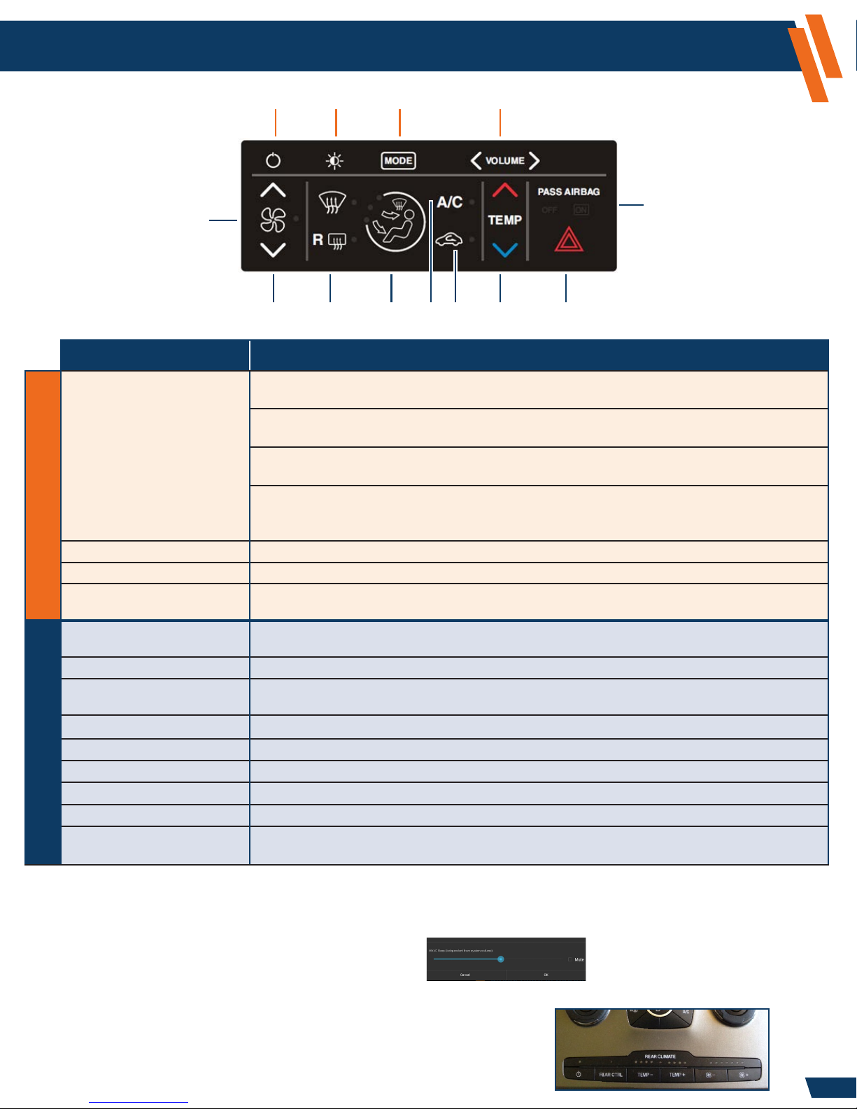
HVAC Controls
A
B
C
D
M
E
F J
G K
H L
I
Button Description
A. POWER Momentary press of the button: Enter a “Lights Out” state where the Touch Screen Display
lighting and USB keyboard power are disabled.
Second momentary press of the button: Turns the display and keyboard back on again. The
system remains Fully Operational from an audio perspective while in the “Lights Out” state.
Long press of the button (2-3 seconds, maximum): Initiates a reset request (warm boot).
A “Reset” window will appear. Select OK to reset, or Cancel to stop the operation.
Longer press of the button (minimum of 6 seconds): Use only if the ICS becomes
unresponsive. A continuous hold of the Power button for 6 seconds will force an immediate
hard reset (cold boot) of the system without any further conrmation by the user.
B. ILLUMINATION INTENSITY Select between 7 illumination levels with the press of this button.
C. MODE Alternate between Video Display 1 and Video Display 2 with a single touch of this button.
D. VOLUME Controls volume to the speakers.
Touch Screen Display ControlsHVAC Controls
E. HVAC ON/OFF Press to turn climate control on and off.
F. FAN SPEED Press Up or Down Arrow to control the volume of air circulated in your vehicle.
G. FRONT/REAR DEFROST Press to defog and clear windshield or rear window.
H. AIR DISTRIBUTION Select to distribute air through windshield vents, instrument panel vents, or oor vents.
I. A/C Press to turn on the Air Conditioning.
J. RECIRCULATE Press to switch from outside air to in-vehicle recirculated air.
K. TEMPERATURE Press Up or Down Arrow to control the temperature of the air being circulated in your vehicle.
L. HAZARD Press to ash all front and rear direction signals.
M. AIRBAG INDICATOR Indicator lights to inform vehicle occupants that the front passenger airbag is
(NOTE: On-board computer volume should be set to normalize the volume level with the AM/FM level)
(NOTE: HVAC must be ON for various controls to work. HVAC ON is indicated by the LED to the right of the FAN ICON)
(NOTE: Rear Defrost is only operational when engine is running)
either engaged or disabled (ON = engaged, OFF = disabled).
Backlight Intensity follows Instrument Panel Intensity control.
To adjust the volume level of the audible beep heard during a valid HVAC button press, perform the following steps:
1. Select the Settings icon from the “Tab Selection” area at the top of the screen.
2. Select Sound.
3. Select Mixer.
4. Adjust the slide next to ‘HVAC Beep’. Select OK.
NOTE: You will only have the ability to control rear vents if the vehicle
was equipped with the option to control rear vents (see image).
If vehicle was equipped with this option, settings for the
front vents are mirrored to the rear vents by default.
6
Overview (continued)
www.havis.com
1-800-458-3410
HVAC Controls (continued)
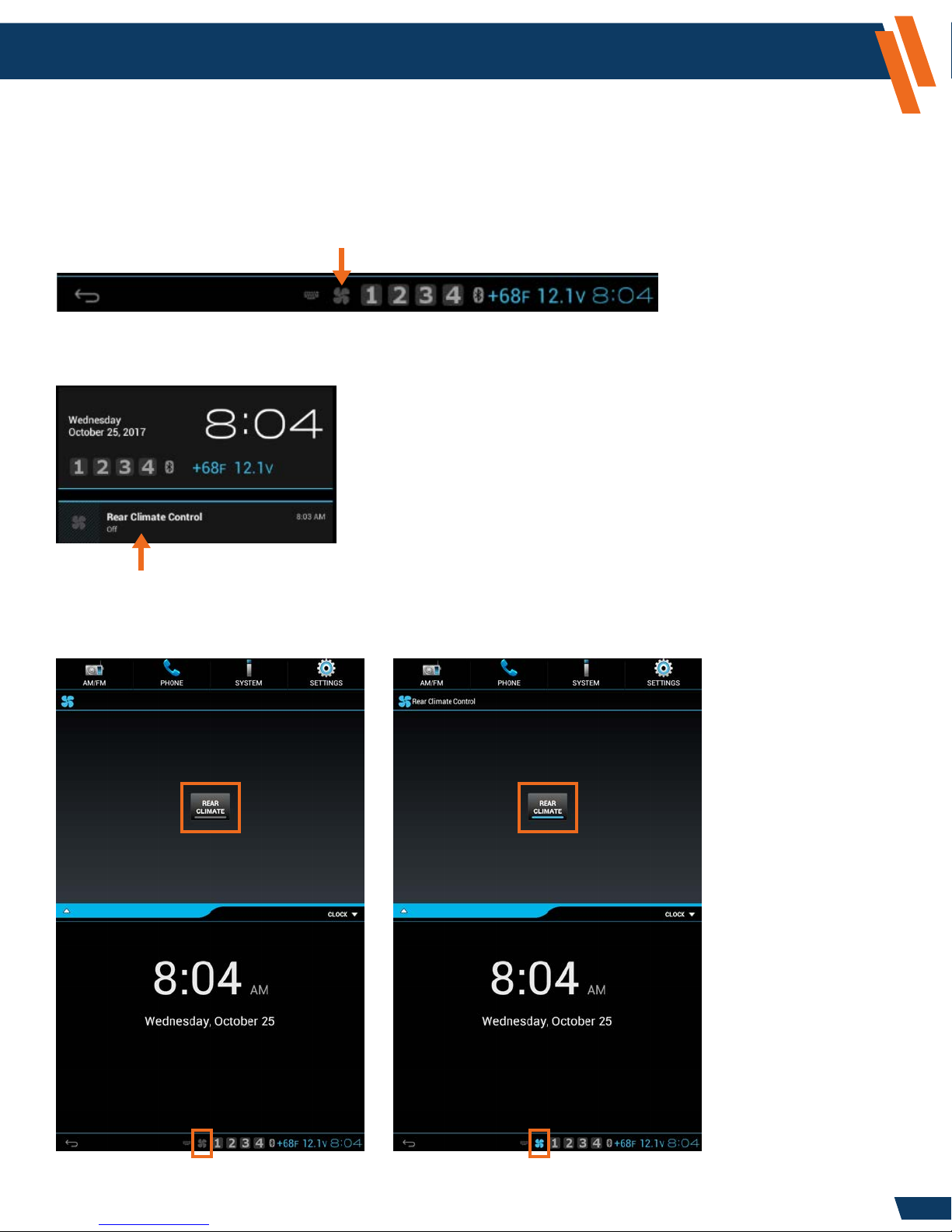
For Model Year 2016 and later SUVs equipped with the Rear Climate Control, the Rear HVAC vents
can be disabled. This is useful for vehicles equipped with dog cages in conditions where you may
want heat blowing in the front cabin but not on the dogs in the back.
If the vehicle is equipped with Rear Climate control, a fan icon will appear at the bottom of
the ICS display (Blue=On, Gray=Off).
Press the fan icon to open the notication window. Select the Rear Climate Control notication
to access the application.
Press the Rear Climate control button to toggle the rear climate on/off.
When the rear climate is on, it will mirror the front climate control settings.
Rear Climate is shown as OFF Rear Climate is shown as ON
7

ICS Modes of Operation
www.havis.com
1-800-458-3410
Power Modes
Dark Mode:
• When in Dark Mode, the ICS is at its lowest power state (combined battery load for all ICS
components is less than 1 mA).
• Keyboard backlighting will turn off in Dark Mode. When you bring the screen back up, you must
push the button on the keyboard to turn the backlighting on again.
• The ICS will transition from Dark Mode to Fully Operational when the vehicle key is turned to
ACC or RUN positions. The transition from Dark Mode to Fully Operational takes less than a minute.
• If the vehicle key is rotated to the START position, the ICS will mute the audio amplier and turn
off the LCD for the duration of the engine crank.
Fully Operational:
• The ICS remains in Fully Operational mode while the vehicle key is at ACC or RUN.
Standby:
• When the vehicle key is turned to OFF and the driver side door is opened, the ICS enters
a 48-hour Standby state where the operating system state is retained by the battery.
• During this 48-hour period, the system consumes more power than Dark Mode
(approximately 30mA versus 1mA), but is able to wake up to Fully Operational within 3 seconds.
• After 48 hours of Standby, the ICS will transition to Dark Mode to minimize power consumption,
and the next start up will require more time to boot.
8
Configuration and Setup
Overview
The Embedded Processor comes with the following standard software applications:
Application Function
AM/FM/WB Radio Tuning and controls for the AM/FM/WB radio
AUX Input Control of the auxiliary audio input (mute or listen)
NTSC Camera View the NTSC composite camera input
Backup Camera The NTSC composite camera image will appear when in Reverse gear
System Health and status indicators for system components
Image Viewer Display a static image (used as optional screen ller)
Settings Conguration of system options
Clock Display Date and Time in application window
AVX Camera* View the secondary AVX digital video input
Phone* Allows Bluetooth Phone integration
* AVX Camera and Phone require additional equipment that can be purchased from Havis.
Settings Application
www.havis.com
1-800-458-3410
The Settings application allows the user to congure options for the ICS system.
Administrator operations (setup)
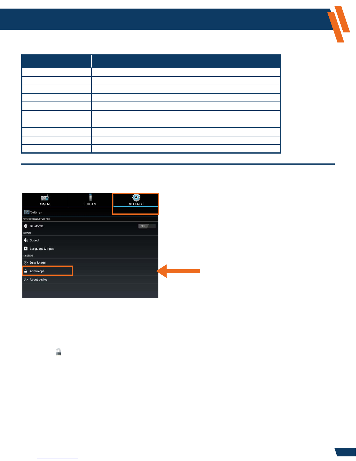
Logging in or out as Administrator
The “Admin Ops” section is password protected to prevent unauthorized access to the
system congurations settings.
To change System Settings perform the following steps:
1. Select the Settings icon from the “Tab Selection” area at the top of the screen.
2. Select Admin Ops.
3. Select Access Control.
4. Select Log in.
5. A “Login Required” window will appear. When asked for the Administrator password enter
the following:
a. Password: 0000 (Four Zeros)
NOTE: This is the System Default Password, to Change Password see Page 10.
b. Select Log in.
You are now logged in as Administrator. To log out of Administrator, perform the steps above;
however at Step 4, select Log out.
To conrm you are logged in as the Administrator, select the Notication area at the lower
right-hand corner of the screen. You will see “Access Control – Currently logged in as Administrator”.
9
Configuration and Setup (continued)
Changing the Administrator Password
1. Select the Settings icon from the “Tab Selection” area at the top of the screen.
2. Select Admin Ops.
3. Select Access Control.
4. Select Change Password.
5. Enter current password into Password eld.
6. Enter in a new password into New Password and Conrm Password elds.
7. Select OK.
Your password is now changed.
www.havis.com
1-800-458-3410
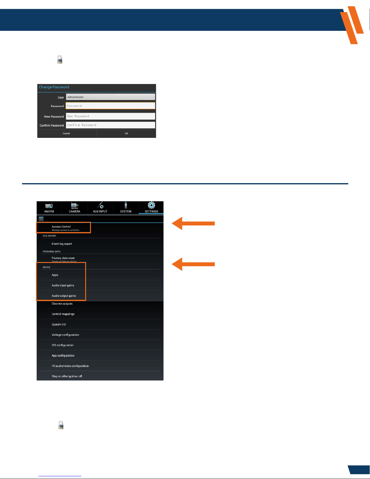
Settings Application - Administrator Operations - Access Control
Setup Administrator Protection
and Password
Device conguration
(touch and swipe upward
to scroll for more options)
Enable User Account Control (checkbox)
The ICS has the ability to limit the user’s access to modify system settings. By default the
system is locked. To limit the user’s access system settings, perform the following steps:
1. Select the Settings icon from the “Tab Selection” area at the top of the screen.
2. Select Admin Ops.
3. Select Access Control.
4. Select Enable user access control.
If the box is checked (default state), the user will need to enter the administrative password
to change settings. If the box is unchecked, then all operations are available without the
administrative password.
10
Configuration and Setup (continued)
www.havis.com
1-800-458-3410
Settings Application - Administrator Operations - File Export
Event Log Export
This setting allows you to send diagnostic data back to Havis. In the event of a system issue, please
contact Havis Technical Support at 1-800-458-3410. If Havis requests an Event Log Export to
assist with the support of your system, perform the following steps:
1. Insert a USB Memory Stick into the USB port found on the dash.
2. Select the Settings icon from the “Tab Selection” area at the top of the screen.
3. Select Admin Ops.
4. Select Event Log Export.
5. An “Event Log Export” window will appear, press OK to begin the export process, or
press Cancel to stop the process.
6. The system will conrm when the export was successful. Select OK to complete the process.
On the USB Memory Stick, you will nd the Event Log Export process has created an “Exports”
folder containing a sub-folder named similar to “2015_01_01_at_08_05_30”. The entire
sub-folder should be sent to Havis Technical Support for evaluation.
Settings Application - Administrator Operations - Personal Data
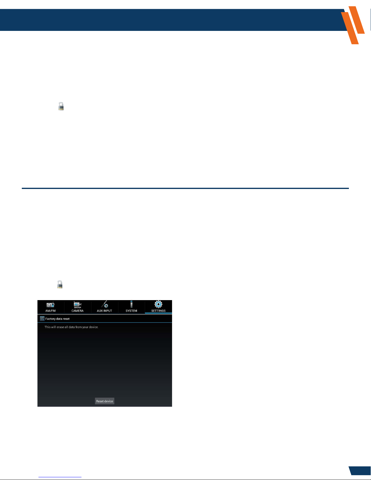
Factory data reset
This setting allows you to restore all system settings to the factory defaults. This will overwrite
any existing preferences and user adjustments. This should not be done without specic direction
from the Havis Technical Support Team.
To perform a Factory data reset perform the following steps:
1. Backup all system settings prior to performing this step.
(refer to ICS Conguration > Export, Page 16, for directions)
2. Select the Settings icon from the “Tab Selection” area at the top of the screen.
3. Select Admin Ops.
4. Select Factory data reset.
5. Select the Reset device button.
6. A window will appear stating, “Erase all data? You can’t reverse this action.”
7. Select Erase Everything.
This process may take several minutes to complete.
11
Configuration and Setup (continued)
Settings Application - Administrator Operations - Device
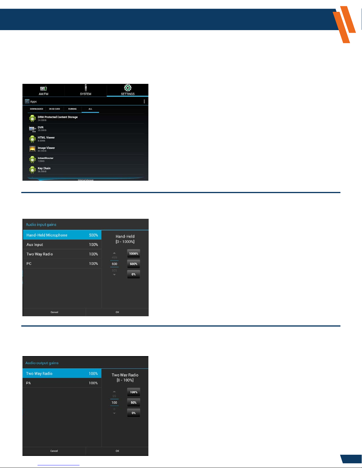
Apps
This setting provides a standard Android view of the running applications and processors.
This section is normally only used for diagnostic purposes and should not be used without
direction from the Havis Technical Support Team.
www.havis.com
1-800-458-3410
Audio Input Gains
This setting allows the system administrator to adjust the relative volume levels for the various inputs.
NOTE: Hand-Held Microphone and Two Way Radio (optional)
Audio Output Gains
This setting allows the system administrator to adjust the audio output volume levels.
NOTE: Two Way Radio and PA (optional)
12
Configuration and Setup (continued)
www.havis.com
1-800-458-3410
Settings Application - Administrator Operations - Device (continued)
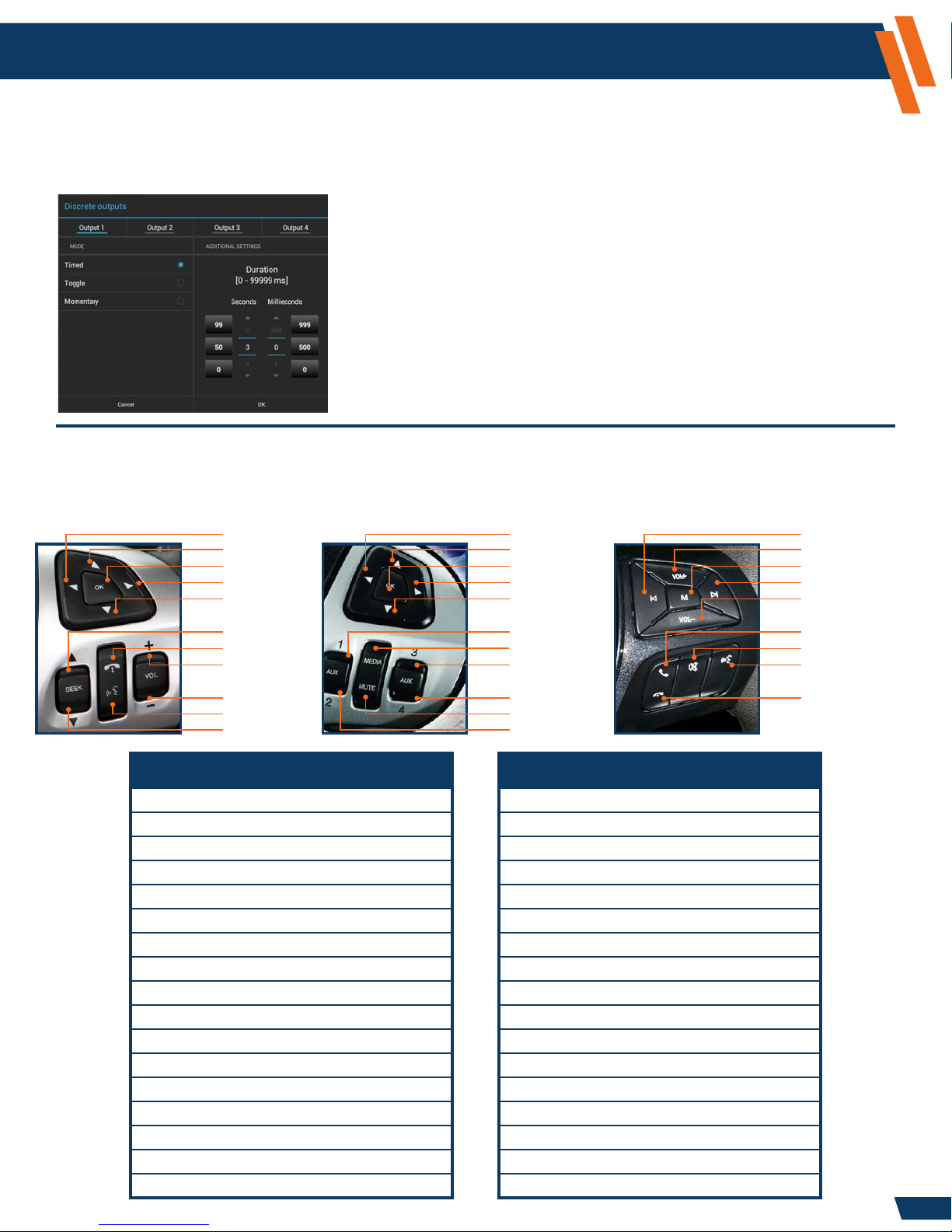
Discrete Outputs
This setting allows the system administrator to select the behavior of each discrete output (timed, toggle,
or momentary).
NOTE: Discrete outputs (optional)
Control Mappings
The ICS provides exible control options for vehicle functions. The control logic can map steering
wheel to output functions. The Ford steering wheel controls are supported as part of this logic.
Standard Ford Steering Wheel controls.
5-Way Left
5-Way Up
5-Way OK
5-Way Right
5-Way Down
Special Ford Steering Wheel controls.
5-Way Left
5-Way Up
5-Way OK
5-Way Right
5-Way Down
Model Year 2016-17 Utility Steering Wheel controls.
Seek Down
Volume Up
Media
Seek Up
Volume Down
Seek Up
Phone
Volume Up
Volume Down
PTT
Seek Down
Available Input Controls Available Output Functions
5-Way Down AM/FM Radio Band AM
5-Way Left AM/FM Radio Band FM
5-Way Ok AM/FM Radio Band WB
5-Way Right AM/FM Radio Preset Down
5-Way Up AM/FM Radio Preset Up
Media AM/FM Radio Seek Down
Mute AM/FM Radio Seek Up
PPT AM/FM Radio Tune Down
Phone AM/FM Radio Tune Up
Phone Down Entertainment Audio Mute Toggle
Phone Up Hands Free Mic
Seek Down System Brightness
Seek Up System Mode
Volume Down System Volume Down
Volume Up System Volume Up
Output Relay 1-4* Output Relay 1-4*
Not Supported
Media
Not Supported
Not Supported
Mute
Not Supported
Phone Voice Toggle
* Output Relay 1-4 (optional)* Output Relay 1-4 (optional)
Phone
Mute
Not Supported
Not Supported
13
Configuration and Setup (continued)
www.havis.com
1-800-458-3410
Settings Application - Administrator Operations - Device (continued)
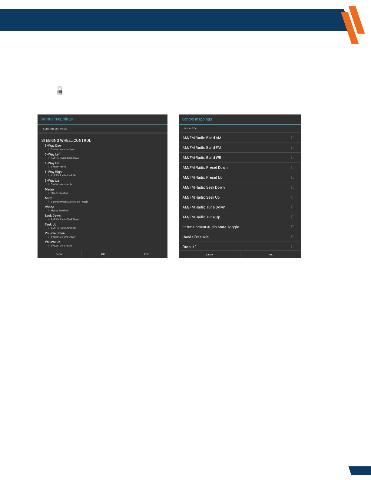
Control Mappings (continued)
This setting allows you to congure desired functions for the steering wheel controls.
To view the current control mappings perform the following steps:
1. Select the Settings icon from the “Tab Selection” area at the top of the screen.
2. Select Admin Ops.
3. Select Control Mappings.
4. A “Control Mappings” window will appear with a summary of the current mappings.
To edit the current mappings, perform the following steps:
1. Select the Edit button as seen above.
2. Select the item that you wish to edit, for example: 5-Way Left.
3. A window will appear; all active items will have a check mark located within the box to the
right of the control.
4. Scroll to select your desired control.
5. Select your desired row, and the check mark will appear when the action has been assigned.
6. Select OK.
7. Select the next item you wish to edit, if desired. If complete, select OK.
8. The System will show you the updated Control Mappings Summary. If you are done with
modifying your settings, select OK. If not, go back up to step 1 and repeat as necessary.
9. A window will appear stating “Control Mappings - Updating settings, this will take a few seconds.”
14
Configuration and Setup (continued)
www.havis.com
1-800-458-3410
Settings Application - Administrator Operations - Device (continued)
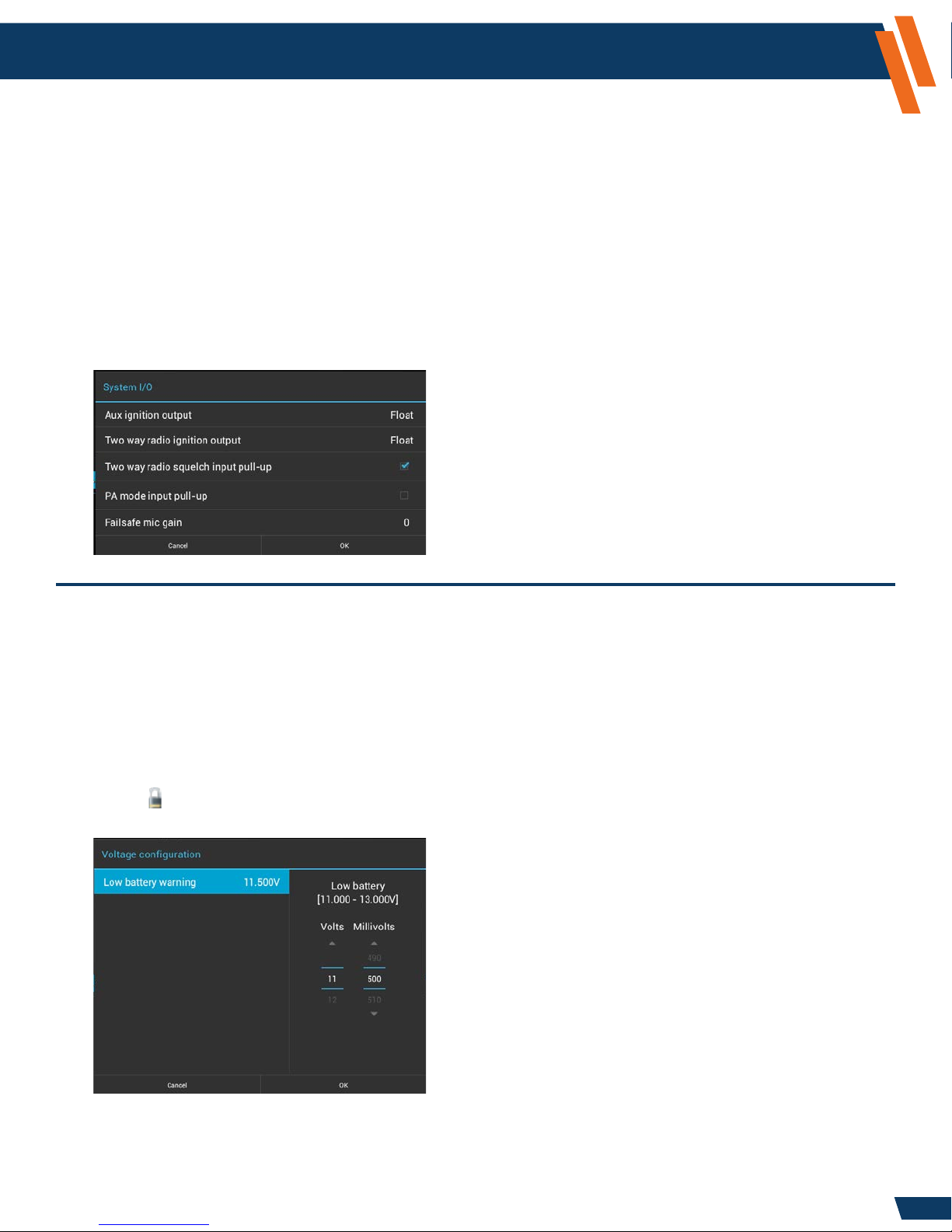
System I/O
This setting allows you to congure hardware characteristics for some of the device control pins.
The correct settings depend on the specic system implementation. Please contact Havis Technical
Support prior to changing any of these settings.
1. Select the Settings icon from the “Tab Selection” area at the top of the screen.
2. Select Admin Ops.
3. Select System I/O.
4. Select Two way radio squelch input pull-up if you do not have the two way radio option for the ICS.
This setting allows the AM/FM/WB Radio to utilize the in-vehicle speaker system.
NOTE: Contact Havis Technical Support prior to adjusting any other settings.
If you do not have the two way radio
option for the ICS, then you will need
to select the Two way radio squelch
input pull-up, so a check mark is
placed in the box. This will enable
audio on the ICS.
Voltage Conguration
This setting allows you to modify the default setting for the vehicle’s battery voltage, which is
displayed at all times in the lower right-hand corner of the Touch Screen Display. If your vehicle
is operating above the Low Battery Warning level; the voltage will be displayed in Blue text. If your
vehicle is operating below the Low Battery Warning, the voltage will appear in red, and a system
notication will appear. By default the Low Battery Warning is set at 11.500V. If you desire to
change the Voltage Conguration default setting, perform the following steps:
1. Select the Settings icon from the “Tab Selection” area at the top of the screen.
2. Select Admin Ops.
3. Select Voltage conguration.
4. Adjust the Volt and Millivolts to your desired setting (11.000 - 13.000V) by using the Up or Down
icons or by swiping your nger over the Volts or Millivolts numbers.
5. Select OK.
The ICS has an automatic shutdown procedure, which is xed at 10.5V.
15
 Loading...