

Havis ICS-B-F01-101, ICS-B-F02-101, ICS-B-F01-102, ICS-B-F02-102, ICS-B-F03-101 Owner's Manual
...Page 1
Owner’s Manual
Havis Integrated Control System
for Ford Police Interceptor Sedan & Utility
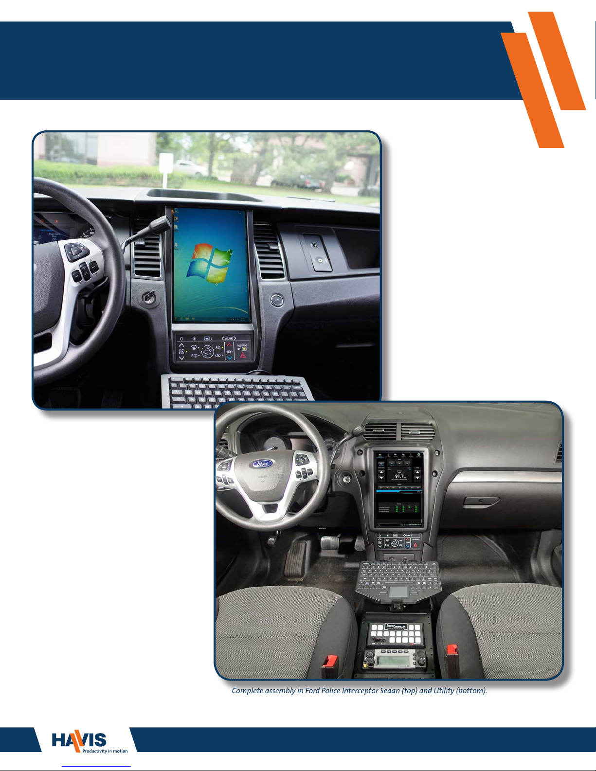
Complete assembly in Ford Police Interceptor Sedan (top) and Utility (bottom).
Keyboard and Console sold separately.
www.havis.com
1-800-458-3410
Page 2
Havis Integrated Control System
Owner’s Manual Revision Description Date
ICS-B-FXX-XXX-OMN_6-25-14 Initial Release 6-25-2014
ICS-B-FXX-XXX-OMN_7-10-14
ICS-B-FXX-XXX-OMN_8-15-14
ICS-B-FXX-XXX-OMN_9-15-14
ICS-B-FXX-XXX-OMN_1-30-15
ICS-B-FXX-XXX-OMN_5-28-15
ICS-B-FXX-XXX-OMN_8-19-15
Troubleshooting updates, Part Number Matrix update,
and general information updates throughout manual
Troubleshooting and general information updates
throughout manual
Troubleshooting and general information updates
throughout manual
Troubleshooting and general information updates
throughout manual
Troubleshooting and general information updates
throughout manual
Model Year 2016 Updates
7-10-2014
8-15-2014
9-15-2014
1-30-2015
5-28-2015
8-19-2015
www.havis.com
1-800-458-3410
ICS-B-FXX-XXX-OMN_7-29-16
ICS-B-FXX-XXX-OMN_11-09-17
This Owner’s Manual applies to the following Part Numbers:
Model Year 2017 Updates
Model Year 2018 Updates
Vehicle Type Havis Part Number SYNC
Sedan (2013-2018)
ICS-B-F01-101
ICS-B-F01-102
ICS-B-F02-101
Utility (2013-2015)
ICS-B-F02-102
ICS-B-F03-101
Utility (2016-2018)
ICS-B-F03-102
The OEM radio and optional SYNC are replaced by the ICS.
The ICS cabling conguration is determined by whether or not the vehicle is equipped
with SYNC.
No
Yes
No
Yes
No
Yes
7-29-2016
11-09-2017
For technical support, please contact Havis at 1-800-458-3410 or visit www.havis.com for additional product support
and information.
• READ ALL INSTRUCTIONS THOROUGHLY BEFORE BEGINNING INSTALLATION.
• DO NOT OPERATE SYSTEM WHILE DRIVING YOUR VEHICLE.
• AFTER READING THE SYSTEM OVERVIEW SECTION OF THIS MANUAL (BEGINNING ON PAGE 9),
DOWNLOAD THE MOST CURRENT SOFTWARE TO ENSURE SYSTEM OPTIONS ARE UP-TO-DATE.
2
Page 3

Table of Contents
www.havis.com
1-800-458-3410
Overview .........................................................................................
How the Integrated Control System works ........................................................
Video Integration ..........................................................................................
Audio Integration ..........................................................................................
Touch Screen Display Interface ......................................................................
HVAC Controls ...............................................................................................
ICS Modes of Operation ......................................................................
Power Modes .....................................................................................................
Conguration and Setup .....................................................................
Overview ............................................................................................................
Settings Application ...........................................................................................
Logging In or Out as Administrator .................................................................
Changing the Administrator Password ...........................................................
Settings Application – Administrator Operations - Access Control ............
Settings Application – Administrator Operations - File Export ..................
Settings Application – Administrator Operations - Personal Data .............
Settings Application – Administrator Operations - Device ........................
Apps ...................................................................................................
Audio Input Gains ........................................................................
Audio Output Gains .....................................................................
Discrete Outputs ..........................................................................
Control Mappings ........................................................................
System I/O ....................................................................................
Voltage Conguration ..................................................................
ICS Conguration .........................................................................
App Conguration ........................................................................
PC Audio/Video Conguration ......................................................
PC Audio Interface ........................................................................
Stay On After Ignition Off .............................................................
Software Update ..........................................................................
Software Update via Attached Laptop, Computer or Tablet ..........
Sound .............................................................................................................
Language & Input ...........................................................................................
Date & Time Setting .......................................................................................
About Device (for diagnostics and troubleshooting) ........................................
AM/FM/WB Radio Application .......................................................................
AUX Input Application ....................................................................................
NTSC Camera Application ...............................................................................
Backup Camera Application ............................................................................
AUX Camera Application .................................................................................
Clock Application ............................................................................................
Phone Application ...........................................................................................
System Application .........................................................................................
Image Viewer ..................................................................................................
Congure Computer, Laptop, or Tablet ...........................................................
4
4
4
4
5
6
8
8
9
9
9
9
10
10
11
11
12
12
12
12
13
13
15
15
16
18
18
19
20
21
22
23
23
23
23
24
24
25
25
25
26
26
29
30
31
Component Specications ...................................................................
Touch Screen Display ...............................................................................………….
HVAC Controls .........................................................................................………….
Embedded Processor ...............................................................................………….
A/V Extender ..........................................................................................………….
ICS Integration Overview .....................................................................
Wiring Diagram .......................................................................................………….
Troubleshooting .................................................................................
38
38
38
39
40
41
41
42
3
Page 4
Overview
www.havis.com
1-800-458-3410
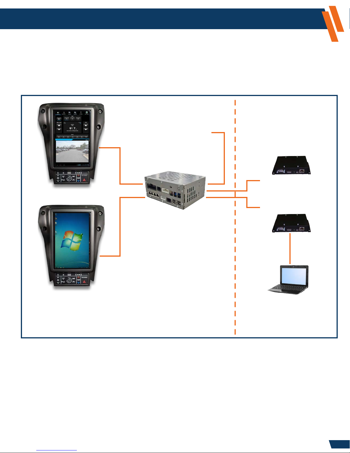
How the Integrated Control System Works
Video Integration
The ICS supports video inputs from a computer, camera, or digital video recorder (DVR). Video Display 1
mode is dedicated to display the ICS applications in the upper and lower portion of the screen. The
camera and/or DVR can be displayed in Video Display 1. Video Display 2 mode acts as a secondary
monitor of high-resolution video from a computer, laptop, or tablet in portrait orientation.
Vehicle Cabin Vehicle Trunk
The A/V Extender 2 allows
Camera
(VIDEO DISPLAY 1)
remote connectivity of
an externally connected
digital video recorder (DVR).
A/V Extender 2 (AVX2)
(optional)
A/V Extender 1 (AVX1)
VGA or HDMI
The Embedded Processor
connects to Ford wiring and
(VIDEO DISPLAY 2)
The Touch Screen Display
provides user control of all
functions and settings in the
Integrated Control System.
replaces the OEM AM/FM
Radio Module. A sophisticated
audio management system
prioritizes the use of the vehicle’s
audio system so important
communications are not missed.
The A/V Extender 1 allows
remote connectivity of
an externally connected
computer, laptop, or tablet.
Audio Integration
The ICS will help simplify your vehicle speakers and audio devices. The four vehicle speakers
will share audio inputs from your computer’s audio via the A/V Extender1 , DVR audio via the
A/V Extender 2 (optional), as well as inputs from the AM/FM Radio and, in systems with SYNC,
the 3.5mm AUX audio jack in the dash.
4
Page 5

Overview (continued)
www.havis.com
1-800-458-3410
Touch Screen Display Interface
When viewing Video Display 1, the ICS Applications are split into top and bottom application
sections. The top section supports a tab selection of multiple applications. The bottom section
provides a single “always present” application. The system administrator can congure which
applications are available in the top and bottom sections.
The diagram below shows the basic screen layout:
Tab Selection for
Top Application
Top Application
Top/Bottom Application
Indicator Tabs
Bottom Application
Back Button
NOTE: This back function is used within some applications to back out of menus or dismiss
popups. Since there is only one back button, it will operate either the top or bottom application.
The Top/Bottom Application Indicator Tabs identify which application currently has “focus”
by highlighting a blue tab up or down. When you interact with apps via the touch screen, the
focus highlight automatically follows. The back button will always be sent to the highlighted
(last used) application.
Status and
Notication bar
5
Page 6
Overview (continued)
www.havis.com
1-800-458-3410
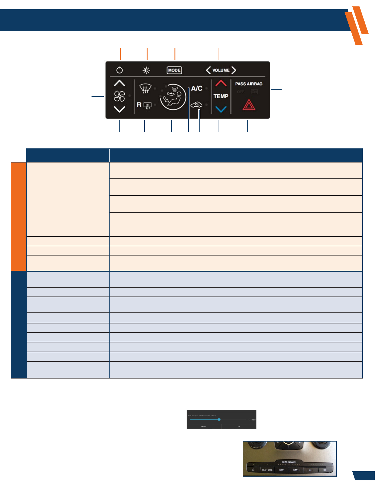
HVAC Controls
A
B
C
D
M
E
F J
G K
H L
I
Button Description
A. POWER Momentary press of the button: Enter a “Lights Out” state where the Touch Screen Display
lighting and USB keyboard power are disabled.
Second momentary press of the button: Turns the display and keyboard back on again. The
system remains Fully Operational from an audio perspective while in the “Lights Out” state.
Long press of the button (2-3 seconds, maximum): Initiates a reset request (warm boot).
A “Reset” window will appear. Select OK to reset, or Cancel to stop the operation.
Longer press of the button (minimum of 6 seconds): Use only if the ICS becomes
unresponsive. A continuous hold of the Power button for 6 seconds will force an immediate
hard reset (cold boot) of the system without any further conrmation by the user.
B. ILLUMINATION INTENSITY Select between 7 illumination levels with the press of this button.
C. MODE Alternate between Video Display 1 and Video Display 2 with a single touch of this button.
D. VOLUME Controls volume to the speakers.
Touch Screen Display ControlsHVAC Controls
E. HVAC ON/OFF Press to turn climate control on and off.
F. FAN SPEED Press Up or Down Arrow to control the volume of air circulated in your vehicle.
G. FRONT/REAR DEFROST Press to defog and clear windshield or rear window.
H. AIR DISTRIBUTION Select to distribute air through windshield vents, instrument panel vents, or oor vents.
I. A/C Press to turn on the Air Conditioning.
J. RECIRCULATE Press to switch from outside air to in-vehicle recirculated air.
K. TEMPERATURE Press Up or Down Arrow to control the temperature of the air being circulated in your vehicle.
L. HAZARD Press to ash all front and rear direction signals.
M. AIRBAG INDICATOR Indicator lights to inform vehicle occupants that the front passenger airbag is
(NOTE: On-board computer volume should be set to normalize the volume level with the AM/FM level)
(NOTE: HVAC must be ON for various controls to work. HVAC ON is indicated by the LED to the right of the FAN ICON)
(NOTE: Rear Defrost is only operational when engine is running)
either engaged or disabled (ON = engaged, OFF = disabled).
Backlight Intensity follows Instrument Panel Intensity control.
To adjust the volume level of the audible beep heard during a valid HVAC button press, perform the following steps:
1. Select the Settings icon from the “Tab Selection” area at the top of the screen.
2. Select Sound.
3. Select Mixer.
4. Adjust the slide next to ‘HVAC Beep’. Select OK.
NOTE: You will only have the ability to control rear vents if the vehicle
was equipped with the option to control rear vents (see image).
If vehicle was equipped with this option, settings for the
front vents are mirrored to the rear vents by default.
6
Page 7
Overview (continued)
www.havis.com
1-800-458-3410
HVAC Controls (continued)
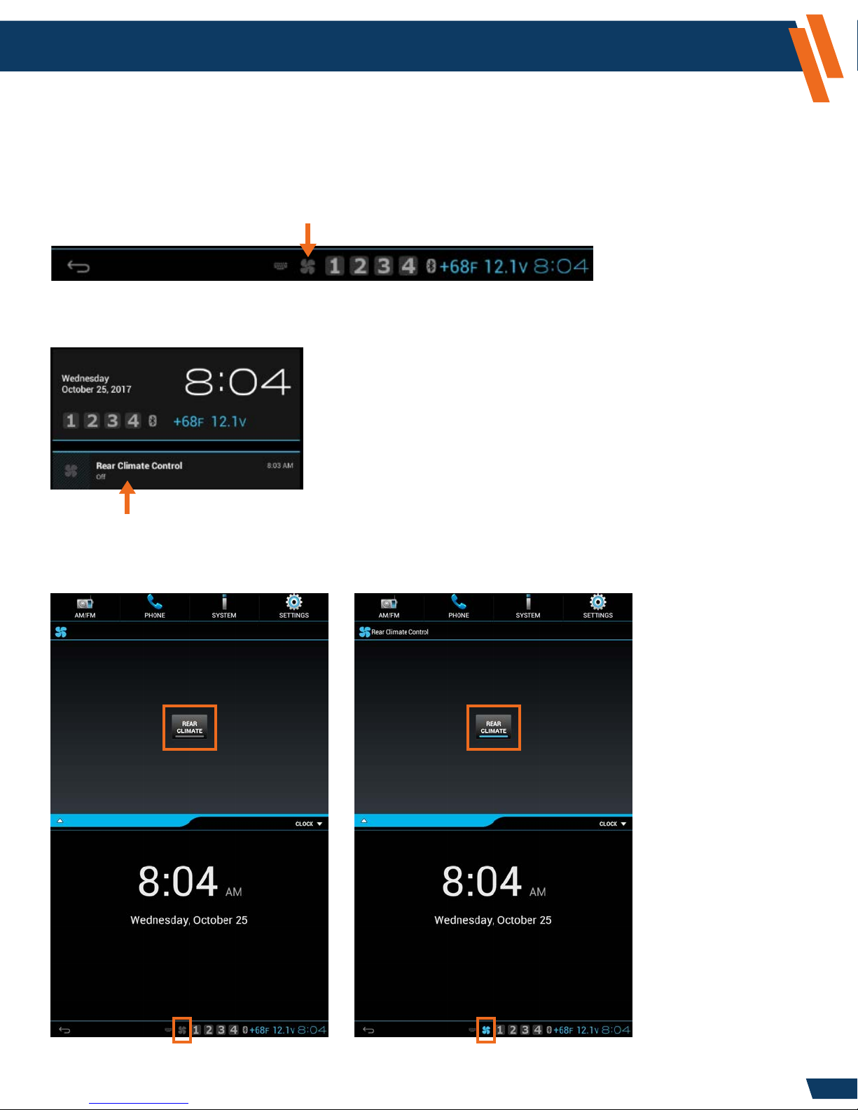
For Model Year 2016 and later SUVs equipped with the Rear Climate Control, the Rear HVAC vents
can be disabled. This is useful for vehicles equipped with dog cages in conditions where you may
want heat blowing in the front cabin but not on the dogs in the back.
If the vehicle is equipped with Rear Climate control, a fan icon will appear at the bottom of
the ICS display (Blue=On, Gray=Off).
Press the fan icon to open the notication window. Select the Rear Climate Control notication
to access the application.
Press the Rear Climate control button to toggle the rear climate on/off.
When the rear climate is on, it will mirror the front climate control settings.
Rear Climate is shown as OFF Rear Climate is shown as ON
7
Page 8

ICS Modes of Operation
www.havis.com
1-800-458-3410
Power Modes
Dark Mode:
• When in Dark Mode, the ICS is at its lowest power state (combined battery load for all ICS
components is less than 1 mA).
• Keyboard backlighting will turn off in Dark Mode. When you bring the screen back up, you must
push the button on the keyboard to turn the backlighting on again.
• The ICS will transition from Dark Mode to Fully Operational when the vehicle key is turned to
ACC or RUN positions. The transition from Dark Mode to Fully Operational takes less than a minute.
• If the vehicle key is rotated to the START position, the ICS will mute the audio amplier and turn
off the LCD for the duration of the engine crank.
Fully Operational:
• The ICS remains in Fully Operational mode while the vehicle key is at ACC or RUN.
Standby:
• When the vehicle key is turned to OFF and the driver side door is opened, the ICS enters
a 48-hour Standby state where the operating system state is retained by the battery.
• During this 48-hour period, the system consumes more power than Dark Mode
(approximately 30mA versus 1mA), but is able to wake up to Fully Operational within 3 seconds.
• After 48 hours of Standby, the ICS will transition to Dark Mode to minimize power consumption,
and the next start up will require more time to boot.
8
Page 9
Configuration and Setup
Overview
The Embedded Processor comes with the following standard software applications:
Application Function
AM/FM/WB Radio Tuning and controls for the AM/FM/WB radio
AUX Input Control of the auxiliary audio input (mute or listen)
NTSC Camera View the NTSC composite camera input
Backup Camera The NTSC composite camera image will appear when in Reverse gear
System Health and status indicators for system components
Image Viewer Display a static image (used as optional screen ller)
Settings Conguration of system options
Clock Display Date and Time in application window
AVX Camera* View the secondary AVX digital video input
Phone* Allows Bluetooth Phone integration
* AVX Camera and Phone require additional equipment that can be purchased from Havis.
Settings Application
www.havis.com
1-800-458-3410
The Settings application allows the user to congure options for the ICS system.
Administrator operations (setup)
Logging in or out as Administrator
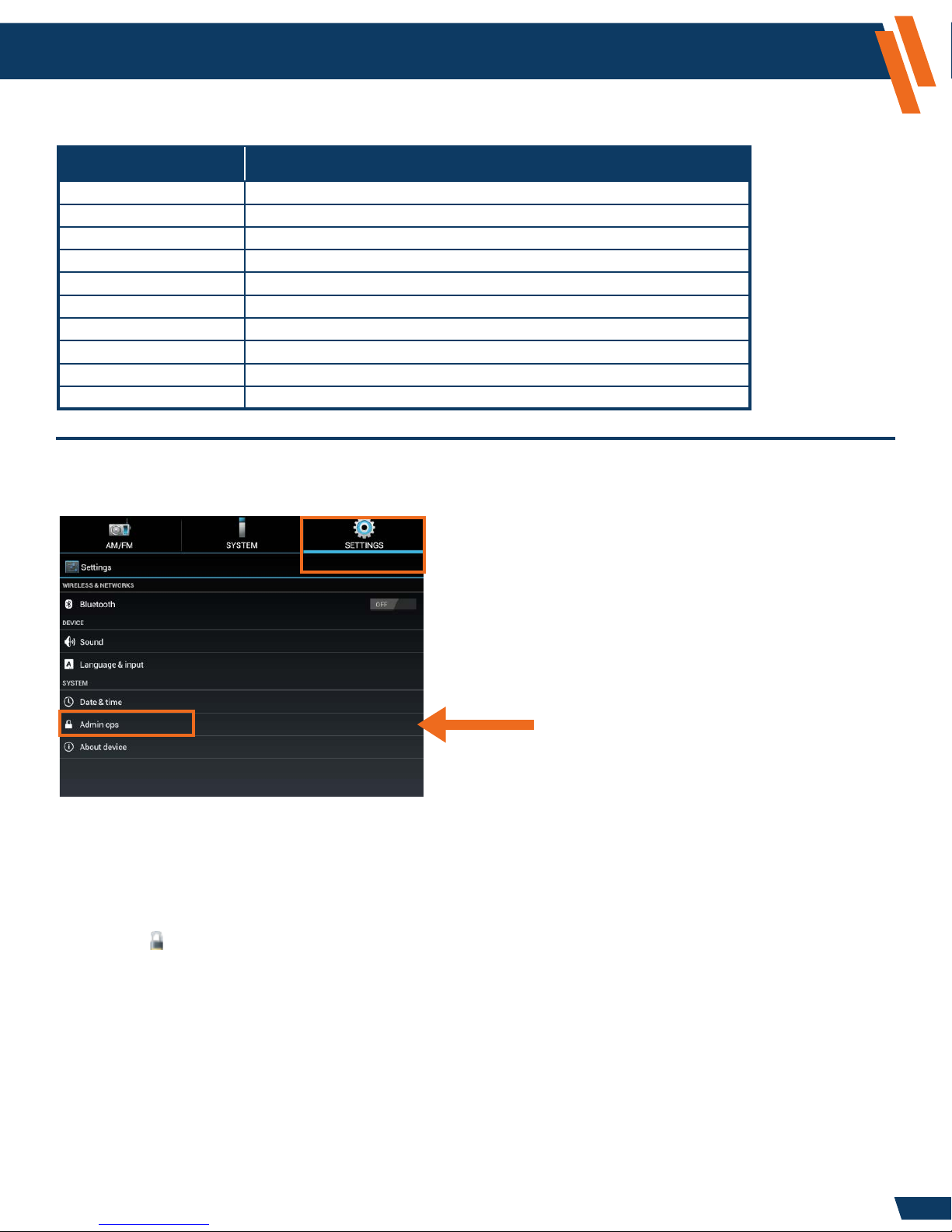
The “Admin Ops” section is password protected to prevent unauthorized access to the
system congurations settings.
To change System Settings perform the following steps:
1. Select the Settings icon from the “Tab Selection” area at the top of the screen.
2. Select Admin Ops.
3. Select Access Control.
4. Select Log in.
5. A “Login Required” window will appear. When asked for the Administrator password enter
the following:
a. Password: 0000 (Four Zeros)
NOTE: This is the System Default Password, to Change Password see Page 10.
b. Select Log in.
You are now logged in as Administrator. To log out of Administrator, perform the steps above;
however at Step 4, select Log out.
To conrm you are logged in as the Administrator, select the Notication area at the lower
right-hand corner of the screen. You will see “Access Control – Currently logged in as Administrator”.
9
Page 10
Configuration and Setup (continued)
Changing the Administrator Password
1. Select the Settings icon from the “Tab Selection” area at the top of the screen.
2. Select Admin Ops.
3. Select Access Control.
4. Select Change Password.
5. Enter current password into Password eld.
6. Enter in a new password into New Password and Conrm Password elds.
7. Select OK.
Your password is now changed.
www.havis.com
1-800-458-3410
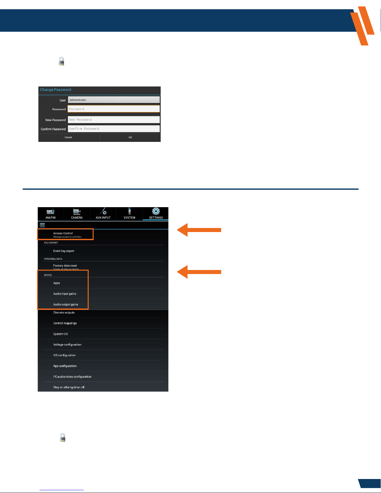
Settings Application - Administrator Operations - Access Control
Setup Administrator Protection
and Password
Device conguration
(touch and swipe upward
to scroll for more options)
Enable User Account Control (checkbox)
The ICS has the ability to limit the user’s access to modify system settings. By default the
system is locked. To limit the user’s access system settings, perform the following steps:
1. Select the Settings icon from the “Tab Selection” area at the top of the screen.
2. Select Admin Ops.
3. Select Access Control.
4. Select Enable user access control.
If the box is checked (default state), the user will need to enter the administrative password
to change settings. If the box is unchecked, then all operations are available without the
administrative password.
10
Page 11
Configuration and Setup (continued)
www.havis.com
1-800-458-3410
Settings Application - Administrator Operations - File Export
Event Log Export
This setting allows you to send diagnostic data back to Havis. In the event of a system issue, please
contact Havis Technical Support at 1-800-458-3410. If Havis requests an Event Log Export to
assist with the support of your system, perform the following steps:
1. Insert a USB Memory Stick into the USB port found on the dash.
2. Select the Settings icon from the “Tab Selection” area at the top of the screen.
3. Select Admin Ops.
4. Select Event Log Export.
5. An “Event Log Export” window will appear, press OK to begin the export process, or
press Cancel to stop the process.
6. The system will conrm when the export was successful. Select OK to complete the process.
On the USB Memory Stick, you will nd the Event Log Export process has created an “Exports”
folder containing a sub-folder named similar to “2015_01_01_at_08_05_30”. The entire
sub-folder should be sent to Havis Technical Support for evaluation.
Settings Application - Administrator Operations - Personal Data
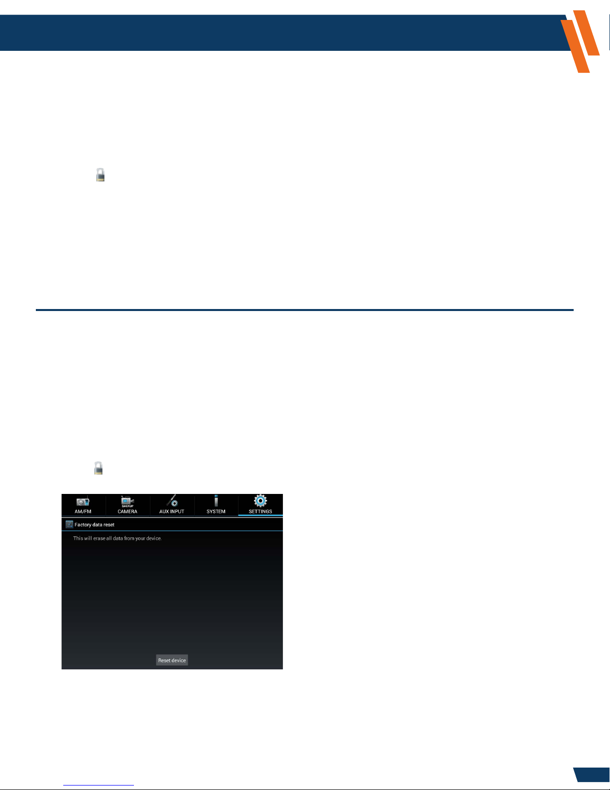
Factory data reset
This setting allows you to restore all system settings to the factory defaults. This will overwrite
any existing preferences and user adjustments. This should not be done without specic direction
from the Havis Technical Support Team.
To perform a Factory data reset perform the following steps:
1. Backup all system settings prior to performing this step.
(refer to ICS Conguration > Export, Page 16, for directions)
2. Select the Settings icon from the “Tab Selection” area at the top of the screen.
3. Select Admin Ops.
4. Select Factory data reset.
5. Select the Reset device button.
6. A window will appear stating, “Erase all data? You can’t reverse this action.”
7. Select Erase Everything.
This process may take several minutes to complete.
11
Page 12
Configuration and Setup (continued)
Settings Application - Administrator Operations - Device
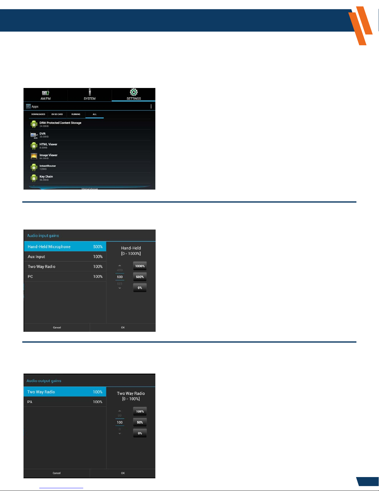
Apps
This setting provides a standard Android view of the running applications and processors.
This section is normally only used for diagnostic purposes and should not be used without
direction from the Havis Technical Support Team.
www.havis.com
1-800-458-3410
Audio Input Gains
This setting allows the system administrator to adjust the relative volume levels for the various inputs.
NOTE: Hand-Held Microphone and Two Way Radio (optional)
Audio Output Gains
This setting allows the system administrator to adjust the audio output volume levels.
NOTE: Two Way Radio and PA (optional)
12
Page 13
Configuration and Setup (continued)
www.havis.com
1-800-458-3410
Settings Application - Administrator Operations - Device (continued)
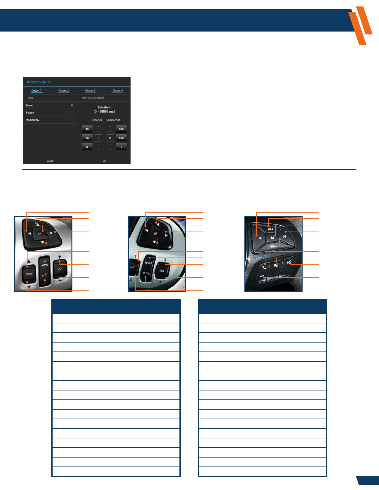
Discrete Outputs
This setting allows the system administrator to select the behavior of each discrete output (timed, toggle,
or momentary).
NOTE: Discrete outputs (optional)
Control Mappings
The ICS provides exible control options for vehicle functions. The control logic can map steering
wheel to output functions. The Ford steering wheel controls are supported as part of this logic.
Standard Ford Steering Wheel controls.
5-Way Left
5-Way Up
5-Way OK
5-Way Right
5-Way Down
Special Ford Steering Wheel controls.
5-Way Left
5-Way Up
5-Way OK
5-Way Right
5-Way Down
Model Year 2016-17 Utility Steering Wheel controls.
Seek Down
Volume Up
Media
Seek Up
Volume Down
Seek Up
Phone
Volume Up
Volume Down
PTT
Seek Down
Available Input Controls Available Output Functions
5-Way Down AM/FM Radio Band AM
5-Way Left AM/FM Radio Band FM
5-Way Ok AM/FM Radio Band WB
5-Way Right AM/FM Radio Preset Down
5-Way Up AM/FM Radio Preset Up
Media AM/FM Radio Seek Down
Mute AM/FM Radio Seek Up
PPT AM/FM Radio Tune Down
Phone AM/FM Radio Tune Up
Phone Down Entertainment Audio Mute Toggle
Phone Up Hands Free Mic
Seek Down System Brightness
Seek Up System Mode
Volume Down System Volume Down
Volume Up System Volume Up
Output Relay 1-4* Output Relay 1-4*
Not Supported
Media
Not Supported
Not Supported
Mute
Not Supported
Phone Voice Toggle
* Output Relay 1-4 (optional)* Output Relay 1-4 (optional)
Phone
Mute
Not Supported
Not Supported
13
Page 14
Configuration and Setup (continued)
www.havis.com
1-800-458-3410
Settings Application - Administrator Operations - Device (continued)
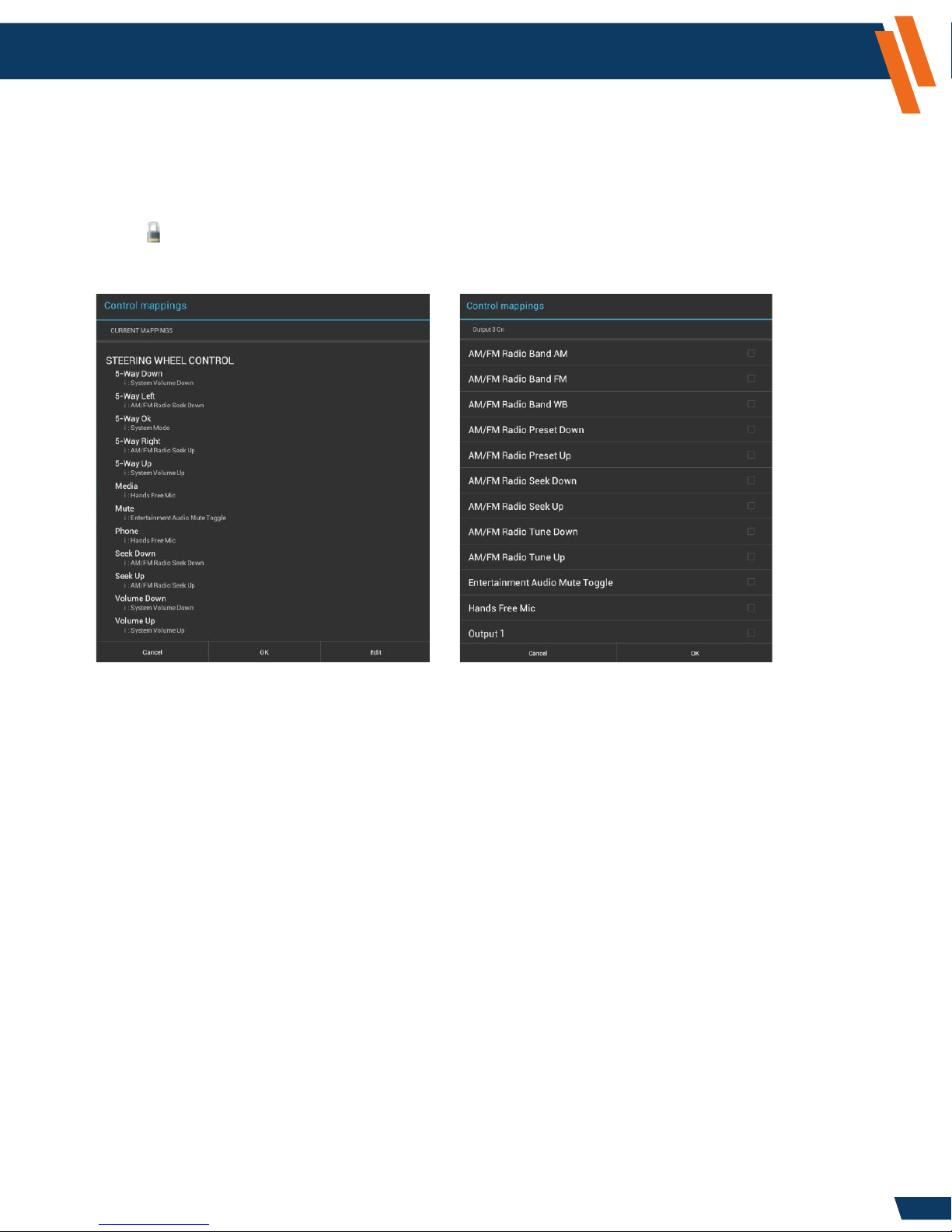
Control Mappings (continued)
This setting allows you to congure desired functions for the steering wheel controls.
To view the current control mappings perform the following steps:
1. Select the Settings icon from the “Tab Selection” area at the top of the screen.
2. Select Admin Ops.
3. Select Control Mappings.
4. A “Control Mappings” window will appear with a summary of the current mappings.
To edit the current mappings, perform the following steps:
1. Select the Edit button as seen above.
2. Select the item that you wish to edit, for example: 5-Way Left.
3. A window will appear; all active items will have a check mark located within the box to the
right of the control.
4. Scroll to select your desired control.
5. Select your desired row, and the check mark will appear when the action has been assigned.
6. Select OK.
7. Select the next item you wish to edit, if desired. If complete, select OK.
8. The System will show you the updated Control Mappings Summary. If you are done with
modifying your settings, select OK. If not, go back up to step 1 and repeat as necessary.
9. A window will appear stating “Control Mappings - Updating settings, this will take a few seconds.”
14
Page 15
Configuration and Setup (continued)
www.havis.com
1-800-458-3410
Settings Application - Administrator Operations - Device (continued)
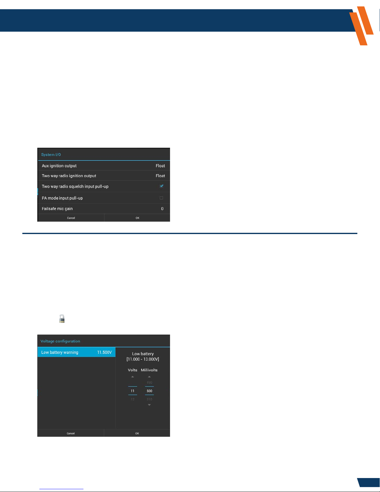
System I/O
This setting allows you to congure hardware characteristics for some of the device control pins.
The correct settings depend on the specic system implementation. Please contact Havis Technical
Support prior to changing any of these settings.
1. Select the Settings icon from the “Tab Selection” area at the top of the screen.
2. Select Admin Ops.
3. Select System I/O.
4. Select Two way radio squelch input pull-up if you do not have the two way radio option for the ICS.
This setting allows the AM/FM/WB Radio to utilize the in-vehicle speaker system.
NOTE: Contact Havis Technical Support prior to adjusting any other settings.
If you do not have the two way radio
option for the ICS, then you will need
to select the Two way radio squelch
input pull-up, so a check mark is
placed in the box. This will enable
audio on the ICS.
Voltage Conguration
This setting allows you to modify the default setting for the vehicle’s battery voltage, which is
displayed at all times in the lower right-hand corner of the Touch Screen Display. If your vehicle
is operating above the Low Battery Warning level; the voltage will be displayed in Blue text. If your
vehicle is operating below the Low Battery Warning, the voltage will appear in red, and a system
notication will appear. By default the Low Battery Warning is set at 11.500V. If you desire to
change the Voltage Conguration default setting, perform the following steps:
1. Select the Settings icon from the “Tab Selection” area at the top of the screen.
2. Select Admin Ops.
3. Select Voltage conguration.
4. Adjust the Volt and Millivolts to your desired setting (11.000 - 13.000V) by using the Up or Down
icons or by swiping your nger over the Volts or Millivolts numbers.
5. Select OK.
The ICS has an automatic shutdown procedure, which is xed at 10.5V.
15
Page 16

Configuration and Setup (continued)
www.havis.com
1-800-458-3410
Settings Application - Administrator Operations - Device (continued)
ICS Conguration
This setting allows you to Export, Import and Reset all system conguration settings. This will allow
administrators to congure their ICS and save them to a USB Memory Stick. By doing this, the
administrator can then Import the settings across their entire eet without having to go through
each step on each vehicle. The export le can serve as a backup le for the conguration settings chosen.
To Export your System Conguration Settings, perform the following steps:
1. Insert a USB Memory Stick into the USB port found on the dash.
2. Select the Settings icon from the “Tab Selection” area at the top of the screen.
3. Select Admin Ops.
4. Select ICS Conguration.
5. Select Export.
6. A window will appear “Export Completed Successfully.”
7. Select OK.
To Import your System Conguration Settings, perform the following steps:
1. Insert a USB Memory Stick that has the saved ICS Conguration into the USB port found on the dash.
2. Select the Settings icon from the “Tab Selection” area at the top of the screen.
3. Select Admin Ops.
4. Select ICS Conguration.
5. Select Import.
6. A window will appear “Import in progress, press the back button to cancel.”
This process may take a minute.
7. When the process is complete, you will return to the main Video Display.
To Reset your System Conguration Settings, perform the following steps:
1. Select the Settings icon from the “Tab Selection” area at the top of the screen.
2. Select Admin Ops.
3. Select ICS Conguration.
4. Select Reset.
5. A window will appear “Are you sure you want to reset the ICS Conguration to the factory defaults?
This operation cannot be undone.”
6. Select OK.
This process may take a minute to complete.
16
Page 17

Configuration and Setup (continued)
www.havis.com
1-800-458-3410
Settings Application - Administrator Operations - Device (continued)
ICS Conguration (continued)
ICS Conguration Export
Settings Path Setting Saved Factory Default
Settings > Sound >
Mixer
Settings > Admin Ops >
Audio Input Gains
Settings > Admin Ops >
Audio Output Gains
Settings > Admin Ops >
Discrete Outputs
Settings > Admin Ops >
Command Routings
Settings > Admin Ops >
System I/O
Settings > Admin Ops >
Voltage Conguration
Settings > Admin Ops >
App Conguration
Settings > Admin Ops >
PC Audio/Video Conguration
Settings >
Admin Ops >
Stay on after ignition off
Image Viewer App Image Viewer Image No Image
OS Sounds 100%
AM/FM Radio 100%
AUX Input 100%
Bluetooth Phone (Optional) 100%
Two-Way Radio (Optional) 100%
PC 100%
HVAC Beep 50%
Hand-Held Microphone (Optional) 500%
AUX Input 100%
Two Way Radio (Optional) 100%
PC 100%
Two Way Radio (Optional) 100%
PA (Optional) 100%
Outputs 1 – 4 (Optional) Toggle
5-Way Left AM/FM Radio Seek Down
5-Way Up System Volume Up
5-Way Right AM/FM Radio Seek Up
5-Way Down System Volume Down
5-Way OK System Mode
Phone (Media) Hands-Free Microphone
PPT (Mute) Entertainment Audio Mute Toggle
Seek Down AM/FM Seek Down
Seek Up AM/FM Seek Up
Volume Down System Vol. Down
Volume Up System Vol. Up
Aux Ignition Output (Future) Float
Two Way Radio Ignition Output (Future) Float
Two Way Radio Ignition Squelch Input Pull-Up Checked
PA mode Input Pull-Up (Optional) Unchecked
Failsafe Mic Gain (Optional) 0
Low Battery Warning 11.5V
Top Apps AM/FM, System, Settings
Bottom Apps Image Viewer
PC Video Alignment PC performs automatic alignment
PC Audio Interface USB
Stay on after ignition Off
Stay on 30 min.
Default action Stay on
Take default action after 30 sec.
(most)
17
Page 18

Configuration and Setup (continued)
www.havis.com
1-800-458-3410
Settings Application - Administrator Operations - Device (continued)
App Conguration
This setting allows you to customize the view of your Video Display 1 and control which applications
appear on the Top and Bottom window.
1. Select the Settings icon from the “Tab Selection” area at the top of the screen.
2. Select Admin Ops.
3. Select App Conguration.
4. The Available applications are listed on the left, and the Congured applications are listed on the right.
Use the left and right arrows to move applications between Available/Congured.
5. The Congured applications are split between a single, always-present application in the Bottom
Window, and multiple applications that are placed in the Tab Selection area at the top of the screen.
Use the up and down arrows to move applications between the Top/Bottom window and to change
the order in which the icons appear at the top of the screen.
6. Select OK.
7. A window will appear “Changes will now be applied. This will result in all apps being closed.”
8. Select OK.
This process may take a minute.
The AM/FM audio will be muted, and you
will need to unmute on the AM/FM screen.
PC Audio/Video Conguration
This setting allows you to congure audio/video control for the Computer, Laptop or Tablet that is remotely
connected to the ICS via an A/V Extender. Most remotely connected computers will automatically
align video to the ICS Touch Screen Display; however, some devices will not automatically align video
to the ICS Display. If you need to adjust the video alignment on the Touch Screen Display, perform
the following steps:
1. Select the Settings icon from the “Tab Selection” area at the top of the screen.
2. Select Admin Ops.
3. Select PC audio/video conguration.
4. Select PC video alignment.
5. A window will appear “PC video alignment.” Select PC does not perform automatic
alignment (some tablet docks).
To change the setting back, perform the above steps, but on step 4, select PC performs
automatic alignment (most).
NOTE: You can not congure both the NTSC Camera and the Backup Camera
at the same time.
18
Page 19

Configuration and Setup (continued)
www.havis.com
1-800-458-3410
Settings Application - Administrator Operations - Device (continued)
PC Audio Interface
This setting congures the PC audio over either a USB port or Analog audio cable. Havis recommends
using PC Audio over USB. Audio over USB does not require an Analog audio cable, but will still work
if the Analog audio cable is attached between the A/V Extender and PC. The ICS will use Audio over
USB as the default setting.
If you want to change to use the Analog audio cable, make sure the audio cable is installed and perform
the following steps:
1. Select the Settings icon …
2. Select Admin Ops
3. Select PC audio/video conguration
4. Select PC audio interface
5. A window will appear “PC audio interface”. Select Analog.
To change the setting back, perform the above steps, but on Step 5, select USB.
19
Page 20

Configuration and Setup (continued)
www.havis.com
1-800-458-3410
Settings Application - Administrator Operations - Device (continued)
Stay On After Ignition Off
By default, this setting is disabled, and when ignition is OFF, the ICS will enter Standby after 10 minutes
(unless the door is opened beforehand). This setting allows you to congure the ICS to stay on for
15 to 90 minutes, congure the default action, and set a timer to take this default action.
Once the key is in the OFF position, a pop-up window will appear allowing you to override your default
action (Stay on or Standby). If an override is not selected, then the default action occurs. If the ICS
is in Video Display 2 mode, the pop-up window will not appear after ignition off and the default action
will occur.
A Stay on icon will appear in the notication status bar when active (orange stop watch).
Pressing the Stay on icon will open the notication window and list the time remaining in Stay on.
Pressing the Stay on icon in the notication window will open another pop-up window allowing you
to continue to Stay on or enter Standby.
During Stay on, only the top row of the HVAC buttons will be operational (POWER, ILLUMINATION, MODE,
VOLUME).
The key must be in ACC or ON positions to modify the Stay on feature.
1. Select the Settings icon from the “Tab Selection” area at the top of the screen.
2. Select Admin Ops.
3. Select Stay on after ignition off.
4. A window will appear. Check the box for Stay on after ignition off. This will allow the Stay on
settings to be modied.
5. Select Stay on to adjust from 15, 30, 45, 60, or 90 minutes. Select OK.
6. Select Default action, then select Stay on or Standby.
7. Select Take default action after to adjust from 0 to 60 seconds. Select OK.
20
Page 21

Configuration and Setup (continued)
www.havis.com
1-800-458-3410
Settings Application - Administrator Operations - Device (continued)
Software Update
To check your current Firmware version, perform the following steps:
1. Select the Settings icon from the “Tab Selection” area at the top of the screen.
2. Select About Device.
3. Build number = P3.x.x indicates the rmware revision.
4. The Havis website will always contain the most recent software version and the corresponding
Release Notes. Registered users will be notied by email of software revision updates.
If your system is not using the most recent software revision, perform the steps below:
5. Download the latest software revision from the www.havis.com, and save the le to a
USB Memory Stick. (NOTE: Do not unzip or rename the le)
5A. Go to www.havis.com.
5B. Click on the Support tab.
5C. Under Helpful Links > Product Support, click on Integrated Control System (ICS).
Under Technical Support & Downloads, click on Download the Latest Software.
5D. Enter a password into the text eld. For the correct password, contact Havis Technical
Support (1-800-458-3410). Then click Submit.
5E. The Latest Software Revision will be listed (P8500-dcm-Lectronix-P3.x.x), click the link to download.
5F. Copy the latest software le, P8500-dcm-Lectronix-P3.x.x, from your computer onto a USB memory stick.
21
Page 22

Configuration and Setup (continued)
www.havis.com
1-800-458-3410
Settings Application - Administrator Operations - Device (continued)
Software Update (continued)
6. Conrm the ICS System is turned on, then insert the USB Memory Stick that has the saved
rmware into the USB port found on the dash.
7. Select the Notication Bar on the Touch Screen Display.
8. Select USB rmware update.
9. A message will appear in the “Top Window” of the Touch Screen Display, showing the
current rmware version and the rmware version on the USB Memory Stick.
10. Select Install.
11. A window will appear:
12. After the rmware had been copied to the ICS, the following message will appear:
13. Select Reboot.
This may take several minutes. Do not remove power or otherwise disturb the device during the rmware update process.
NOTES: • Only one software update le should be placed on the USB memory stick. If you have both previous
and latest software les on the USB Memory Stick, the ICS will give you an error message.
• Do not rename the software update le.
• The software update le should be in the top level directory of the USB Memory Stick
(i.e. Do not place in sub-folder).
Software Update via Attached Laptop, Computer or Tablet
You can update your eet of vehicles by sending a Windows executable le to each vehicle. When
the le named ICSUpdate<version>.exe is run from the attached laptop, computer or tablet, it transfers
the rmware update to the ICS, performs the update and reboots the ICS. You can conrm the update
to the new rmware in Settings > About Device > Build Number = P3.x.x. To support this feature, the
ICS creates a mass storage device “ICS_EP” of 320MB on the attached laptop, computer or tablet.
The storage device, ICS_EP, can only be used for the ICS update process.
22
Page 23

Configuration and Setup (continued)
Sound
- OS Volumes (control volume level for Media, Notications
and Alarms)
- Mixer (OS Sounds, AM/FM Radio, Aux Input, Bluetooth
Phone, PC, HVAC Beep)
- Tone (Bass & Treble)
- Balance/Fade (Left, Right, Front, Back)
- Speed Controlled Volume (High, Medium, Low, Off)
- Default Notications (list of possible notication sounds)
- Touch Sounds (check box)
Language & Input
- Language (English (United States) and English (Canada)).
Changing Language to English (Canada) will change
outside temperature to Celsius.
- Spelling correction (check box)
- Personal Dictionary (ability to add words to dictionary)
- Default Keyboard (English only currently)
- System Keyboard (Auto-Capitalization, Sound on keypress,
Popup on keypress, show settings key, Voice input key)
- Physical Keyboard (Auto-replace, Auto-capitalization,
Auto-punctuate)
- Mouse/Trackpad (pointer speed)
www.havis.com
1-800-458-3410
Date & Time
1. Select Set Date
2. Change Month, Date, and Year by pressing the Up or
Down Arrows or by Scrolling with nger swipe
3. Select OK
4. Select Set Time
5. Change Hour, Minute, and AM/PM by pressing the Up
or Down Arrows or by Scrolling with nger swipe
6. Select OK
About Device (for diagnostics and troubleshooting)
- Model Number
- OS Version
- Build Number (lists the software version of the ICS)
- Serial Number (Embedded Processor)
- Touch Screen Display serial number
- Audio/Video Extender 1 serial number / Audio/
Video Extender 2 serial number
- Embedded Processor application version /
bootloader version
- HVAC and Touch Screen Display Controls application
version / bootloader version
23
Page 24

Configuration and Setup (continued)
AM/FM/WB Radio Application
This application allows tuning and control of the vehicle radio.
www.havis.com
1-800-458-3410
A
D
B E
C
Button Description
A. MUTE Press to completely disable AM/FM/WB audio. A blue line under the icon will be present
when the system is not muted.
B. SEEK / SCAN SEEK:
Press and release Up or Down arrows to go to the next or previous preset radio station.
SCAN:
Press and hold Up or Down arrows to search for the next or previous strong radio
station frequency.
C. PRESET To set the Preset buttons:
1. Tune to a radio station then press and hold one of the Preset buttons.
2. Repeat until all desired presets are stored.
(Additional presets are available by touching the FM1/FM2 button (far right), which toggles
between two sets of Presets)
D. BAND Three buttons to choose a radio frequency band (FM, AM, or WB).
(The Weather Band (WB) consists of 7 channels. You should tune between these 7 channels
to nd a weather channel that services your area.)
E. TUNE Press Up or Down arrows to manually search the frequency band.
AUX Input Application
This application allows you to connect an external audio source through a 3.5mm Audio Jack in the
dash panel on vehicles equipped with SYNC. The application allows simple muting or unmuting of
the auxiliary audio source.
If your AUX Input application is not available, please refer to App Conguration on Page 18
24
Page 25

Configuration and Setup (continued)
www.havis.com
1-800-458-3410
NTSC Camera Application
This application allows you to stream live video footage to the Touch Screen Display. The application
accepts NTSC Video Format (RCA Jack or Plug); however, does not provide outgoing touch screen control
or recording capabilities.
This application is mutually exclusive with the Backup Camera application so only one of the other can
be selected at a time.
If your NTSC Camera application is not available, please refer to App Conguration on Page 18
Backup Camera Application
When the Backup Camera application is congured in the top window, it will pop-up and stream live
video while the vehicle is in Reverse gear. When the vehicle exits the Reverse gear, the previous application
will be shown in the top window. If the Backup Camera is congured in the bottom window, it will always
be present.
This application will only be shown in Video Display 1 mode. If the ICS is in Video Display 2 or Lights Out
mode, the Backup Camera application will not pop-up when entering Reverse gear.
This application is mutually exclusive with the NTSC Camera application so only one or the other can be
selected at a time.
If your Backup Camera application is not available, please refer to App Conguration on Page 18
AUX Camera Application
This application allows you to stream video from
an externally connected digital video recorder (DVR).
This option requires an optional A/V Extender 2 component.
If your AUX Camera application is not available,
please refer to App Conguration on Page 18
25
Page 26

Configuration and Setup (continued)
www.havis.com
1-800-458-3410
Clock Application
The Clock Applicationprovides the current time and date. It can be shown by selecting the
Clock application at the top of the display. If your Clock application is not available, please
refer to App Coguration on Page 18.
Phone Application
The Bluetooth Phone feature is optional and requires the purchase of Havis P/N ICS-A-0013 for a cable
and antenna kit. Once this kit is installed, you will need to add the Phone application (refer to App
Conguration on page 18).
1. Select the Phone application.
2. Select the Bluetooth Settings icon.
3. Press the OFF/ON button to turn Bluetooth off/on.
When Bluetooth is enabled, an icon is shown at the bottom
of the display to the left of the temperature reading.
When Bluetooth ON but not connected to a phone, icon is Gray.
When Bluetooth ON and connected to a phone, the icon is Blue and
the phone battery level and signal level indicators appear.
26
Page 27

Configuration and Setup (continued)
www.havis.com
1-800-458-3410
Phone Application (continued)
4. Press “SEARCH FOR DEVICES” to see devices that are available for pairing. If you do not see your
device listed under AVAILABLE DEVICES, you need to go to your Phone’s Settings, select Bluetooth,
and make your phone visible to other devices.
5. Press a device in the list of AVAILABLE DEVICES to initiate pairing.
6. Verify any codes displayed and press Pair.
Also, you must press OK on your phone to accept the ICS pairing.
Once paired, you will see a display similar to below:
7. Select the 3 stacked dots to the right of SEARCH FOR DEVICES to adjust the Visibility timeout
or to Rename the ICS (default name). The Visibility timeout is how long the ICS remains visible
to nearby devices and can be adjusted from 2 minutes, 5 minutes, 1 hour or Never time out.
27
Page 28

Configuration and Setup (continued)
www.havis.com
1-800-458-3410
Phone Application (continued)
8. Once the phone is paired with the ICS, selecting the Phone application will bring up the phone keypad.
9. Enter the phone number on the keypad and press the phone button to the right of the keypad
to initiate the call.
10. The device can be unpaired by pressing “Unpair”.
11. The device can remain paired but unusable for phone operation by unchecking
the “Phone audio” checkbox.
12. You can also turn Bluetooth on/off from the Settings application.
28
Page 29

Configuration and Setup (continued)
System Application
This application provides system diagnostic information
for the ICS components.
Power Status
GREEN Indicates the component is connected properly to vehicle power.
RED
GREEN Indicates the component is communicating appropriately.
RED
GRAY Indicates no power. See Wiring Diagram on page 41.
Indicates the component is not connected properly to vehicle power or a low voltage
warning is present. See Wiring Diagram on page 41.
Link Status
Indicates the component is not communicating properly. The Embedded Processor
Link may turn Red in Stay On mode. See Wiring Diagram on page 41 to make sure ICS
is connected properly. A Red Link for Audio/Visual Extender 1 indicates an issue with
the Red CAT6A cable. A Red Link for Touch Screen Display indicates an issue with the
Blue CAT6A cable.
www.havis.com
1-800-458-3410
Video Status
GREEN
RED
GRAY
Indicates the ICS is receiving proper video from the A/V Extender.
Indicates the ICS is not receiving proper video from the A/V Extender. Conrm
resolution is set to either 800x1280, 1024x1280 or 1024x1600, portrait orientation,
and driving a second monitor (Duplicate, Display only on 2 or Extended Mode).
See Wiring Diagram on page 41.
Indicates no power or no connection. Conrm computer, laptop or tablet is powered
on. See Wiring Diagram on page 41.
Temp Status
GREEN Indicates the component is operating within desired temperature ranges.
RED
Gray generally indicates an unknown or unused status on all measures
Indicates the component is not operating within desired temperature ranges. Contact
Havis Technical Support at 1-800-458-3410.
29
Page 30

Configuration and Setup (continued)
www.havis.com
1-800-458-3410
Image Viewer
This application is intended to give the user the ability to display an image on the Touch Screen
Display. Activate the Image Viewer application by selecting either the Image icon from the
“Tab Selection” area in the top window, or by selecting Image Viewer if congured in the bottom
window. If the “IMAGE” application is not shown as an option, you must rst add it to the
congurable application list (see App Conguration on page 18).
To import an image, perform the following steps:
1. Save your desired image onto a USB Memory Stick with a le name “image.png” formatted
to 800 x 480 resolution.
2. Insert a USB Memory Stick that has the saved image into the USB port found on the dash.
3. Touch anywhere in the Image Viewer window to make it active.
4. A title bar will appear. Select the three stacked dots.
5. Select Import Image.
4
5
6. Your Image will now appear on the Image Viewer.
30
Page 31

Configuration and Setup (continued)
www.havis.com
1-800-458-3410
Congure Computer, Laptop, or Tablet
Using the ICS Touch Screen Display as a Secondary Monitor (Video Display Mode 2)
Setting up your Computer, Laptop or Tablet to use the ICS Touch Screen Display as a Secondary Display
may vary depending on your operating system and video driver that is installed on your device.
The below section will walk you through how to make the necessary changes on most devices.
ICS Touch Screen Display Settings
Optimal Resolution: 800 x 1280 (With an updated A/V Extender and the latest software,
1024x1280 and 1024x1600 resolutions are available)
Screen Orientation: Portrait
NOTE: 768 x 1024 resolution is also supported, but the image will not ll the ICS display as indicated
by the ½” blank band at the top and bottom of the display. The ICS touchscreen is only aligned
to a full screen image. The touchscreen will be off when displaying a 768 x 1024 resolution.
Screen Resolution Settings
Display Resolution Orientation Multiple Displays New AVX Required Refresh Rate
ICS Display 800x1280 Portrait Show desktop only on 2 No 60Hz
ICS Display 1024x1280 Portrait Show desktop only on 2 Yes 47Hz
ICS Display 1024x1600 Portrait Show desktop only on 2 Yes 45Hz
Most laptops have keyboard shortcuts to enable external video displays (see Keyboard Shortcuts below).
In the event your device doesn’t have this functionality or the setting is disabled, follow Operating System
Control Panel Instructions below.
Keyboard Shortcuts to active External Monitor
To use keyboard shortcuts to change the display settings, each device’s specic key sequence will vary.
Typically it is either: Fn + F3, F4, F5, F8, or F9. For example the Panasonic CF-19 Mark IV, you need to press
and hold Fn + F3 at the same time, which will switch between Computer Only, Duplicate, Extend and
Projector Only display modes. Select the Projector Only mode. The appropriate “F” Key will be labeled
as CRT/LCD or have a picture of a monitor on the key or close to the key. If this combination is unsuccessful,
contact your System Administrator.
31
Page 32

Configuration and Setup (continued)
Congure Computer, Laptop, or Tablet (continued)
Control Panel Instructions to active External Monitor
Windows XP
1. Open Display in Control Panel.
2. On the Settings tab.
3. Click the Identify button to see which screen you are adjusting
4. Be sure the Integrated Control System Touch Screen Display is marked
as “Use this device as the primary monitor.”
5. Be sure “Extend my Windows Desktop onto this monitor” is not selected.
6. Select the ICS Touch Screen Display and adjust resolution to 800 x 1280.
7. Click Apply and Click OK.
www.havis.com
1-800-458-3410
NOTE: If the “Use this device as the primary monitor” option is grayed out, your video driver
has taken over the standard windows functions. Some drivers allow you to right click
on the desktop, select “Graphics Options”, “Output To” and then select “Monitor”.
32
Page 33

Configuration and Setup (continued)
Congure Computer, Laptop, or Tablet (continued)
Control Panel Instructions to activate External Monitor
Windows 7
Project to ICS Touch Screen Display
1. Press the Windows Key + P.
2. The below screen will appear, select “Projector only.”
Change Screen Resolution
1. Right Click on Desktop and select Screen Resolution.
2. Adjust resolution to 800 x 1280.
3. Adjust orientation to Portrait.
Windows 8 & Windows 10
Project to ICS Touch Screen Display
1. Go to the Start Screen.
2. Search for “Project to a second screen.”
3. Select “Second screen only.”
www.havis.com
1-800-458-3410
Change Screen Resolution:
1. Go to the Start Screen.
2. Search for “Change Screen Resolution.”
3. Adjust resolution to 800 x 1280.
4. Adjust orientation to Portrait.
33
Page 34

Configuration and Setup (continued)
www.havis.com
1-800-458-3410
Congure Computer, Laptop, or Tablet (continued)
Computer Setup Example
Panasonic Toughbook CF-31 Computer Setup Example:
CF-31A (Mark1 Perf/Std)
Windows 7 (64-bit)
HDMI video cable
In this example, the CF-31 will be set to have a blank display and project its contents onto the ICS Display.
1. Right-Click on Desktop and select Screen Resolution.
2. Enter the values for Display, Resolution, Orientation and Multiple Displays as shown in gure
below and click Apply.
3. Press the MODE button on the HVAC control panel to view Video Display 2 mode.
4. If the ICS is not displaying properly, follow the steps below.
5. In the Screen Resolution window, select Advanced Settings.
6. Select the Intel Graphics and Media Control Panel Tab.
7. Click on Graphic Properties.
34
Page 35

Configuration and Setup (continued)
Congure Computer, Laptop, or Tablet (continued)
Computer Setup Example (continued)
8. Select Display > General Settings.
9. Enter the values for General Settings as shown below.
www.havis.com
1-800-458-3410
10. Select Display > Multiple Displays.
11. Enter the values for Multiple Displays as shown below.
12. If “ICS Display” or “PCIM” is not shown as a Display option, try rebooting the CF-31 computer
and/or the ICS.
13. Try other Multiple Display settings (Extended Desktop or Clone Displays).
14. Conrm you are using the latest Graphics driver from Panasonic’s website.
35
Page 36

Configuration and Setup (continued)
www.havis.com
1-800-458-3410
Congure Computer, Laptop, or Tablet (continued)
Setting your device’s appropriate Power Management Settings
Congure your device to turn on when you turn the vehicle on
1. Turn on the computer and press the appropriate key(s) to enter the BIOS setup
(Typically, F2 or DEL keys)
2. Find the “POWER ON AC” or “AC INITIATION” setting and select “ENABLE.”
3. Save Settings and restart the computer.
Congure your device to remain on while docked
1. Click the Start button
2. Select Control Panel
3. Select Power Options
4. On the left hand side of the window, select “Choose when the computer sleeps”
5. Select “Never” for all options under “Plugged In”
6. Select Save changes
7. On the left hand side of the window, select “Choose what closing the lid does”
8. Select “Do Nothing” for both “Battery” and “Plugged In”
9. Select Save changes
10. Select Change plan settings
11. Select Change advanced power settings
12. Locate the USB settings
13. Under USB selective suspend settings, set to DISABLE for both “Battery” and “Plugged In”
14. Select Apply
15. Select the speaker icon in lower right corner of display. Set the volume level to 90%
Congure your Touch settings:
1. Click the Start button and enter “run” in the box to search programs and les
2. Enter “regedit” and select OK
3. Click HKEY_CURRENT_USER, then click Control Panel and then click Mouse
4. On the right hand side of the window, double-click to open DoubleClickHeight.
Change from 4 to 64 and select OK
5. On the right hand side of the window, double-click to open DoubleClickSpeed.
Change from 500 to 900 and select OK
6. On the right hand side of the window, double-click to open DoubleClickWidth.
Change from 4 to 64 and select OK
7. Reboot your laptop for these changes to take effect.
To Increase text size:
1. Click the Start button
2. Select Control Panel
3. Select Ease of Access Center
4. Select Make the computer easier to see
5. Select Change the size of the text and icons
6. Select Medium 125% (or Large - 150%) and click Apply
36
Page 37

Configuration and Setup (continued)
Congure Computer, Laptop, or Tablet (continued)
Setting your device’s appropriate Power Management Settings (continued)
Congure your USB Audio:
1. Conrm USB cable (GSM70087) is plugged in between AVX and your dock or PC.
2. Open Control Panel, select Hardware and Sound, select Sound
3. On the Playback tab, select Speakers for ICS Audio, then select Set Default.
www.havis.com
1-800-458-3410
Conguration Check
The embedded processor, cable and vehicle architecture are evaluated for compatibility
by the software. If you receive a warning message for an incompatible embedded processor or
HVAC cable, you should contact Havis Technical Support at 1-800-458-3410 for further instructions.
37
Page 38

Component Specifications
Touch Screen Display
www.havis.com
1-800-458-3410
• 12.1” ultra-durable portrait display
• The Projected Capacitive Multi-Touch
Screen uses chemically strengthened glass
(use glass cleaner to clean screen)
• Optimized screen allows for use with wet
hands and/or gloves
• Power and video from a single cable from
Embedded Processor
• Internal heater automatically activated
below -20°C, ensuring the display remains
at proper operating temperature
• When the display temperature is below
minus 20°C (-4°F), a message will be played
over the vehicle speakers: “Display warming
up. Please wait.”
Resolution
Brightness 1200 NIT Daylight Readable
Viewing Angle 88° from all angles
Environmental
800 x 1280, 1024x1280,
1024x1600
-20°C to +70°C (-4°F to +158°F)
HVAC Controls
• Replaces factory HVAC (climate) controls,
hazards and airbag indication
• Optimal cockpit placement and compatible
with OEM factory wiring
• Use one touch MODE button to easily
alternate between the two displays
• Convenient Buttons for control of Touch
Screen Display: volume, display brightness
and blackout
• Fan speed, Temperature, and Volume are
displayed on Touch Screen Display when
changed
• An audible beep can be heard from system
speakers to indicate valid HVAC button press
Touch Technology Cap-Sense touch pad controls
Buttons
Environmental -40°C to +85°C (-40°F to +185°F)
16 controls with LED backlighting and status indication
38
Page 39

Component Specifications (continued)
Embedded Processor
www.havis.com
1-800-458-3410
Port Identication
Ford Radio Connector
(PWR, GND, CAN, SPKRS)
• Mounts in place of OEM AM/FM radio
module
• Controls AM/FM Radio, A/V Extender and
HVAC Controller
• Steering wheel control functionality is
highly customizable to provide “one push”
operation of critical functions
Police Radio/
Hand-Held Mic
Hands-Free Mic
(optional)
Emergency Warning Lights/
Public Address
(optional)
I/O
CAN, USB, RS232, Ethernet,
Audio, Video
Amplier 4 x 20W speakers
Radio AM/FM/WB tuner
Application
Framework
Android 4.1
Environmental -40°C to +85°C (-40°F to +185°F)
Bluetooth
AM / FM
Antenna
For Future Use
Antenna
(optional)
Touch Screen
Display
A/V
Extender 1
A/V
Extender 2
(optional)
Future Use
For
HVAC Serial,
AUX Audio,
NTSC
For
Future Use
USB 2.0
(x4)
KBD USB port is for
externally mounted keyboards.
This port provides power to
backlit equipped keyboards.
If an external keyboard is connected, the keyboard can
be used to input text or operate the mouse on the Touch
Screen Display. If no keyboard is installed, use the touch
screen to operate control. If text is required, press the
text eld, and an on-screen keyboard will appear.
39
Page 40

Component Specifications (continued)
A/V Extender
www.havis.com
1-800-458-3410
• Ability to remotely connect an external
audio/video source to the Touch Screen
Display such as PC, laptop, or tablet
• Connects VGA or HDMI, micro-USB*, and
Analog Audio to Embedded Processor
with a single shielded CAT6A cable,
which is designed for an automotive
environment
Inputs from PC VGA, HDMI, micro-USB*, Audio
Power Connection No separate power required
Environmental -40°C to + 85°C (-40°F to +185°F)
micro-USB only allows for the input of External
*
Keyboard, Mouse, and touchscreen feedback
The A/V Extender’s interfaces for connecting to the laptop or similar computer device include:
• VGA or HDMI video (HDMI supports video only, separate audio cable required).
If the external connected device only has DVI video output, a DVI-to-HDMI (active or passive)
adapter should be purchased. If the external connected device only has a DP video output,
a DP-to-HDMI (active only) adapter should be purchased.
• Audio (from computer, goes to vehicle speakers)
NOTE: The Audio cable is not required if the PC audio interface is set to USB (refer to page 19).
• USB (Keyboard, Mouse, and Touch Screen Display feedback to on-board computer)
Port Identication
VGA HDMI Audio USB LINK
HDMI SUPPORTS VIDEO ONLY.
To Docking Station,
PC, Laptop, or Tablet
To Embedded
Processor
A/V EXTENDER MUST BE PROPERLY
CONNECTED TO CHASSIS GROUND
40
Page 41

ICS Integration Overview
www.havis.com
1-800-458-3410
Wiring Diagram
The ICS has the following cables available. The cable set provided is specic to your order.
1) GSM70096: CAT6A (15 Ft. RED) – Embedded Processor to A/V Extender
2) GSM70085: CAT6A (3 Ft. BLUE) – Embedded Processor to Touch Screen Display
3) GSM70076 or GSM70111: Harness (16 pin) – Embedded Processor to:
a. HVAC Controller: HVAC Controller (8 Pin)
b. NTSC Video Input: RCA Jack (GSM70076) or
RCA Plug (GSM70111)
c. OEM HVAC Control: OEM Vehicle HVAC Control Harness (6 pin)
4) GSM70086: USB (3 Ft.) – Embedded Processor to Vehicle USB Panel Mount (Vehicles without SYNC only)
5) GSM70094: USB (6 Ft.) – Embedded Processor to Vehicle Console
6) GSM70091: USB (6 In.) – Embedded Processor to Vehicle USB Panel Mount Harness (Vehicles with SYNC only)
7) GSM70073: VGA – A/V Extender to Computer (PC, Laptop or Tablet)
8) GSM70089: HDMI – A/V Extender to Computer
9) GSM70074: Audio – A/V Extender to Computer
10) GSM70087: USB – A/V Extender to Computer
11) GSM70097: Sedan only – Splice Cable between Humidity Sensor and Console/Bracket.
12) GSM70112: Adaptor harness for Sedan or model year 2013-2015 Utility.
Must be removed for model year 2016-2017 Utility.
Please see the included Wiring Diagram for proper wiring installation
41
Page 42

Troubleshooting
www.havis.com
1-800-458-3410
The Havis ICS Support and Repair Policy can be found on the Integrated Control System FAQ webpage.
http://customers.havis.com/index.php/faqs-products/integrated-control-system
ISSUE POSSIBLE CAUSE(S) POSSIBLE SOLUTION(S)
ICS Issues
Conrm the vehicle key is in the ACC or RUN position to turn
system power on.
Conrm the rmware le you downloaded is not placed in a subfolder. The system will only recognize les saved at the top level.
Conrm there is only (1) downloaded rmware version saved on
When I follow the
Software Update section
of the manual, the ICS
doesn’t perform the
update procedure.
HVAC Control Buttons
don’t appear to be
working.
I cannot control the
rear vents with the HVAC
Controls.
I see a “No Video”
message displayed when
running the NTSC Camera
Application.
The ICS is frozen or locks
up during operation.
ICS lost the Date and Time.
Your USB Memory stick
may not be setup/
congured properly.
Vehicle Power may not
be on.
Your HVAC System may not
be on.
Need to reset the ICS.
HVAC not at latest
rmware revision.
HVAC not at latest
rmware revision.
Vehicle was not equipped
with rear vent control option.
Rear Climate Control
not enabled.
Your NTSC Camera may not
be setup properly.
Your system may need to
be restarted.
Vehicle power may have
been absent for over (30)
days.
the USB Memory Stick.
Do NOT unzip the P8500-dcm-Lectronix-P3.x.x.zip le
Conrm the rmware le was not renamed and follows the
format: P8500-dcm-Lectronix-P3.x.x.zip
Conrm the USB Memory stick is working by plugging it into
an external device, such as a laptop or tablet.
Reset the ICS by holding the power button for more than (6) seconds.
Your USB stick may not be formatted correctly. Check on PC to
ensure the USB stick is formated as FAT 32.
Not all USB sticks will be supported. Try a different USB stick.
Conrm the vehicle key is in the RUN position to turn the HVAC
system on. If the Vehicle key is in ACC mode, the ICS will power
the Touch Screen Display Controls buttons only. HVAC Control
will not operate unless vehicle key is in the RUN position.
Fan Speed and Temperature Buttons will not turn the HVAC
system on. Click on the Fan icon or any other HVAC button to
turn the HVAC system on.
Press and hold the Power button on the HVAC Control panel for
7 seconds or until the display goes blank. If problem persists,
disconnect the vehicle battery for 2 minutes.
Update the ICS to latest rmware revision. Follow instructions
under Software Update.
Update the ICS to latest rmware revision. Follow instructions
under Software Update.
See HVAC Controls Overview on page 6 for details.
See HVAC Controls on page 7 for instructions to enable rear
vents.
Conrm the NTSC Camera is connected to the RCA Jack on the
Vehicle wire harness (GSM70076 or GSM70111).
See Wiring Diagram for more details.
Check to ensure the NTSC camera installed has the proper power.
Reset the ICS by holding the power button for more than (6) seconds.
Disconnect the Vehicle Battery for more than (5) minutes.
Update the ICS to the latest rmware revision. Follow
instructions under Software Update.
Perform a Factory data reset. See page 11 for instructions.
The Date and Time will need to be reset. See page 23 for
instructions.
For latest troubleshooting information, contact Havis Technical Support at 1-800-458-3410
42
Page 43

Troubleshooting
ISSUE POSSIBLE CAUSE(S) POSSIBLE SOLUTION(S)
www.havis.com
1-800-458-3410
ICS Issues (continued)
Event Log Export fails
during processing.
My laptop displays a
pop-up window for a
new Drive (E:)
Incompatible HVAC Cable
warning message.
Incompatible Embedded
Processor warning
message
ISSUE POSSIBLE CAUSE(S) POSSIBLE SOLUTION(S)
I cannot hear my externally
connected computer,
laptop, or tablet’s audio
through the vehicle
speakers.
Event Log Export fails
during processing.
The ICS software creates
this drive to allow software
updates via the laptop
instead of a USB stick
(see page 21).
The HVAC Cable is not
compatible with this
revision Embedded
Processor in this vehicle.
This revision Embedded
Processor is not compatible
with this vehicle.
Audio Issues
AM/FM/WB Radio
Volume may be too high.
The PC Audio Input Gain is
set too low.
Your externally connected
device’s audio may not be
setup/congured correctly.
Known CF-19 Driver issue
Verify the USB stick is formatted to FAT 32.
Verify the USB stick has at least 100 MB of available space.
Try a different USB stick.
Disable “Autoplay” on your laptop’s operating system.
Capture an event log (see page 11 for details) and email the log
les to RMA@havis.com.
Capture an event log (see page 11 for details) and email the log
les to RMA@havis.com.
Check the MUTE button on the AM/FM/WB Radio Application.
A gray line under the icon will be present when the system is muted.
Lower the volume of the AM/FM/WB Radio Application
Increase the PC Audio Input Gain:
1. Select the Settings icon from the “Tab Selection” area at
the top of the screen when using the Video Display Mode 1
displaying the ICS Applications.
2. Select Audio Input Gain
3. Select PC
4. Use the screen to increase the PC Audio Input Gain
NOTE: Depending on your ICS Settings, you may need to log on
as the Administrator to perform the above steps. See page 9 for
these instructions.
GSM70074: The PC audio interface is set to USB Audio by
default (no audio cable required). If the audio is not working
properly, you can change the PC audio interface to Analog.
See page 19 for details.
Conrm the audio cable (GSM70074) is connected to your
device and the A/V Extender. See Wiring Diagram on page 41
for details.
NOTE: The ICS A/V Extender HDMI port does not support audio.
Increase the audio level on your device:
1. Open Audio in Control Panel.
Adjust the audio level as needed.
While the computer is docked, ensure the correct playback
device is congured/enabled on the computer.
Control Panel > Device Manager > Audio Outputs >
High Denition Audio Device (or similar)
Restart your externally connected computer, laptop, or tablet.
Panasonic FAQ:
http://pc-dl.panasonic.co.jp/dl/docs/060222?no=9&trn_org=3
For latest troubleshooting information, contact Havis Technical Support at 1-800-458-3410
43
Page 44

Troubleshooting
ISSUE POSSIBLE CAUSE(S) POSSIBLE SOLUTION(S)
I hear my externally
connected computer,
laptop, or tablet and either
the AM/FM/WB audio or
the AUX INPUT audio
simultaneously.
I cannot hear the
AM/FM/WB Audio
through the vehicle
speakers.
Audio Issues (continued)
By design, the externally
connected computer,
laptop, or tablet’s audio is
mixed with either the AM/
FM/WB or the AUX INPUT.
Your AM/FM/WB Radio
Application may be muted.
ICS Application Setting
may not be congured
appropriately.
www.havis.com
1-800-458-3410
MUTE the AM/FM/WB Application or the AUX INPUT.
Adjust the volume control found on the externally connected
computer, laptop, or tablet.
Adjust the mixer settings:
1. Select Settings from the “Tab Selection” area at the top of the
screen when using the Video Display Mode 1 displaying the ICS
Applications.
2. Select Sound
3. Select Mixer
4. Adjust the PC, AM/FM Radio and Aux Input relative audio
levels.
Check the MUTE button on the AM/FM/WB Radio Application.
A blue line under the icon will be present when the system is
not muted.
1. Select the Settings icon from the “Tab Selection” area at
the top of the screen when using the Video Display Mode 1
displaying the ICS Applications.
2. Select Admin Ops
3. Select System I/O
4. Select Two way radio squelch input pull-up if you do not have
the two way radio option for the ICS. This setting allows the
AM/FM/WB Radio to utilize the in-vehicle speaker system.
Externally connected
computer, laptop, or
tablet’s audio is distorted
through the vehicle
speakers.
Th PC Audio Input Gain is
set too high.
NOTE: Depending on your ICS Settings, you may need to log on
as the Administrator to perform the above steps. See page 9 for
these instructions.
Decrease the PC Audio Input Gain:
1. Select the Settings icon from the “Tab Selection” area at
the top of the screen when using the Video Display Mode 1
displaying the ICS Applications.
2. Select Audio Input Gain
3. Select PC
4. Use the screen to decrease the PC Audio Input Gain
NOTE: Depending on your ICS Settings, you may need to log on
as the Administrator to perform the above steps. See page 9 for
these instructions.
For latest troubleshooting information, contact Havis Technical Support at 1-800-458-3410
44
Page 45

Troubleshooting (continued)
ISSUE POSSIBLE CAUSE(S) POSSIBLE SOLUTION(S)
www.havis.com
1-800-458-3410
Audio Issues (continued)
I cannot hear the Aux
Audio through the vehicle
speakers.
ISSUE POSSIBLE CAUSE(S) POSSIBLE SOLUTION(S)
Your Aux Audio may be
muted.
The Aux Audio player level
may need to be adjusted.
Aux Input Audio Input
Gain is set too low.
Video Issues
Check the MUTE button on the AM/FM/WB Radio Application.
A blue line under the icon will be present when the system is
not muted.
Adjust the volume on the device connected to the Aux port.
Increase the Aux Input Audio Input Gain:
1. Select the Settings icon from the “Tab Selection” area at
the top of the screen when using the Video Display Mode 1
displaying the ICS Applications.
2. Select Audio Input Gain
3. Select Aux Input
4. Use the screen to increase the Aux Input Audio Input Gain
NOTE: Depending on your ICS Settings, you may need to log on
as the Administrator to perform the above steps. See page 9 for
these instructions.
ICS Touch Screen Display
does not come on after
turning the vehicle key to
the RUN position.
ICS Touch Screen Display
is cut off on the left side.
Need to reset the ICS.
Brightness too low.
The ambient temperature
of the cabin may be too
cold.
Your externally connected
device doesn’t perform
automatic video
alignment.
Press and hold the Power button on the HVAC Control panel for
7 seconds. If problem persists, disconnect the vehicle battery for
2 minutes.
Press the Illumination Intensity button on the HVAC Control
panel to increase brightness.
When the ambient temperature of the cabin is below -20C, the
ICS Touch Screen Display heater is activated and will take up to
2 minutes before the screen is turned on. When the heater is
activated, an audible message will be played over the system
speakers, “Display warming up, please wait”.
1. Select the Settings icon from the “Tab Selection” area at
the top of the screen when using the Video Display Mode 1
displaying the ICS Applications.
2. Select Admin Ops
3. Select PC video alignment
4. A window will appear “PC video alignment.”
Select PC does not perform automatic alignment
(some tablet docks).
NOTE: Depending on your ICS Settings, you may need to log on
as the Administrator to perform the above steps. See page 9 for
these instructions.
For latest troubleshooting information, contact Havis Technical Support at 1-800-458-3410
45
Page 46

Troubleshooting (continued)
ISSUE POSSIBLE CAUSE(S) POSSIBLE SOLUTION(S)
Your externally connected
device’s video may not be
ICS Touch Screen Display
does not show my
externally connected
device.
My externally connected
device’s image is upsidedown on the ICS Touch
Screen Display.
My externally connected
device doesn’t ll the
entire ICS Touch Screen
Display.
The ICS Touch Screen Display
doesn’t wake up my
externally connected device.
setup/congured correctly.
Your externally connected
device may have been
undocked and then
re-docked.
Your externally connected
device’s video orientation
may not be setup/
congured correctly.
Your externally connected
device’s screen resolution
may not be setup/
congured properly.
Your externally connected
device power settings may not
be setup/congured properly.
www.havis.com
1-800-458-3410
Video Issues (continued)
Conrm the vehicle key is in the ACC or RUN position to turn
system power on.
Select SYSTEM application at top of ICS display and conrm the
Audio/Video Extender 1 has a green oval for LINK.
See System Application on page 29.
Conrm the video cable is connected to your device and the A/V
Extender. See Wiring Diagram on page 41 for details.
Conrm your externally connected device is powered on.
See Congure Computer, Laptop or Tablet on page 31 for
detailed instructions on how to congure your device.
Reboot your externally connected device and then reboot the ICS
by pressing and holding the Power button on the HVAC Control
panel for 7 seconds or until the display goes blank.
Certain externally connected devices don’t retain video settings
when they are removed from docking stations. In the event
the device is re-docked and the settings are lost, see Keyboard
Shortcuts to activate External Monitor section of the Congure
Computer, Laptop or Tablet.
Certain Video Cards have keyboard shortcuts to rotate the
screen:
1. While holding down <Ctrl> & <Alt> press the <Up Arrow> to
rotate your screen to the (0) Degree setting.
2. While holding down <Ctrl> & <Alt> press the <Left Arrow> to
rotate your screen to the (90) Degree setting.
3. While holding down <Ctrl> & <Alt> press the <Down Arrow>
to rotate your screen to the (180) Degree setting.
4. While holding down <Ctrl> & <Alt> press the <Right Arrow> to
rotate your screen to the (270) Degree setting.
Certain Video Cards have specic Display Settings to rotate the
screen that are accessible through Windows:
1. Right click on the desktop and select Graphic Options.
2. Then select Rotation.
Certain Devices have specic Display Rotation Buttons physically
on the device:
1. Press the Screen Rotation button on the device until the
desired screen orientation has been met.
Your ICS Touch Screen Display optimal resolution is 800 x 1280.
See Congure Computer, Laptop or Tablet section for detailed
instructions on how to congure your device.
See Congure Computer, Laptop or Tablet section for detailed
instructions on how to congure the power settings of your
device.
For latest troubleshooting information, contact Havis Technical Support at 1-800-458-3410
46
Page 47

Troubleshooting (continued)
ISSUE POSSIBLE CAUSE(S) POSSIBLE SOLUTION(S)
The ICS Touch Screen
Display’s touch feature
isn’t performing well with
my externally connected
device .
My externally connected
device’s image has vertical
black lines or other video
disturbances.
Your externally connected
device’s touch screen
settings may not be setup/
congured properly.
Your externally connected
device’s video adapter
could be causing video
sync issues.
The ICS CAT6A cable
between the Embedded
Processor and A/V
Extender may be damaged.
www.havis.com
1-800-458-3410
Video Issues (continued)
Conrm the USB cable (GSM70087) is connected to your device
and the A/V Extender. See Wiring Diagram on page 41 for details.
Touch Screen Settings for the laptop can be edited through the
Windows Registry. Please contact your System Administrator
prior to making any Windows Registry changes.
1. Go to Start and select Run
2. Type in regedit and press enter
3. Click HKEY_CURRENT_USER, then click Control Panel and
then click Mouse
4. On the right hand side of the window you will see the
following settings:
a. DoubleClickHeight
b. DoubleClickWidth
c. DoubleClickSpeed
5. The default setting for DoubleClickHeight &
DoubleClickWidth is (4). We recommend a setting of (64) for
both of these settings, which provides a touch area of roughly
1/2” margin between successive touches.
6. The default setting for DoubleClickSpeed is (500ms).
We recommend a setting of (900ms), which provides more
time between double clicks.
7. Reboot your externally connected device for these changes
to take effect.
See Congure your Touch Settings on page 36 for details.
Havis recommends an active adapter for mini-DP to HDMI
adapters (similar to Star Tech’s MDP2HD4KS). DVI to HDMI
adapters can be passive or active.
Select SYSTEM application at top of ICS Display and conrm the
Audio/Video Extender 1 has a green oval for LINK. If this LINK
has a red oval, then the red CAT6A cable must be replaced via the
Havis RMA process.
For latest troubleshooting information, contact Havis Technical Support at 1-800-458-3410
47
Page 48

Troubleshooting (continued)
ISSUE POSSIBLE CAUSE(S) POSSIBLE SOLUTION(S)
www.havis.com
1-800-458-3410
Keyboard Issues
My Bluetooth keyboard
won’t connect with the
ICS Applications.
My externally mounted
USB keyboard is not
working.
My externally mounted keyboard remains illuminated
when putting the ICS into
“Lights Out” state.
Keyboard, Mouse or Touch
not working.
N/A
Your keyboard may not be
connected properly.
PS2 keyboards are not
supported.
Your keyboard may not
be connected to the
appropriate USB port on
the Embedded Processor.
The ICS may not be
connected properly.
Your externally connected
device may need to be reset.
The ICS may need to be
reset.
Your power settings may
need to be changed.
A Bluetooth keyboard will not control the ICS applications, but
can connect and control your laptop applications.
Conrm the vehicle key is in the ACC or RUN position to turn
system power on.
Select SYSTEM application at top of ICS display and conrm the
Audio/Video Extender 1 has a green oval for LINK.
See System Application on page 29.
Conrm the Keyboard is securely connected to USB Cable inside
the console.
NOTE: A Keyboard ICON will appear on the Status and Notication
Bar of the ICS Application if the keyboard is securely connected.
Conrm the USB Cable is connected between your externally
mounted computer, laptop or tablet and the A/V Extender.
Conrm your externally connected device is powered on.
Use a USB keyboard.
Connect the externally mounted keyboard to the appropriate
Keyboard Port. See Wiring Diagram on page 41.
Select the SYSTEM application at top of ICS Display and conrm
all the ovals are green. If not, contact Havis Technical Support.
Reboot your externally connected device.
Press and hold the Power button on the HVAC Control panel for
7 seconds or until the display goes blank.
See page 36, Congure your device to remain on while docked
and follow steps 1-15.
For latest troubleshooting information, contact Havis Technical Support at 1-800-458-3410
48
 Loading...