

Havis DS-PAN-211, DS-PAN-211-2, DS-PAN-212, DS-PAN-212-2, DS-PAN-213 Owner's Manual
...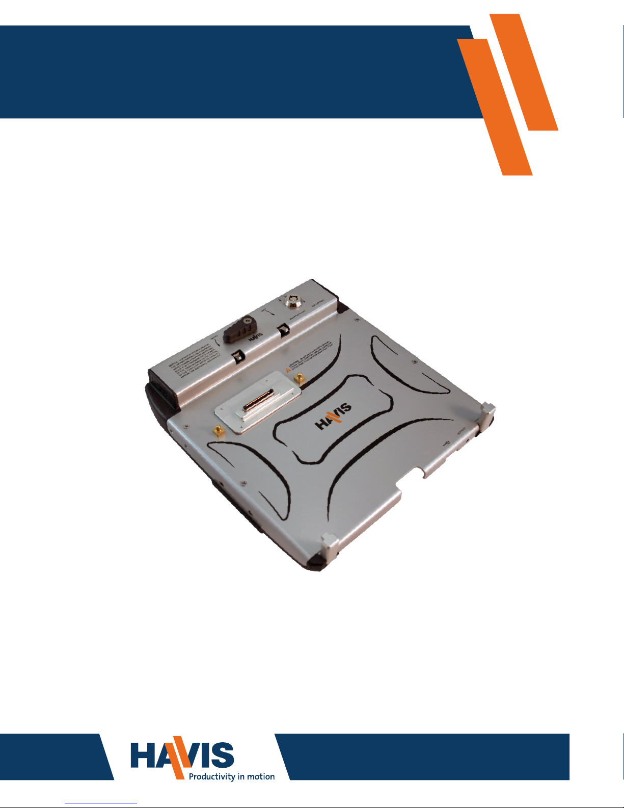
Owner’s Manual
Havis Rugged Mobile Docking Station
For Panasonic CF-19 Toughbook
www.havis.com
1-800-524-9900
DS-PAN-211
DS-PAN-211-2
DS-PAN-212
DS-PAN-212-2
DS-PAN-213 DS-PAN-214
DS-PAN-214-2
DS-PAN-221
DS-PAN-221-2
DS-PAN-210 Series/220 Series
• FOR PROPER SYSTEM FUNCTION, SPECIFIC DOCKING STATION MODELS MUST BE
USED WITH SPECIFIC CF-19 MARK LEVEL COMPUTER MODELS.
(PLEASE VISIT WWW.HAVIS.COM/CF19 FOR CURRENT COMPATIBILITY INFORMATION)
DS-PAN-211
DS-PAN-211-2
DS-PAN-212
DS-PAN-212-2
DS-PAN-213 DS-PAN-214
DS-PAN-214-2
DS-PAN-221
DS-PAN-221-2
Before Beginning
(Original Instructions)
2 11
• NEVER STOW OR MOUNT THE DOCKING STATION DIRECTLY IN A VEHICLE
AIRBAG DEPLOYMENT ZONE.
• DO NOT USE COMPUTER WHILE DRIVING.
• READ ALL INSTRUCTIONS THOROUGHLY BEFORE BEGINNING INSTALLATION.
• DO NOT MATE COMPUTER TO DOCKING STATION UNLESS COMPUTER’S DOCKING
CONNECTOR ACCESS DOOR IS FULLY OPEN OR DAMAGE MAY RESULT.
Havis is pleased to provide this Owner’s Manual to aid in the proper installation
and use of the DS-PAN-210 Series/220 Series Docking Station for the Panasonic
CF-19 laptop computer.
For questions regarding the set-up of your DS-PAN-210 Series/220 Series
Docking Station, please contact Havis at 1-800-524-9900 or visit www.havis.com
for additional product support and information.
This Owner’s Manual applies to the following Part Numbers:
Installation of Screen Stiffener (DS-DA-405 - Optional)
Installation of USB Laptop Lighting (DS-DA-101 - Optional)
1) Align holes in Screen Stiffener bracket with the mounting holes on the left
side of Docking Station.
2) Insert the (2) #8-32 Screws and torque to 16.0in-lbs (1.8Nm) ± 10%.
3) Loosen Adjustment Knob to set the desired position of the LCD and tighten
Adjustment Knob to secure position.
1) Remove Screen Stiffener Clip from Upper Bracket and spread open tabs to
allow insertion of USB Laptop Light cable into accessory retaining hole.
2) Snap USB Powered Light into Screen Stiffener Clip so that top surface of Bulb
is ush with bottom surface of Clip and insert assembly into Upper Bracket.
3) Work tabs outward so that retaining features on both sides of Clip t through
positioning window on the Screen Stiffener Upper Bracket.
4) Plug the Laptop Lighting USB connector into one of the USB ports in your
computer or Docking Station.
Adjustment knob
#8-32 Screws
NOTE: A Screen Stiffener (DS-DA-405) is required to install Laptop Lighting (DS-DA-101) to Docking Station.
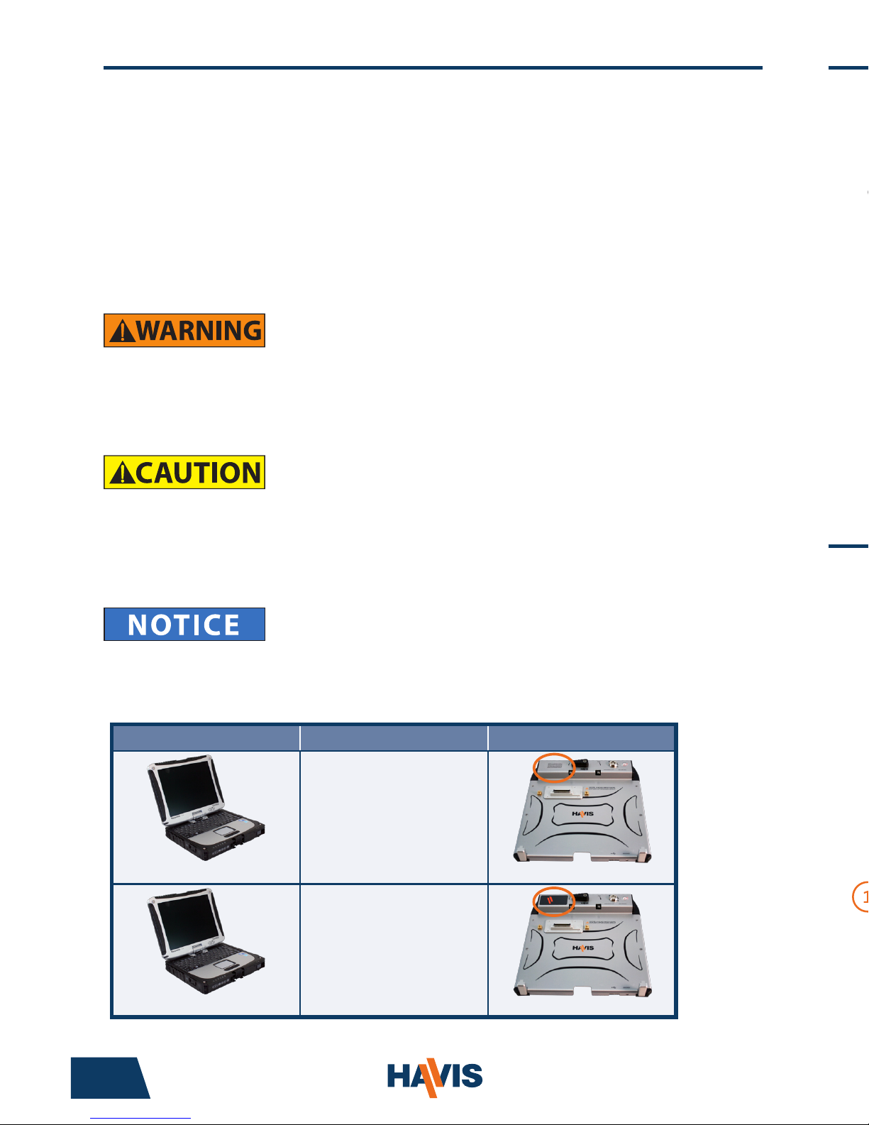
COMPUTER MARK LEVEL DOCKING STATION IDENTIFICATION
MARK 4 & HIGHER
DS-PAN-210 SERIES
• DS-PAN-211
• DS-PAN-211-2
• DS-PAN-212
• DS-PAN-212-2
• DS-PAN-214
• DS-PAN-214-2
‘NOTICE’ in upper left corner
ALL MARK LEVELS
DS-PAN-220 SERIES
• DS-PAN-221
• DS-PAN-221-2
LABEL in upper left corner
www.havis.com • 1-800-524-9900
Table of Contents
Specications
Parts Included
Port Replication Capability
Installation
Cable Management
Operation - Docking
Operation - Undocking
3
4
4
5
6
8
9
Specications
Power Supply Input 15.6V DC-In
Dimensions* 10.9” ( 27.7 cm) W x 11.1” ( 28.1 cm ) D x 3.25” ( 8.2 cm ) H
Weight* 3.8 lbs ( 1.7 kg )
Operating Environment 5° C to 35° C ( 41° F to 95°F )
Storage Environment -20° C to 60° C ( -4° F to 140° F )
* DS-PAN-211
• Do not place metal objects or containers of liquid on top of the Docking Station
• If a malfunction occurs, immediately unplug the Power Supply and remove the laptop
• Use only the specied Power Supply with this Docking Station (Recommended Part # LPS-101)
• Do not store the Docking Station where water, moisture, steam, dust, etc. are present
• Do not connect cables into ports other than what they are specied for
• Do not leave the Docking Station in a high temperature environment (greater than 60°C, 140°F)
for a long period of time
Precautions
DECLARATION OF CONFORMITY FOR CE MARKING
Havis, Inc. declares that their DS-PAN-210 SERIES/DS-PAN-220 DOCKING STATIONS:
Are classied within the following EU Directives:
EU Electromagnetic Compatibility Directive 2004/108/EC
And further conform with the following EU Harmonized Standards:
EN 55022 (2006) + A1 2007, EN 55024 (1998) + A2: 2003
EN 50498: 2010
Clause 7.1 Broadband Radiated Disturbances - Quasi-Peak
Clause 7.2 Narrowband Radiated Disturbances - Average
Clause 7.3 Conducted Radiated Disturbances - Severity Level 2
Dated: August 19, 2010
Position of signatory: Chief Information Officer / Chief Financial Officer
Name of signatory: Steve Ferraro
Signed:

Parts Included
4 9
Lock
Latch Handle
Dock Indicator LED
Front Hooks
Front USB Port
Docking Connector
Docking Station
Mounting Bracket
Hardware Kit
This Hardware Kit includes:
1. Zip Ties (4)
2. Keys (2)
3. 1/4”-20 x 5/8” long
Button Head Screws (3)
4. 1/4”-20 x 3/8” long
Pan Head Screws (4)
Tools required for installation:
• #3 Phillips Drive
(For attaching Mounting Bracket
to Docking Station with Pan Head
1/4”-20 Screws)
• 5/32” Hex Drive
(For attaching Mounting Bracket
to Motion Device with Button Head
1/4”-20 Screws)
Port Replication Capability
Ethernet
RJ45
Headphone
Microphone
USB 2.0 Serial Serial VGA
Power Input
Optional Dual
Antennas
5) For theft deterrence, secure computer by locking Docking Station with
supplied key (Hardware Kit Item 2).
6) Power on computer. The Dock Indicator LED will light up green to indicate
proper system function.
Operation - Docking (continued)
Operation - Undocking
1) If previously locked, unlock Docking Station using supplied key.
2) Rotate Latch Handle counter-clockwise to the “UNDOCK” position.
3) Once unlatched grab both sides of computer and carefully lift out of
Docking Station, rear end rst.
GREEN: Computer docked, all ports ready for use.
ORANGE: USB and LAN ports are not functioning.
RED: Computer is not supported or a connection is not made.
RED (Blinking): Firmware error has occurred.
NOT LIT: Computer is not installed, is turned off, or in standby or sleep mode.
 Loading...