

Page 1

TOOLS REQUIRED:
Phillips Screw Driver Standard Socket set T-20 Torx Bit
Metric Socket set Wire Cutters Wire Crimping tool
HARDWARE:
QTY DESCRIPTION PART#
1 Front hump bracket CM008109
1 Rear mount bracket CM004239
1 Driver side trim panel CM008120
1 Passenger side trim panel CM008121
2 12 volt socket CM216560
1 Rear conduit cover CM007945
2 Hardware plug 7/8” CM86430
2 Speed nuts GSM30199
4 1/4" Flat washer GSM31005
2 1/4" x 3/4" Machine bolt GSM33001
6 #8-18 x 1/4" Screw GSM33178
2 6mm x 20mm machine bolt GSM33711
2 #10 x 3/4" Machine screw GSM34170
1 USB extension cable GSM70141
INSTALLATION INSTRUCTIONS C-VS-1900-INUT-PM
2013-2017 FORD INTERCEPTOR UTILITY
Fits Standard Interior and Optional Upgrade (Code 65U)
Vehicle specific console
19” inches of equipment mounting space and mount for
Brother Pocket Jet Printer
Always!
Read all instructions before installing any Havis, Inc. products.
Check for obstructions (Wires, brake lines, fuel tank, etc.) before drilling any holes!
Use hardware provided with install kit
C-VS-1900-INUT-PM _INST_7-17
Page 2

CM008120
Driver side trim panel
CM008121
C-VS-1900-INUT-PM
CM008121
Passenger side trim panel
CM008109
Front hump bracket
CM007945
Rear conduit cover
CM008105
Main console housing
CM216560
12 volt sockets
Note:
Some photos may show other Interceptor Utility console parts.
These photos are used for reference only.
C-VS-1900-INUT-PM _INST_7-17
Page 3
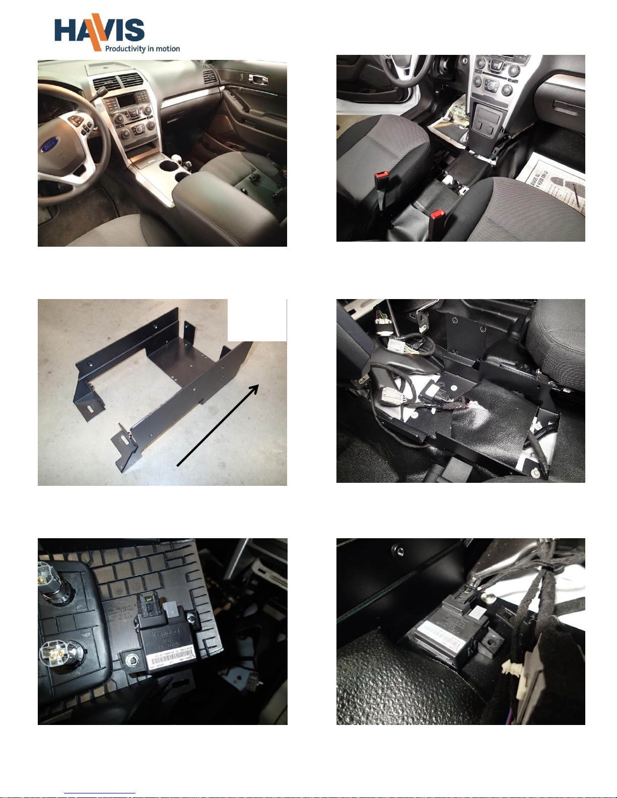
View of center console included with OEM
optional Interior upgrade 65U.
Mount sensor inside console as desired.
(for 2013 -2015 vehicles only)
Remove sensor from back of center lower dash trim.
Note: This sensor is not located on this trim panel on
2016+ vehicles. Relocation is not required.
Remove OEM tunnel plate and lower dash trim
included with Standard Interceptor Utility or center
console included with optional Interior upgrade.
Carefully place and bolt front hump bracket to floor
with previously removed OEM floor bolts. Wire
harnesses go on top of bracket.
Front hump bracket CM008109
Front of
vehicle
C-VS-1900-INUT-PM _INST_7-17
Page 4

Attach side trim panel to console housing with two (2)
8 x 3/8” Torx screws and one (1) #10 x 3/4´sheet metal
screw to lower dash.
Remove side trim panel and place supplied speed
nut onto drilled location. This provides a sturdy
mount for trim panel screw.
Attach rear bracket to existing OEM mounting
flanges with 6mm x 20mm hex bolts.
Temporarily attach side trim to console with
8 x 3/8” Torx screws and drill 1/8” hole into plastic
dash panel located behind forward hole.
Place console housing between seats and attach
sides to floor brackets with 1/4” x 3/4" Hex bolts
and flat washers.
Sensor can be mounted on the underside of the rear
mount bracket for the Interior upgrade 65U.
Harness may not be long enough for standard Utility.
Front of
vehicle
C-VS-1900-INUT-PM _INST_7-17
Page 5

Repeat process for passenger side
C-VS-1900-INUT-PM with C-CUP-2-I and
C-AP-0325
Basic console installation complete. Run wiring
and mount accessories as needed.
Insert printer assembly into the console by gently
placing it into the console from the bottom first
and pressing into place.
Snap in OEM Aux panel
Note: This panel is reused from the OEM dash
section previously removed.
If vehicle includes optional OEM conduit, remove the
rear knockout and attach the supplied rear adaptor
to rear end of console with 8-18x1/4 PFHMS. Bolt
adaptor to conduit with OEM conduit hardware.
C-VS-1900-INUT-PM _INST_7-17
 Loading...