

Page 1

fJ)
HAVERLAND
ACUMULADOR
STATIC
ACCUMULATEUR
MANUAL DE INSTALACION Y USUARIO
MANUAL DE INSTALA<;AO E UTILIZA<;AO
INSTALLATION AND USER'S MANUAL
MANUEL D'INSTALLATION ET DE L'USAGER
MODELOS / MOD
ELS
AE-08
AE-12
AE-16
AE-20
AE-24
AE-28
AE-32
~/
MODELES
ESTATICO
STORAGE
HEATER
STATIQUE
Serie
Sette
EXPLA-FLAT
Serie
MARSAN INDUSTRIAL, S.A. se rese rva hacer cualquier modificaci6n sin previo aviso.
MARSAN INDU STRI AL, LTD reserve the right to make modifications without notice.
MARSAN INDUSTRIAL,S.A. se reserve Ie droit de realiser
EXTRAPLANA
EXTRAPLANA
Series
EXTRAPLA
TE
Crta. San Martin de Valdeiglesias, Km 2,2
28925 ALCORCON (MADRID)
nimpo
rte quelle modification sans averti ssement prealable.
AENOR
lSI
Producto
Certi
fica
do
MARSAN INDUSTRIAL, S.A.
34 91 642
Tel.:
Fax: 34 91 619
7020
1950
06/03
Page 2

MANUAL DE USUARIO
IMPORT
•
OLORES,
•
dentr
aparato no deberia ca usar les iones. Se debera t
las cercanias del aparato, para asegurar que no se produ zcan contactos proLongados con
• SU
PRIM
•
como
temp eratu ra.
• A medida que el
humo de tabaco, particulas en suspension, poluci6n atrnosferica
plasticos.
NO
FUNCIONAMIENTO
IMPORTANTE
El acumulador consta de
cstudiada. En el periodo de Tarifa
mando de carga (ver capitulo C
Al final de la
refractario esta en el maximo de acumulaci6n de
EI cal or emitido por eLacumuLador debe ser suficiente para satisfacer las nec esidades de calefac ci6n de La estancia.
A medid a que el dia avanza, el calor se va transfiriendo paulatina
empieza a disminuir.
ANTE:
DURANTE
LAS
SUPERFICIES
o de Las es pecificac iones de las n
ACUMULADOR
ERA
MUY
LAS
por
PRIMERAS
Lo
conviene prestar atenci6n a
DEL
ES
REVISI6N
DEL
IMPORTANTE:
PUESTAS
ACUMULADOR
orm
MUY
PESADO.
ESPECIALISTA.
EN
La
ventiLaci6n en
PUEDEN
Los
primeros dias de funcionamiento.
ESTAR
MUY
as de seguridad en calefacc i6n ele
omar
precauciones en personas ancia nas, enfermas y nifi os que no esten vigilados en
FUNCIONAMIENTO
Por seguridad,
NO
INTENTE
EL
APARATO
CALIENTES
ctr
ica, por 10 tanto un contacto mom entaneo con el
eL
acu mulador.
DESPLAZAR
PUEDE
. Las temperaturas su
EL
ACUMULADOR
Si no esta confonn e con su ubicaci6n , por favo r avise a su instalador.
EMITIR
Cuando no se pueda aLcanzar la temperatura adec uada en [a habitaci6n (p.e. 20°C) normalmente es
consecuencia de haber montado un acumulador de potencia inferior a La que deb erfa haberse instalado, para al
CUBRA
tiernpo trans
NI
OBSTRUYA
curr
e pueden osc urecerse las paredes cercanas al acumulador, si existe en el ambi ente particulas de
0 si la pintu ra de las paredes presentan alto contenido en materiales
LAS
SUPERFICIES
DEL
APARA
TO.
DE
SCRIPCI6N
1. Limitador terrnico.
2.
Bimet
DEL
al.
ACUMULADOR
3. Caja de Mand os.
4.
Tr
ampilla salida de aire caliente
5. Rejilla salida aire caliente.
6. Aislami ento.
7. En volvente exteri or.
8. Resistencia a
cumul
aci6n.
9. Bloqu e de acumulaci6n.
10. Pean a.
DEL
ACUMULADOR
: Estas instru cciones de montaje deben ser lefda s cuidadosamente y guardadas para futuras con sult as.
LadrilL
os de un material r
Noctum
ARGA
), liberando despues el calor acumulado durante el dia.
car
ga (manana), el ca lor emi tido por el acumulador es, en su mayorfa , por radiaci6n. Esto es debido a que el material
efr
actario de altas prestaciones aislados por una carnara de aire cuida
a, las resi sten cias aportan al materi al refractario el calor previamente seJeccionado por el
caL
or.
ment
e por convecci6n a la habitaci6n y la cantidad de calor liberada
HUMOS
perf
iciaLes es tan
SIN
canzar
Fig. I
dosa
Y
UNA
dicha
mente
ULACI6N
ACUM
EL
control de
graduable entre el MI N. y el MAX. A may or aproximaci6n del
La acumulaci6n maxima se ob tiene con el mando en la posici6n
necesaria para temperatura s ex teriores muy bajas. La acumulaci6n aconseja ble para tener un
variar el mando de carga
alcanzado la temperatura deseada. Si despues de la posici6n elegida del mando, la t
(CARGA)
La
acumulaci6n se efecnia mediante el mando de carga situado en la parte superior derech a (fig. 1) de forma total
MAX
entr
e el
MIN
. y el
., mayor temperatura seleccionada y
MAX
. en un tiempo de 8 horas. La acumulac i6n ma xima solo sera
MAX
.. EI ajuste debe realizar se poco a poco,
con
compr
emp
eratura de la habitaci6n no es la deseada,
mayor
carga.
fort deseado, se ob tiene haciendo
obando aJ dia siguiente, si se ha
mente
mover el mand o.
CALEFACCl6N
EI acumulador aporta el calor al local autornaticamente dependiend o de la acumulaci6n deseada. Con el
en eI
modelo
accionando la trarnpilla de salida de aire. Con eI mand o situado en la posici6n del
se e limina solarn
calor en la may oria de las ocasiones y por tanto no es necesario alterar
de
calo
r superior en el periodo de "tarde", entonces se aj usta el mando a la po sici6n hac ia el MA X., con ella se logra ab rir la
(DESCARGA )
AE-08,
que
lleva
salida
automatica
ente
por radi aci6n y co nvecci6n a traves de la pa redes del aparato. Esto,
) (fig. J), situado en la parte superio r, se pu ede regul ar la descarga del aparato,
La
mand
o de descarga (excepto
MrN
., el regul ador perrnanecera cerrado, y el calor
por
sf solo, pued e suministrar suficiente
posicion del mando. Sin em bargo, si se necesita un aporte
trampilla de regulaci6n y se permite una salida mas rapid a de aire ca liente. Cuanto mas aprox imado este el mando de la descarga en
la posici6n MAX., mas rapida es la descarga
DA
TOS
TECNlCOS
MODELO AE-08
POTENCIA (W)
VOLTAJE
CARGA NOMINAL (KWh) TIEMPO 6,4 9,6 12,8
CARGA 8 h
(V
-)
N"DE RESISTENCIAS 800 W I
N° DE RESISTENC IAS 1200 W
N" DE REFRACTARIOS AE-228
N" DE REFRACT ARlOS AE-342
PESO SIN REFRACT ARIOS (KG.)
PESO CON REFRACTARIO S (KG.) 38 56
I ALTO
DIMEN SIONES
(nun) I LARGO
!FO
NDO
deL
acumuL
ador
y por tanto, el acumulador se enfriara antes.
AE-12 AE-16 AE-20
800
230 230 230 230
-- --
4
----
to
715 715 7 15 715 7 15 715 715
320 463 577
160
1200
-----
1 ---- I
----
-
4
16 20
160
1600 2000 2400 2800 3200
2
8
-- --
77
160 160 160
16
I
4 12
4
23
9 1 111 125 145
691
AE-24 AE-28 AE-32
230 230
19,2 22,4
3
2 4
---- I
---- 4
8
27 29
805
9 19
160 160
230
25,6
-----
16
--- -
33
1033
Page 3

LIMPIEZA
DEL
ACU
MULADOR
Para su limpieza superficial usese una gam uza de polvo. Durante los meses de verano, cuando el acumulador no se usa y las
superficies esten frias, puede usarse un trapo humedo. No utilizar, en ningun caso, produ ctos de limpieza abrasivo s, y en general
ningun producto con elementos de suspension que pueda ensuciar el entorno.
ELIMINACI6N
ONOC
ARGA:
DE
PEQU
ENAS ANOMALIAS
Comprobar posicio n del rnando de carga.
Comprobar conexion a la red.
Comprobar si el limitador terrnico de seguridad ha desconectado. Mirar el apartado
Si el aparato no carga por ninguno de los motivos anteriores, contacte con un Servicio Tecnico Autorizado (S.A.T.).
o NO ABRE LA TRAMPIL LA
La trampilla de salida de aire esta dotada de un mecanismo que impide su apertura durante los periodos de carga y las
primeras horas de descarga. Este funcionarniento nos perrnite conseguir un reparto uniforme del calor a
dfa y evitar perdidas durante el perfodo de carga. .
Si la trarnpilla no se abriera al final del periodo de la descarga en la posicion del mando en MAX ., contacte con un
Servicio Tecnico Autorizado.
GARANTIA
LA
INSTRUCCIONES,
DEL
ACUMULADOR
DESCRIP
, NO CUBRI RA
CI6N
DET
ALLAD
LOS
DANOS
CAUSA DOS
A ACUMULADOR
POR
ESTAnco
Limitador termico de seguridad.
10
largo del
NO
SEGUIR
TODAS
EST
As
MANUAL DE INSTALACION
LA
INSTALACI6N
DEBERA
ESTE
A,JUSTARSE A LAS
APARATO
imprescindible
FIRME
Y NIVELADA. E
NOTAS IMPORTANTES PARA LA INSTALACION:
NO CUBRIR NI SITUAR OBJETOS EN CONTACTO CON EL ACUMULADOR.
Conservar 25 em. mfnimo de distancia en la parte superior a cualquier colgadura 0 estante.
Conservar 10 em. minima de espacio libre a ambos lados del acumulador.
Conservar
Para mayor rendimiento del acumulador se dejara una separacion a la pared de 25 mm. minimo.
Despues de haber vuelto a instalar el aparato en otro lugar, se pondra en funcionamiento durante el primer periodo de
carga bajo el control del instalador.
Asegiirese de que el rodapie no es mayor de 25 mm de grosor.
Si quiere dejar fuera de servicio el aparato, desconectelo de la
EI tiempo de carga nominal de estos acumuladores es de 8 horas, y debe ser controlada por un dispositivo
programador.
Desconectar el aparato antes de realizar cualquier operac ion en su interior.
NO ABRIR EL APARATO ESTANDO ESTE CARGA DO (CALIENTE).
Este aparato debera estar instalado, de forma que los interruptores y otros dispositivos de mando, no pueden ser
toeados por una persona que este en la
que
DE
ESTE
PESA
se
FUE
APARATO
DISPOSI
MUCRO
. Con
FIRMEMENTE
vitar
superficies irregul ares del tipo alfomb
CIONE
objeto
A LA
DEBE
S NA
IOem. minimo de distancia entre el aparato y materiales combustible, tales-como cortinas y muebles.
bafiera 0 ducha.
SER EFECTUADA
CIONALES VIGENTES
de m
antener
PARED y que
la e
stabilidad
las p
ras 0 det
instalacion.
I IMIT
Ap
POR
UN
SOBRE
y de
ata
s se
hallen
erminadas baldo
OR TfR MICO
INSTALADOR
INSTALACIONES ELEC
garantizar
montadas
la seguridad
sobre
sas.
CUALIFICADO,
TRI
CAS.
futur
a, es
UNA
SUPERFICIE
Y
3
Page 4

OPERA
1.-
1.1 Desembale el acumulador quitando
1.2 Para
1.3 Desplace
2.-
2.1 Retir e el panel interior sacando los
2.2 Con
3.-
3.1 Retire el acondicionador del cart6n
ClONES
DESMONTAJE
las pieza s protectora s inter iores.
PARA
DEL
LA
INSTALACION
MUEBLE
quitar el frente saque los
tornillos de la parte
el frente hacia arriba
basta desencajarlo de techo de
apa rato.
DESMONTAJE
tornillos que tiene en los bordes
desencajandol os del muebl e.
el panel interior sale el
aislarniento termico al estar unido
a este. Depo sitelo de tal rnanera
que no pueda dafiarse.
DESMONTAJE
que sujeta las resistencias y
extraiga de el las peanas del
apara to, los separadores de pared y
las bolsas de accesorios.
inf
erior.
DEL MUEBL E
DEL
MUEBLE
distancias que se describe en el
diagrama adjunto. Taladre la
pared , coloque los tacos y atorni lle
co n los tornill os el soporte a la
pared (material suministrado).
"A"
~
~
o 0 0 0 0
~
MOD. A
AE-08 207
AE-12 285
AE-16 399
AE-20 513 256,5 640
AE-24 627 313,5
AE-28 777 388,5
AE-32 855
Cotas en mm
5.- FIJACION DEL AC UMULADOR
5.1 Ponga las peanas al aparato en la
5.2 Afloje (no los quite) los 4 tornillo s
'
'
~
~
&??W~
SUELO / SOLD / FLOOR / SOL
B
parte inferior (segun d
adjunto)
cabeza hexagonal que se
encuentran en la bolsa de
accesor ios.
situados en la trasera, 2 en cada la
teral (IMPORTANTE: AFLO JE
LOS TORNILLOS INTERIORES ,
NO LOS EXTERIORES).
con los 4 torni llos de
c
260 640
iagra
H
640
640
640
640
640
ma
]
' . ~
C
ORR
EC TO
6.-
ESQUEMA
Este acumulador necesita una buena
instalaci6n de toma de ti
Descon ecte siempre el cable de
alirnentacion antes de acced er a los
componentes y conex iones electrica s.
r - -
-----
1 ' 1
I I j I
~t---4---1
N . I L
7.-
COLOCACION
7.l . Encaje .los refractario s trasero s
por detras de las resistencias,
abatiendo estas hacia de.lante.
Primero se deben co.locar los
bloques laterales y por ultimo los
centr ales. En el caso del modele
AE-20 los ladrill os grandes (AE -
342) se colocan en el lade
izqui erd o y en el mod ele AE-28
los ladrillos grandes se colocan en
el medio .
7.2 Coloque los r
asegurandose de que apoy an
p
erf
resistencias estan bien colocadas
en el canal del aire .
7.3 Cornprobar que el mecanismo de
apertura de la trarnpilla funciona
libremente, girando a izquierda y
derecha el mando de descarga.
ELECTRICO
-
.,
~
ectarnente y que las
e2;
err
a.
ACUMULADORES ESTATICOS
ESQUEMA ELECTRI CO
3
AE-08. AE-12, AE-16. AE-20.
AE-24, AE·28, AE-32
1 RESISTENCIA
2 LlM ITADOR TERMICO
3 TERMOSTATO DE CARGA
4 REGLETA CONE XION
T
REFRACTARIOS
efr
actarios frontales
4.- FIJACION
PARED
4.1 Es importante que se escoja el
metodo de fijacion apropiado para
el material de la pared a la que
deba fi
Algunos materia les modernos de
construccion intern a son de muy
baja densidad y requieren
dispositivos de fijaci6n
especializados para prop orcionar
una instalacion segura y
4.2 Posicione el soporte en la pared y
marque los agu
SOPORTE
jar
se el acumu lador.
jer
4
A LA
fU
a.
os con las
5.3 Encaje el mueble en el soporte por
las dos ranuras de la parte trasera.
J
Page 5

8.-
MONTAJE
8.1
Conec
por el retenedor (utilizar siernpre cable resistente al
aparato). Conectar a la regleta y al tornillo de toma de tierra. Asegiirese de que las con exiones
torni
8.2 Intercalar entre
8.3 Vuelv a a colocar el panel interior con el aislante,
LOS AI
FINAL
tar a la toma de coniente prevista para la
11
0 del retenedor.
el aparato y la instalacion electrica un interruptor de corte.
SLANTES
. Ensamble el mueble.
TARIFA NOCTURNA
calor
tipo H
OS
RR-F
ASEGUR
.A.NDOSE DE
. Conexionar el cable de alimcntac ion intr odu ciend olo
0
HOS
QUE
VV-F. No dejar
esran bien apretadas. Apriete el
NO QU
EDE
exceso
del misrno dentro del
NINGUNA
FISURA ENTRE
9.- LIMI
rojo), corta el funcio namiento del acurnulador en ca so de un
Para restab lece r el limitador terrnico:
2. Qu itar los tornillos situad os en la parte inferior del frontal del acumulado r.
3. Tira r hacia delante el panel frontal hasta que quede libre del fo
4. Pulsar el boron rojo del limi tador.
5. Colocar el panel frontal exterio r, realizando las operaciones inversas a los pasos 3 y 2.
6. Restablecer la toma de corrie nte .
Al sustituir cualquier
original. En el caso de que el rnisrno acumulador se instale por seg unda vez, 6 sucesivas, las partes dafiadas
aislantes deberan ser sustituidas por partes identicas.
El acumulado r no calie nta nada.
1. Autornatico e
2.
3. Regulador de carga defectuoso, Soluci6n : Sustituir.
4. Limitador terrnico defectuo so, Sustituir.
TADOR
Ol'
medio de un limitad or ter rnico de rearme manual, situado en la parte interna superior lado derecho (dispos itivo con un boron
P
1. Asegurarse que el acumulad or este desconectado de la tom a de co rriente.
que se suelte la pestana que
10.-
MAN
11.- OBS ERVA
Com
TERMICO
DE SEGURIDAD
exceso
de tem peratura.
nda
del acumulador. Empujar hacia
ani
ba el panel frontal, para
10 retiene.
TEN
IMIENTO
component
CIO
NES
xtem
o de sconectado . Solucio n: Conec tarlo.
probar limi tador terrnico, Soluci6n : En caso de que se haya de sconectado, rearmarlo (se expl ica en el a
e, debe tenerse mucho
EN CASO DE
ANOMALlAS
cuidado
en colocar los cables, los aislantes y el bulb o del mismo modo que el
0 deterioradas de los
par
tado n''. 9)
j
5
Page 6

IMPORT
ANTE
MANUAL DE
UTILIZACAO
:
DURANTE
•
E
ODORES, PELO
• ESTE
fixe
firmementeaparede 0 suporte
•
Com 0 transcurso
existem
conteudo alto de
NAO
TAPE
AS
PRlMEIRAS
APARELHO
particulas
materiais
NEM
OBSTRUA
QUE
SE
RECOMENDA
PESA
do tempo se 0
VEZES
MUlTO.
de
parede
QUE
Com 0
ambiente
em suspensao (poeira no
plasticos as
AS
SUPERFICIES
paredes
PUSER
EM
FUNCIONAMENTO, 0 APARELHO
QUE 0 COMPARTIMENTO
objectivo
e os
de
manter a estabilidade
pes
sejam
montados
onde
einstalado 0
ar),
poluicao atmosferica ou a
proximas
DO
APARELHO
sobre
ao
acumulador
.
DESCRI <;AO DO ACUMULA
I. Limitador terrnico
2.
3.
4.
Resistencia bimetal
Painel de control
Registo de saida de ar quente
ESTEJA
BEM
do
uma
superffcie
acumulador
podem
DOR
VENTILADO.
acumulador
firmee nivelada.
eurn
ambiente
pintura
escurecer
PODE
, e
irnprescindivel
das
paredes
Jigeiramente.
EMITIR
de fumadores, se
MIN. DESCA.RGA
5. Grelha de saida de ar quente
6. Isolam ent o
7. Carcaca exterior
8.
Resistencia
9. Bloco de acumula cao de ca lor
Suportes (Pes)
FUNCIONAMENTO
IMPORTANTE:
Estas instrucoes de montagem devem ser lidas cuidadosa mente e consideram que as necessidades de aquecime nto
DO
ACUMULADOR
10.
do compartimento forarn calculadas correctamente.
o acumulador e consti tufdo por bloco s de urn material refractario de alta performance , isolad os por uma carnara de ar
cuidadosamente estudada. No perfodo da tarifa nocturna, as resis tenc ias transmitem aos blocos refractarios
seleccionado pelo term ostato de carga (ver capitulo CARG A), libertand o estes depois
No final da ca rga (rnanha),
0 calor emitido pelo acumulado r e na sua rnaiori a, por radiacao. Isto deve-se ao facto de os refractarios
0 calor acumulado, durante 0 dia.
0 calor previarnen te
estarem no maximo da sua carga.
com
Este calo r ernitido por radiacao deve ser suficiente para satisfazer as necessidades de aquecime nto do
A medida que 0 dia avanca, 0 calor vai-se transferindo lentamente por co nvecc ao ao
comp
artim ent o e a quantidade de calo r libertada
partimento.
corneca a diminuir.
FUMOS
que
apresenta
Fig. 1
se
urn
MI N. CA RGA
ACUMULAC
Ao (C
ARGA)
o controlo da acurnulacao faz-se atraves do term ostato de car ga (Fig. 1) de form a totalmente gradual entre 0 Min . E o Max.. Quanto
emp
rnaior for a proximid ade do Ma x, rnaior a a t
A acumulacao maxim a, obtern-se co m
0 termostato no Max. a carregar num p
necessaria para temperaturas exteriores muito baixas em relacao
A acumulacao aconselhavel para obter
0 conforto desejado, obtem-se faze ndo variar 0 regulador entre 0 M in e 0 Max. 0 ajuste dev e
eratura seleccionada e rnaior e a carga termica.
eri
odo de 8 horas. A acurnulacao maxim a so sera
it temperatura ambiente do local.
realizar-se pouco a pouco, verificando no dia seguinte se ja se alcanco u a temperatura desejada.
AOUE
ClM
ENTO CDESCARGA)
o acumulador transmit e
descarga (Fig . I) podemos accionar
DURANTE
FECHADO
AS
INDEPENDENTEM
Se nas ultimas horas da tarde se deseja aumentar a saida de calor. deve-se colocar
(Excepto
no
modelo
Quanto mais pr6ximo esuver 0 regulador da desc arga da posicao Max., mais rapida ea descarga do acumulador e
rapid amente esgotara
DADOS
POTENCIA (W)
TENS AO (V - )
ENERGIA ACUMUL ADA (KWh ) EM 8 h
DECARG
N° DE RESISTENC1AS 800 W
N" DE RESISTEN CIAS 1200 W
N" DE REFRACTARIOS AE-228 4
N" DE REFRACTARIOS AE-342
PESO SEM REFRACTA RIOS (KG.) 10
PESO COM REFRACTARIOS (KG.)
D1MENSOES (m
TECNICOS
A
0 calor ao co mpartimento automatica mcn te dep end endo da acu mulacao realizada. Com 0 regulador de
0 registo de descarga para regul ar a conveccao desejada, tendo no entanto em con ta que:
PRIMEIRAS
AE-08,
0 calor acumulado.
MODELO
I ALTUR A
m)
[L
que
ARGU RA
HORAS DO
ENTE
DA
por
ser
automatica a saida
PERIODO
POSI<;AO
AE-08 AE· J2 AE-16 AE-20 AE-24
800
230 230 230 230
6,4
1
-- --
-
---
38 56 77 9 1
7 15 7 15 7 15 7 15 7 15 7 15
320 463 577
DE
DESCARGA
DO
REGULADOR
de calor ,
1200
9,6 12,8 t6 19,2
-- - --
I
nao
----- 8
4
16
(PELA
DE
tern
1600 2000 2400 2800
2
----
---- 4 -- --
20 23 27
MANHA
DESCARGA.
0 regulad or de descarga na posicao Max. (Fig. I).
comando
de
descarga),
I 3 2 4
I
4
69 1
) 0
REGISTO
230
-- --
12 8
I.JI
805
I PROFUNDIDADE 160 160 160 160 160
PERMANECE
port
anto, rnais
AE-28
230
22,4
I
4
29 33
125 145
919 1033
160 160
AE-32
3200
25,6
-----
715
230
16
-- --
•
Page 7

LIMPEZA DO ACUMULADOR
Para a Iimpeza superficial do
superficies estao frias,
nenhum
produto
com
acumul
ado r use-se um
pode
usar-se um pano hiimido. Nao utili zar em
elemento
s de susp
ensao
ELIMINA<;:AODE PEQUENAS ANOMALIAS
NAO
CAR
REGA
Verif
icar a pos icao do regul
Veri ficar a ligacao arede.
Verificar se 0 limit
Se 0 aparelh o continua a nao carregar, contacte um
NAO
ABRE 0 R
Este
registo esta dotado de um sistem a que impede a sua
permite-nos co
Se 0 registo nao se
tecnico autorizado.
ador
EGISTO
nseg
abre
ador
de carga .
terrnico de segu ranca desligou.
DE
DES
CARG
A
uir uma distribuicao do calor de uma f
co m 0 re
gulador
de des
car
pano
de po, Du rante os
Ver
0 capitulo
service
tecni co autorizado .
abertur
a durante as horas de ca rga e as primeiras de descarga. Este sistema
orma unif
ga na posicao Max. , durante a ultima fase da descarga, contacte um serv ice
onne
meses
de ver so, qu
nenhum
LIMITADOR TERMI
caso
produt
ao longo do dia e
ando 0 acumulad
os de
limpeza
CO DE
evit
ar p
erdas
or nao se usa e as
abra sivos e em geral
SEGURAN
durante a car
c;A
ga.
A GARANTIA DO ACUMULADOR NAO COBRE DANOS CAUSADOS POR NAO SE SEGUIREM
ESTAS INSTRU<;:OES.
DESCRICAO DETALHADA DO ACUMULADOR ESTATICO
ISOlAM
l AM
LIMiT A DO Il
ENr
:, INFt
DE
_"'OM
11
HA
_~
.....
ISO
~BQR'fS
RI DIl
rEIlMI
CQ
CORRECTAMENTE
PES
INSTALACAO
A INSTALA<;AO DEVE
ESTE APARELHO PESA MUlTO. Com 0 objectivo de
firmemente aparede 0 suporte de parede e os pes sejam montados sobre uma superficie firme e nivelada.
IMPORT
ANT
E:
oacumulador
o assentarnento co rrecto do acumulado r e imp
Manter um minima de 25c m de distancia da parte superior do
M
anter
M
anter
Nao
cobrir nem colocar objectos sobre 0
Quando se reinstalar um acumulador noutro local de verao as primeiras
instalador.
Entregue este manual de instrucoes
A instalacao
Desligar 0 aparelho da rede antes de realizar
Nun
ca abrir 0 acu mulad or
Este aparelho de vera ser instalado de f
chu veiro.
o tempo de carga
urn
urn
SER
EFECTUADA
deve
ser montado num local seco e sobre um a superficie plan a, hori zontal.
minima
de lOcm de d ist
minima
de IOcm de distancia
deve
ser realizada por pessoa l qua ilificado e de
enquanto
nomin
al do
acu
POR
UM INSTALADOR QUALIFICADO.
manter
ortante
ancia
de ambos os lados do
entre
acumulad
devera
ser cu idadosamente conservado e quando hou ver rnudanca de proprietario.
qualquer oper
este
estiver
orma
a que nao possa ser t
mulador sao 8 horas e dev e ser
a estabilidade do acumulador, e imprescindivel que se fixe
, os pes devem
aparelh
0 acumulado r e materiais cornbustfveis, tais
or.
aco
acao no seu interior.
carregado (quente).
estar
o a
acumul
rdo co m as normas em vigor.
ocado
controlado
sobre um a base f
qualqu
er objecto ou estante.
ado
r.
horas
de
carga
pOl'uma pessoa que esteja numa banhei ra ou
por urn relogio programador.
irme
como
ser
acompanhada
.
cortinas e m
s pelo
ovei
s.
7
Page 8

OPERA<;:O
1,- DES
1.1 Desem bale
1.2 Para tirar
1.3 Retire
2.- DE
INTE
I
SOL
2.1 Desap erte os par afusos que estao
2,2 Com
ES PARA A IN
MON
TAGEM DA CA
0 acumulador tirando
as peca s protector as interiores.
0 paine l in retire os
pa
raf
usos da par te inferior.
0 paine ! fazendo-o deslizar
no sentido da grelha.
SMONTAGEM
RIOR
AMI ENTO
nos rebordos e retire
interio r.
isolarnento terrnico. De be pousarse este de forma a nao danificar
E RE
FRO
0 painel interior sai 0
STALA<;:
RCA<;:
DO PAI NEL
SPECTIVO
NTA L
0 pain e!
A
isolarniento ,
3.- ACONDICIONA M
INTE
RIOR
3.1 Re tire a peca de
as resistencias, os separadores de
parede e tire os
de parafusos.
IENT
O DO
car
tao que segura
suport e s e a bolsa
AO
a parede onde vamos fixar
acurnulador (nao usar buchas de
plas tico para fi
L2 Posicio ue correctarncnte a barra de
fixac ao na parede e marque
dos furos. Faca os furos na parede
e fixe a barr a usando as buchas e
parafusos que sao for necidos no
saco.
"C"
P2
MOD. A B C
AE-08
AE-12
0
AE-16 399
AE-20 513
AE-24 627
AE-28
AE-32
Cotas em mm
5.5, I Co loq ue os pes na par
FIXA
"
207
285
777 388,5
855
<;:
AO DO A
(conforme desenho) usan do os 4
parafusos de ca beca hexagonal
fornecidos no saco.
5.2 A1iviar
parafusos situados na parte
traseira, 2 em , cada lado
(IM
POR
PARA F
NAO
OS EXTERTORES) ,
jar
0 acurnul ador). I
0 local
"A"
.- -
---
---
256,5
313.5
---
260 640
CUMULADOR
(nfio os retire ) os 4
TAN
TE:
ALIVIAR
USO
S INTERT
640
---
640
---
--- 640
--- 640
---
640
640
---
te
inferior
ORE
H
OS
S,
0
6.-
ESQU
EM A ELE
Este acum ulado r necessita de uma
instalacao co m boa ligacao
Desligu e sernpre
antes de ace der ao inte
acu mulado r.
CTRI
0 cabo de alimentacao
3
: : 2
L eJ
r - ------
I I
I I I I
N~t
---4-
7.- C
OLOCA<;:
REFR ACT ARIOS
7.1 Encaixe os refractarios traseiros
por tras das resistencias,
rebatendo-as para a fre nte.
aconselhavel colo car pri mero os
dos extremos. No caso do modelo
AE-20 os refra
(AE-3 42) sao co!ocados no lado
esquerdo e no mod elo AE-28 os
refractarios gra ndes
no centro .
7.2 Coloque os r
asseguran do-se de que estes estao
bern apoiados e qu e as
resistencias estao
no canal de ar.
7,3 Verifi car qu e
aber
girando
a esquerda e para a direita.
-
.,
---lJL
AO DOS
cta
efr
actarios fron tais
0 registro de
tura funciona Iivrernente,
0 botao de descarga para
CO
it terr a.
rior
do
ESQUEMA ELECTRI CO
AE-08, AE-12, AE-16, AE-20,
AE·24, AE-28, AE-32
1 RESISTENCIA
L1
MITAOOR TERMICO
2
3 TERMOSTATO CARGA
4 L1GADOR
T
E
rios grande s
sao colocados
bern colocadas
4,-
FIXA
<;:AO
DO SU
PA RE DE
E importa nte que se escolha 0
4,1
metodo de fixacao apro priado para
POR
TE A
5.3 Encaixe
parede usando as ranhuras na
traseira do mesrno.
0 aparelho no suporte de
8
Page 9

8.-
MONTAG
8.1 Ligar
deixar excesso do mesmo dentro do aparelho). Ligar
Iigacoes estao todas bem apertadas e apertar
8.2 Verifique que as Iigacoes (terminais) das resistencias estao bem enca ixados.
8.3 Intercalar entre
8.4 Volle a colocar 0 isolame nto frontal e 0 painel, assegurando-se que nao se encontra partid o. Recoloque 0 painel frontal.
8.5 Nunca instale
9.- LlMITADOR TERMICO DE S
Por meio de urn lim itador termico de rearm e manual, situado na parte interna superior, corta
caso de
Para rearrnar
l. Certifique-se de que 0 acumulador esta desligado da rede electrica.
2. Siga as instruccoes de instalocei: para retirar 0 painel frontal.
3. Carregar no botao verme lho do limitador termico.
4. Monte de novo
5. Ligar
10-
MANUTEN<;AO
Ao substituir qualquer componente, debe ter-se muito cuidado ao colocar os conductores, os isolamentos e todos os mecanismos da
mesma forma que se encontravarn originalmente. Quando urn acurnulador for reinstalado uma ou mais vezes os isolamentos
deteriorados devern substituido s por novo s identicos ,
11.- OBSERVA<;OES EM CASO DE ANOMALIAS
EM FINAL
0 cabo de alirnentacao introdu zindo-o pelo retentor (utilizar sempre cabo de ligacao tipo H05 RR-F ou
0 cabo de terra no parafuso de tomada corres pondentc. Verificar que as
0 parafuso do retentor.
0 aparelho e a instalacao electrica um interrupter de cor
0 acumulador sobre ou por baixo de uma tomada .
exce
sso de temperatura.
0 limi tador termico:
0 painel fronta l.
0 acumulador de novo a rede.
EGUR
AN<;A
te
.
0 funcionamiento do acurnulador em
HQ.5
VV-F . Nao
o acumulador nao aquece nada.
I Nao chega corrente ao acumulador. Verificar se
electrica.
2 Verificar se 0 limit ador terrnico foi activ ado , Nesse caso, rearrnar (seguindo as indicacoes do capitulo "LIMITADOR
TERMICO
3 Terrno stato de carga defeituoso. Substituir.
4 Limitador terrnico defeituoso. Subs tituir.
DE SEGURAN<;A".
0 relogio nao esta a cortar 0 circuito e se nao ha problemas
com
a alimentacao
USER'S MANUAL
IMPORTANT:
•
During
well ventilated.
•
This
•
This appliance
and fit the stands upon a firm, level surface.
• With time. the walls near the accumulator can darken if there are tobacco smoke particles in the enviro nment, or there are
particles in suspension. atmospheric pollution or if the wall paint has a high plastic content.
DO
FU N
IMPORT
have been corr ectly calculated.
the
fir
st
occa
sions the
appliance
NOT
COVER
CTIONING
ANT: These assembly instruc tions must be care fully read and it is ta
ha ve ver y
weights a lot. In order to maintain its stability and guara ntee future safety, it is vital to fix it firmly to the wa ll
OR
OBSTRUCT
OF
THE
appliance
hot
surfaces.
THE
STORAGE
is sta rted, it ma y release
ATTENTION
SURFA
HEATER
CES
OF
THE
smoke
and
smells, for which reason the room should be
APPLIANCE
DES
CRIPTI6N
I. Thermal limiter.
2. Bimeta l.
3.
Control' s panel.
4. Hot air outlet flap .
5. Hot air outlet grid.
6. Insulation.
7. Outer casing.
8. Heat storage resistance.
9. Heat storage block.
10. Stand.
OF
THE
kenfor
granted that the heating needs of the room
STORAGE
HEATER
MIN. DESCARG A
{
I)
Fig.
{
MIN. CARGA
I)
The storage heater consists of high performance refractory bricks insulated by a carefully studied air chamber. During the Nocturnal
Rate, the res istances give the refractory material the heat pre viously selected on the charge contro l (see cha pter CHARGING),
afterw ards releasing this accu mulated heat duri ng the day. At the end of the charging (morning). the heat emi tted by the storage
heater is mostly through radiatio n. Th is is due to the fact that the r
released by the storage heater must be sufficient to satisfy the heating needs of the room. As the day adva nces, the heat is gradually
transferred around the room by convection and the quantity of heat freed begins to diminish.
ef
ractory material is at th maxi mum heat storage rate. The heat
9
Page 10

HEAT STORAGE (CHARGING)
Heat storage control is carried out by means of the totally adjustab le control knob (Fig. I) between MIN . and MAX. The neaner to
MAX .. The nearer to MAX., greater is the temperature selected and greater the charging.
Maximu m heat storage is obtained with the control knob at the MAX. position in a time of 8 hours. Maximum heat stora ge will only
The
be necessary for very low outdoor temperatures and in relation to the atmospheric temperature of the room.
rec
onun
ended in order to achieve a desired comfort is that obtained by moving the control knob between MIN. and MAX. This
heat storage
adjustment must be carried out gradually, checking the next day to see whether the des ired temperature has been reached.
HEATING
mISCHARGING)
The storage heat storage gives heat to the room automatically depending upon the heat storage carried out. With the disch arge control
knob (Fig. I), the discharging of the appliance can be regulated, activating the air outlet flap door, bur always bearing in mind that:
of
During the first hours of the discharging period (in the morn ings), the flap door remains closed independently
the MAX. position .
If an increase in heat output is required during the last hours of the evening, situate tbe discharge control knob (Fig. I) at the MAX .
position (except in model AE-08, which, being the heat outlet automatic, the appliance does not a discharge control knob).
The nearer the discharge control knob is to the MAX . position, faster is the discharging of the storage heater and therefore the storage
heater cools down quicker.
TECHNI
POWER (W)
VOLTAGE
NOMINAL CHARGING (KWh) 8 h HOUR 6,4 9,6
CHARGE
W OF RESISTANCES 800 W
WOF
W OF REFRACTORY BRICKS AE-228 4
W OF REFRACTORY BRICKS AE-342
WEIGHT WITHOUT REFRACTORIES
(KG.)
WEIGHT WITH REFRACTORIES (KG.)
DIMENSIONS
CLEANING
CAL
DATA
MODEL
(V-)
RESISTANCES 1200 W
I HIGH
(rnm)
I LONG
I DEEP
OF
THE
STORAGE
HEATER
AE-08 AE-12
800 1200 1600 2000 2400
230 230 230
----
1
-- --
----
10
38 56
7 15 715 7 J5 715 7 15 715
320 463 577
160 160 160
-
1
-----
4
16
AE-16
12,8 16 19,2 22,4 25,6
2 1
----
8 4 12
----
20 23
77
AE-20
230 230 230 230
I
4
91
69 1 805 919 1033
160 160
AE-24 AE-28 AE-32
3
-- --
----
27 29 33
III
2800
2
I --- --
8 16
4
125 145
160
3200
----
715
160
4
For cleaning the surface , use a chamois leather. During the months of summer, when the storage heater is not used and heat surfaces
are co ld, a wet cloth can be used. Never use abra sive cleaning products or any product with elements in suspension that can dirt y the
environme nt.
CORRE
CTION
OF
SMALL
FAILURES
o NO CHARGE:
Check the position of the charge control knob.
Check connection to the current.
Check if the safety therm al limiter has disconnected. Look at the section Safety Thermal Limiter.
If the appliance still does not charge for the above-me ntioned reasons, contact An Autho rised Tec hnical Service .
o
THE
FLA P DOOR DOES NOT OPEN:
This flap door has a mechanism which impedes its openin g during periods of charging and the first hours of
discharging. This function allows us to achieve a uniform share of heat throughout the day and avoid loss during the
charging period.
If the flap door does not open with the discharge control knob at the MAX . positi on during the fina l phase of
discharging, conta ct an Authorised Technical Service.
THE
GUARANTEE
FOLLOWING
ALL
OF
THESE
THE
INSTRU
D
ETAILED
STORAGE
CTIONS
DES
HEATER
.
CRIPTION
DOES
NOT
OF
STATIC STORAGE
COVER
ANY
HEATER
DAMAGED
CAUSED
BY
NOT
l '
10
r
HA
R TH Q H
pp
P IN
TA
T
ATI N
Page 11

INSTALLA
TION
THE INSTALLATION MUST BE CARRIED OUT BY A QUALIFIED INSTALLER.
CARRIED OUT BY QUALIFIED PERSONNEL AND IN COMPLIANCE WITH
This appliance weighs a lot. In
and
fit
the
stand
s upon a firm , level surface. The storage
correct
The
positioning of the storage heater is
order
to maintain its stability
important
and
heater
, the
guarantee
must
be placed in a
stands
having to be on a firm base.
THE
future safety, it is vital to fix it firmly to the wall
dry
THE
INSTALLATION MUST BE
CURRENT NORMS STANDARDS.
area
and
on a l1at, horizontal surface.
IMPORT
ANTS
NOT
ES:
Keep a 25 e m. minimum distan ce fro m the
Keep a 10 em. free space at both sides of the storage heater.
Keep a 10 em. mi
DO
NOT
For the best funct ion ing of the storage heater , a 25 mm. minimum separation from the wall must be left operat ing.
Af
ter having reinstall ed the appliance in a
COVER
nimum
THE
installer durin g the first peri od of charg ing.
This instruction manual should be carefully kept and when there is a
user.
If yo u wish to leave the appliance out of service, disc
The n
omin
al charging time of these storage heaters is 8 h
Disconnect the appliance before undertakin g any internal ope ration.
Do not
open
the appliance if it is charged
Thi s appliance must be installed so
in the bath or sho wer.
INSTALLATION INSTRUCTIONS
1.- UNPACKING
THE
DEVICE
1.1 Unpack the storage heater by
r
emo
ving the inner protective
parts.
1.2 To remo ve the front, ta ke out
the screws from the
1.3 Turn the front upward s until
r
emo
ving it from the top
appliance .
2.-
INTERNAL COVER
INS
ULATION
2.I
Remove
taking out the sc rews it has at
the
device.
2.2 T he th
out with the front panel
jo ined to this, and must
dow n carefull y in such
that it is not damaged.
REMOV
the front panel by
edge
s, extra cting it from the
erm
al insu.lation
lower
AL
part .
of
the
AND
co mes
as it is
be laid
a way
upper part
distance b
STORA
etween
the appliance and combustible material, such as curtains and furn iture.
GE
HEAT
ER OR
PLACE OBJECTS
diff
erent pla ce, it must be started up under the control of an authorise d
(ver
y hot).
that
the switches and other co ntrol devices cannot be touched by anybody wh o is
3.- INTERNAL PR
3. 1 Remove the a ir conditio ne r from
the cardboard box that fastens
the resistances and take the
stands of the appliance out of it,
the wall separators and the bag
of accessor ies.
4 .-
FIXTUR
TO
THE
WALL
5
It
is im por tant that the
appro piate fasten ing device is
chosen for the mat eri al of the
wall to which the stora ge heater
is going to be fixed , S
modern internal con stru cti on
materials are of very low
thickness and r
devices which are speciaJised in
order
to give a secure and stable
installation.
6 Position the support on the wa ll
and mark the holes, make drilJ
holes in the wall and screw in
the suppo rt with the plugs and
lag
screw
accessor ies.
EPARATION
E OF
s supplied in the bag of
to any hanging object or shelf.
IN
DIRE
CT
CONTA
chan
ge of owner, it must be given to the new
onn
ect it from the install ation.
our
s and must be controJled using a timer de vice.
S
THE S UPPORT
ome
equir
e fast
enin
g
o 0 0 0
~
ff
///4'4W/07fftW$
ff
SUE
Lo I SOLO I FLOOR
MOD. A B
AE-08
AE-12
AE-16
AE-20
AE-24 627 3 13,5
AE-28
AE-32
Dimension
5.-
FIXATION
HE
ATER
5. J Put the stands
on the lower part (according to
the attached
hexa
can be found in the bag of
accessories.
5.2 Loosen (do not take out) the 4
screw
each
inside screws, no t the outside
on es).
~
5.3 Insert the device into the support
through the two grooves at the
rear part.
CT
WITH
IT.
' A'
ff////
ffi'ff#Ifl'E
/ SOL
C
207
285
399
5 13
-- -
---
---
256,5
---
-- -
---
--- 640
--- 640
777 388,5
855
s
In
mm.
OF
gonal
head
s located at the
side (important: L
-- -
260 640
THE
of
the appliance
diagram
screws which
---
STORAGE
) w ith four
back
oose
~
~
~
/
/ffg~
640
640
640
640
, 2 on
n the
O~
H
.r
t
I I
Page 12

CORRECT
6.-
ELECTRIC
This storage heater need s a
earth installation. Always dis
the
power
cabl e before access ing
~
SCHEMA
goo
conn
ect
electrical components and
connecti ons.
ELECTRIC DIAGRAM
AE-08. AE-12, AE-16. AE-20,
AE-24. AE-28. AE-32
1 RESISTANCE
2 THERMAL LIMITER
3 CHARGE THERM OSTAT
4 CONNECT ING STRIP
T
free ly, turn ing the disch arge co ntro l
left and right.
7.-
REFR
ACTORY
INST
ALLA
IMPORTANT
TION
: Meti
BLO
culou
CK
sly cle an
the refr actory block s of dust and dirt
before fitting them into the storage
heater
7.1 Insert the rear heat resi stant
blocks behind the resi
stan
ces,
pushing these forw ard. It is
d
advisable to place those at the
end s first. In the case
m
odel
AE- 20, the big brick s are
of
the
to be put on the left side and in
the model AE- 28; the big bri
are put in the m
iddle
.
cks
7.2 Position the front he at resi stant
blocks, ensuri ng that they rest
perfectly and th at the resistances
are correctly placed in the air
channel.
7.3 Che ck that the flap d
oor
openning mechanism functi ons
8.-
FINAL
ASSEMBLY
8.1 Connect the power cable introducing it into the ret
ainer
(always use power cable type HOS
RR-F
or HOS VV -F.
excess of it inside the appliance.
8.2 Insert a pow er cu t sw itch
8.3 Replace the insulation and inner panel , makin g sure that no crack is left. As
8.4 Do not install the appliance below a switch
betwe
en the appli
ance
and the electric installation.
block
.
semble
the dev ice.
8.S Make sure that the resistance connec tions are firml y fixed .
8.6
Connect
9.- SAFET Y TH
By means of the manu al resett ing therma l limiter, situated in the upper
temperature.
To reset the th
I. Ensure that the storage h
2.
Rem
3. Pull the front panel forward until the botton of the storage heater is freed . Push the front pan el upw ards, in or
flan ge ret aining it.
4. Push the red thermal limiter button.
S. R
6. Re-establish the current.
10.-
MAINTENAN
On sub stituting any co m ponent, great care must be t
original s. In the case that the storage heater is installed for a s
insulations must be r
to the connection strip and
ERMAL
LIMITER
ear
th. Check the con nections are well co nnected . Ti
inner
ermal
limiter:
eater
is disc
onne
cted from the current.
ove the screws situated in the lo
eplace
the outer front panel, carrying out the inverse operation as in steps 3 and 2.
wer
part of the fro nt of the sto
rage
CE
aken
in placing the cables, the insulati on s and the
eco
nd or success ive time, the dam aged or det eriora ted parts of the
eplace
d by identical components.
ghten
the retain er screw.
part , the storage heater is cut off in case of an e xce ss of
heater.
bulb
in the s
Nev
er leave an
der
to release the
ame
way as the
I 1.-
REMARKS
IN CASE
OF
FAILURE
The storage heater does not hear up at all.
I .
Outer
automati c disconnected.
Connected
2. Che ck thermal limiter. (In the case that it has been disc
THERM
AL
LIMITER
.
3. Faulty chargin g regul ator. Replace it.
4. Faulty th
ermal
limiter. Replace it.
12
it.
onnected
, reconne ct it. This is explained in the section SA FE
TY
Page 13

MANUEL DE
IMPORTANT
• AU
COURS
DES
ODEURS
•
CET
indispensable de le fixe r ferrnernent au rnur et que les pattes soint
•
Au
cours des ans, les murs situes pres de I'accumulateur pourraient devenir plus fen ces, si dans [
:
DES
. La piece devra,
APPAREIL
PREMIERES
pour
EST
TRES
MISES
EN
FONCTIONNEMENT,
autant, etre bien ventilee .
LOURO.
Dans Ie but de
L'USAGER
L'APPAREIL
maintenir
montees
sa stabilite et de
sur une surface f
PEUT
erme
EMETTRE
garantir
et ni
velee
la s
.
DES
FUMEES
ecur
ite future, il est
'air
ambiant il y a
des particules de furnee de tabae, partieules en suspension, pollution atrnospherique ou si la peinture des
eontenu eleve de matieres plastiques.
NE
PAS
COUVRIR
NI
OBSTRUER
LES
SURFACES
DE L 'APPAREIL.
mur
ET
s a un
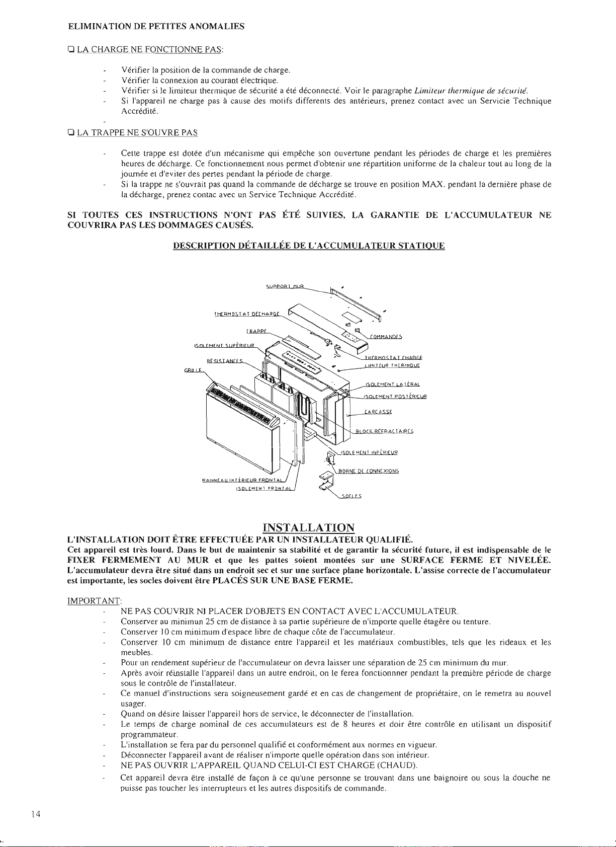
DESCRIPTI6N
I.
Limit
2.
Bim
3. BO
lte
4.
Trapp
5. Grille so rtie air cha ud.
6. Is
olem
7. En vel
8. Resistance acc umulation.
9.
Bloc dacc
10.
Socle
FONCTIONNEMENT
IMPORTANT:
besoins de chauffage de la piece.
L'ac cumulate ur
etudiee. Pedant la periode de
par la co
char
r
satisfa ire les besoins de chauffage de la piece. A me
piece
ACCUMULATION
Le
Plus on sapproac he du Max., plus on
L'accumu
ne sera necessaire que p
L'accumul ation conseillee pour o btenir le co nfort desire sobtient en faisant var ier la comma nde entre Ie
de vra se faire peu apeu. e n verifiant Ie lendemain si on a atteint la
mma
nde de charge (vo ir
ge (Ie ma rin), la chaleur ernise par lac
ef
ractaire se trou ve a so n ma
et la quantite de chale ur liberee
cont
role de
lacc
lation max ima est
DE
L'ACCUMULATEUR
Lire soigneusement ce s instru cti on s de montage;
com
prend de s briques en materiau refractaire a
Tarif
Nocturne. les resistances a pportent au materiau refr actaire la chaleur ant
chap
itre CHA RGE), et libereront ensuite ce tte ch
cumul
ateur
se fait, en grande partie, par radiation. Ceci est du a ce que Ie materiau
ximum
dacc
umulatio n de chaleur. La cha leur ernise par
surequeIejour
com
mence adiminuer.
(CHA RGE )
urnulation
seffectue
obtenue
our
des
au m
oyen
de la commande (Fig. I) de facon total
sele
cti
onne
de tempe rature, et
avec
la commande en position
temp
eratur
es e
xterieur
es tres basse s et en fonction de la
davance
haute
s prestation s, isolees par une chambre a air soigneuse ment
avance, la cha leur est tran sferee peu apeu par co nvection ala
pour
autant
MAX
. pendant une
temp
eratur
DE L'
ACCUMULA
eur thennique.
etal.
de corruna
e sortie d 'air chaud
en t.
oppe exte
.
on considere
, plus de charge.
e desiree.
ndes
rieu re.
umulatio n.
aleur
accumulee pendant Ia journee . A la fin de la
laccumulateur
ement
dur
.
que
lon
ee de 8
reglable
heure
temp
TEUR
MIN . O £SC AP:GA
'C
D
Fig. I
aura
calcule correcternent les
erieur
ernent se lec tio nnee
doit etre suffisante p
entre
le MLN. et le
s. L ' accu rnulation max ima
eratur
e ambie nte du local.
MIN
. et Ie
MAX
. Le reglage
MIN
. C A RG A
our
MAX.
CHA
UFF
AGE
(DECHARGE)
L''accu mul ateur apporte la
on
peut
regler la de ch arge de
premiere
s heures de la periode de
dernieres heur es de lapres
MAX.
Sauf
pour
Plus la com mande de de
laccu
rnulateur se refroidira plus tot.
DONNEESTECHNIOUES
PUISSANCE (W)
VOLTAGE (V
CHARGE NOMINALE (KWh) TEMPS 6,4 9,6
CHARGE 8 h
N" DE RESISTANCES 800 W
N" DE RES ISTANCES 1200 W
N" DE REFRA CTAIRES AE-228 4
N" DE REFRACTAIRES AE-342
POIDS SANS REFR ACT ArRES (KG. )
POIDS AVEC REFRACTAIRES (KG.)
DIMEN SIONES (nun) I LONGUEUR
NETTOYAGE
Pour
son nettoyage superficiel, utiliser un chiffon apou ssiere.
surfaces sont froides, on
aucun
produit contenant des elements en suspension qui poirrait polluer I'environnement.
MODELE
-)
DE
chaleur
au loc al automa tiquement selon
lappareil
midi
Ie modele AE-OS 2qui,
charge
se trouve proch e de la position
en actionnant la trappe de sortie
decharge
on
(Ie matin) la trappe reste fermee independ a
desire
aug menter la sortie de chaleur, pla cer la co
possedant
AE-08 AE-12 AE-16 AE-20 AE-24 AE-28 AE-32
800
230
1
----
-- --
10
38
IHAUTEUR 7 15 7 15
I FOND 160
320 463 577 69 1 805 9 19 1033
L'ACCUMULATEUR
peut
utiliser un chiffon
humid
une
sortie
de
MAX.,
1200
230 230
-- ---
I
-- ---
4
16 20
56 77
160
Pendant
e. N'utiliser en
laccurnul
chaleur
plus la decharge de
1600 2000
12,8
----
----
7 15 715
160 160 160 160 160
les moi s d'et e, quand on n'utilise pas I'accumulateur et
aucun
ation rea lisee .
dai
r, t
outef
automatique,
2 I 3 2 4
8 4
cas de s produits de
Avec
la
command
ois en tenant toujours comp te que: P
rnment
de la position du M ax. Si au cours des
mma
nde de decharge (Fig. I) sur la position
na
pas
lacc
urnulateur est rap ide, et pour autant,
2400
230
16 19,2
I
4
23
9 1
230
-- --
12 8
----
27
111 125 145
715 715 715
nettoyage
e de decharge (Fig. I)
de
commande
2800 3200
230 230
22,4
1 --- --
4
29 33
abrasifs, et en ge neral
de
edant
decharge
25,6
--- -
16
que
les
),
les
13
Page 14
ELIMINATION
DE PE
TITES
ANOMALIES
o LA CHARGE NE FONCTIONNE PAS:
Verifie r La position de La commande de charge.
Verifier La con nexio n au courant electrique.
Verifier si Ie limiteur thermique de securite a ete
Si l'appareil ne charge pas acause des motifs differents des anterieurs, prenez conta ct avec un Servicie Tec hnique
Accredite.
o LA TRAPPE NE S'OUVRE PAS
Cette trappe est dotee d'un mecanisme qui ernpeche son ouvertu ne pendant les periodes de charge et les premieres
heures de decharge. Ce fonctionnement nous penn et d'ob tenir une repartition uniforme de la chaleur tout au long de la
jo
urnee et d'evi ter des pertes pend ant la periode de charge.
Si la trappe ne s'ouvrai t pas quand la commande de decharge se trouve en position MAX. pendant la derniere ph ase de
la decharge, prenez contac avec un Service Tec hnique Accredite.
SI
TOUTES
COUVRIRA PAS LES DOMMAGES CAUSES.
CES INSTRUCTIONS
DES
CRIPTION
N'ONT
DETAILLEE
T RM T AT . H A l?
PAS
deconnec te, Voir Ie paragraphe Limiteur ther
ETE
SUIVIES, LA GARA NTIE DE L'ACCUMULATEUR NE
mique
de securite.
DE L'A CCUMULATEUR STATIQUE
L'INSTALLATION
Cet appareil est tres
FIXER
FERMEMENT
L'accumulateur
DOlT ETRE
lourd,
Dan
AU
devra etre situe
MUR
est importante, les socIes doivent
IMPORTANT:
NE PAS COUVRIR NI PLACER D'OBJETS EN CONTACT AVEC L'ACCUMULATEUR.
Conserver au minimun 25 em de distance asa partie superieure de n'importe quell e etagere ou tenture.
Conserver 10 em minimum d'espace libre de chaque cote de I'accumulateur.
Conserver 10 em minimum de distance entre I'appareil et les materiaux combustibles, tels que les rideaux et les
meubles.
Pour un rendement superieur de I'accumulateur on devra laisser une separation de 25 em minimum du mu r.
Apres avo ir reinstalle l'app areil dans un autre endroit, on Ie ferea fonctionnner pendant la
sous le controle de l'installateur.
Ce manue Ld'instructions sera soigneusement garde et en cas de changeme nt de proprietai re, on Ie remetra au nouvel
usager.
Quand on des ire laisser l'appareil hors de serv ice, Le deco nnecter de I'installation.
Le temps de charge nominal de ces accu mulateurs est de 8 heures et doir etre controle en utilisant un dispositif
programmateu r.
L'installation se fera par du personnel qualifie et confor mernent aux normes en vigueur.
Deconnecter l'appareil avant de realiser n'imp orte quelle operation dans son interi eur.
NE PAS OUVRIR L'APPAREIL QUAND CELUI-CI EST CHARGE (CHAUD).
Cet appare il devra etre installe de facon ace qu'une perso nne se trouvant dans une baig noire ou sous la douche ne
puisse pas toucher les interrupteurs et les autres dispositifs de commande.
P N A I
Nr
EFFECTUEE
s Ie
but
de
et que les
dans
un
endroit
etre
PLACES
A R A
" RI R f
N1A
M N1 FR NT A
INSTALLA
PAR
maintenir
patt
UN
INSTALLATEUR
sa stabilite et de
es soient montees
TION
QUALIFIE.
garantir
sur
sec et sur une surface plane horizontale.
SUR UNE BASE
FERME.
1'1 NT A
'"RA
M NT P " t R
"FR A
TAIR
la securite
future
une SURFA CE
L'a
ssise correcte de
, iI est indispensable de Ie
FERME
ET
NIVELEE.
I'accumulateur
premiere periode de charge
14
Page 15

OPERA
1.-
1.1
1.2 P
1.3 Deplacer Ie fr
nONS
DEMONTAGE
Sortir
I'ernballage
protectri
jusqu'a
ces
our
en le v
er
vis de la parti e
ce
p
lafond
de I'appar ei l.
POUR L'INSTALLA
l'ac
en enlev
int
qu'il soit deboite du
~
DU MEUBL
cumulateur
ant
erieures.
Ie
front
, enveler les
inf
erieure.
ont
vers Ie
E
de
les piec es
haut
nON
con
struction inte rne
basse densite et
dispo
sitif
s de fi
afi n proporti
s
ure
et fixe.
4.2 Placer le support sur le
rnarque
r les trou s; percer
et
viss
er
chev illes et
dans Ie sac d'a
ont
une
tres
xation
onn
requierent
er
une
specialise
fixation
mur
le
mur
des
et
le support a vec les
les tire
-f
ond
s f
oum
ccess
oire
s.
s
is
6.- SC HEMA
ELECTRIQUE
2.-
DEMONTAG
INTERlEUR
2.1
Enlever
enlevant
sur
meuble.
2.2 L'isolemen t thermiq ue sort
Ie
pann
unis; Ie d
qu'il ne pu isse pas
3.L'JNT ERIEUR
3.1.
Enle
soutient
les
separateurs
d'accessoire
E DU COU VERC LE
ET
ISO
LANT
Ie p
anne
au fro ntal en
les vis qui se
les
bord
s en le deb
eau frontal
epo
car
ser
de teller facon
etre abirne .
0" 0
AMEN
AG EM EN T DE
ver
le suppo rt de carton
les resistan ces et en sortir
socle
s de l'appareil, les
de mu r et Ie
s.
trouvent
oit
ils sont
'1
~
;
ant
du
avec
qui
sac
o 0 0 0
~
SU[ LO / SOLD / FLOOR I SOL
MOD.
AE-08 207
AE-12
AE-16
AE-20
AE-24
AE-28
AE-32
Dimen
sion s en rnm
5.-
FIXATION
L
'AC
CUMULA
S.I Pl ac er les socles de I
parti e
$$/l
$/410W$~
A
285
399
513
627 313,5
777 388,5
855
B C H
---
-- -
-- -
256,5
-- -
DE
TEUR
inf
eri
eure
diagrarnrne ci-joint)
a tete he xa
dans Ie sac d'acce
5.2
Dess
vis
cote
DESSERRER
IN
TERI
EXT
gon
ale qu i se trou v
erre
r (ne les
situees sur
(IMPO RTANT:
ERlEURES)
larriere,
LES
EURES,
soir
enle
PAS
.
O
-- -
---
---
-- .
--'
---
260 640
'appareil
(selo n Ie
ave
c les 4 vis
es .
vez pa s) les 4
2 achaque
VIS
LES
~
640
640
640
640
640
640
ala
ent
Cet acc umuJateur necessite
install ation de
Deconn ecter
d'
alim
en tati on avant d'ac ceder aux
c
omposant
prise
de terre.
toujours
s et aux c
electriques.
AE·08, AE-12, AE-16, AE·20.
AE-24, AE-28, AE-32
1 RESISTANCE
2 L1MITEUR THERMIQUE
3 THERMOSTAT DE CHARGE
: 2
.:
- - - -
.-
I I
I I I I
N~
7.R
EFRACT
7.1
----
r--
-4
----t
MISE
AIRES
Emboiter
d
erriere
ceJles-ci
Jes
EN
les
...,
refra
resistanc
vers
4 BARRE
T
PLA
ctaires arri eve,
es en abatta nt
l'av
conseille de situ er d'abord c
des extrernites.
mo
dele
AE-
(AE-3
42)
ga
uche et
les
gra
ndes
rnilieu.Mettre en pl a
refractaires
qu' ils s'appuie nt p
que
les
placees
dans
7,2 V
erifier
d'ou
verture
fon
ctionne
t
ourn
er vers la ga uche el vers la
droite Ia
co
Dan
20 les gran des br
se
plac
ent
dan
s Ie
mod
briqu
es se pla
front
au x en
arf
resistan
ces sont
Ie
canal
que
Ie mecani
de Ia tra ppe
librerneru
mma nde de decharge.
un e
b
onne
le
ca ble
onn
exion s
SCHEMA ELECTRIQUE
TI
E DE CONNEXION
CE
DE
S
ant.
Il
est
eux
s Ie cas du
ique
s
sur Ie cote
ele AE-28
cent
au
ce
les
sa
ssurant
aitemen t et
bien
de l'air.
sme
, en faisan t
4.-
FIXATION
MUR
4.1
II es t im p
disposit if de fixat ion approprie
au
materi
fixe l'ac
materi
DU SUPP
ort
ant de cho isir Ie
au du
mur
cumulateur, Certain
au x mod
ORT
AU
ou de vra etre
ern
es de
Emb
oiter Ie
me
uble
sur
Ie
de
support
la partie
5.3
par Ies deu x r
arriere ,
s
ainures
Page 16

8.- MONTAGE
FINAL
8.1 Connecter le cable d'alimentation en J'instroduisant par Ie retenteur (toujours utili ser du cable d'alimentation de type H05
ou H05 VV-F. Ne pas Iaisser d'exces de ca ble al'interieur de l'appareil). Connecter ala barrette et ala vis de prise de terre .
S'assurer que les connexions sont bien serrees, Serrer la vis du retenteur ,
8.2 Intercaler entre I'appareil et I'install ation electrique un interrupteur de coupure,
8.3 Remettre en place I'isolant et Ie panneau interieur, en s'assurant qu'il ne reste aucune fissur e. Assembler Ie meuble.
8.4 Ne pas installer I'appareil sous une base de prise de courant.
8.5 S'assurer que les connexions des resistances sont ferm
9.- LIMITEUR
Par le biais d'un limiteur therrnique a rearmernent manuel , situe
I'accumulateur en cas d'exces de temperature .
Pour retablir le limiteu r thermique:
1. S'assurer que I'accumulateur est deconnecte de la prise de courant.
2. Enveler les vis situees
3. Tirer vel'Sl'avant Ie panneau frontal jusqu'a ce qu'il soit libere du fond de l'accumulateur. Pousser Ie panneau frontal vel'SIe haut
pour qu'il se
4. Appuyer sur Ie bouton rouge du limiteur therrnique.
5. Mettre en place Ie panneau frontal exterieur en reali sant l'operation inverse des points 3 et 2.
6. Retabl ir la prise de courant.
10.-
ENTRETlEN
Quand on substituera n'importe quel composant, il faudr a faire tres attention de rernettre les cables, Ies isolants et Ie bulbe de la
merne facon que sur I'original. Au cas ou Ie merne accurnulateur serait installe pour la seconde fois, ou des fois successives, les
parties abimees ou deteriorees des isolant s devront etre substituees par des parties identiques.
THERMIQUE
def
asse de la languette qui Ie retient ,
DE
SECURrm
11
la partie inferieure du frontal de I'accumulateur.
ement
fixees,
11
la partie interne superieure, couper Ie fonctionnement de
RR-F
11
.- OBSERVATIONS EN CAS D'ANOMALIES
L'accumuJateur ne chauffe pas.
I. Autom atique externe deconnecte. Le connecter.
2. Verifier Ie limiteur thermique. (Au cas ou
THERMIQUE
3. Regulateur de charge
4. Limiteur thermique defectueux. Substituer.
DE SECURlTE)).
def
ectueux, Substituer.
i! aurant e te deconnecte, Ie rearrner ; (cela est explique au para graphe du
LlMITE
UR
16
,
 Loading...