

Page 1
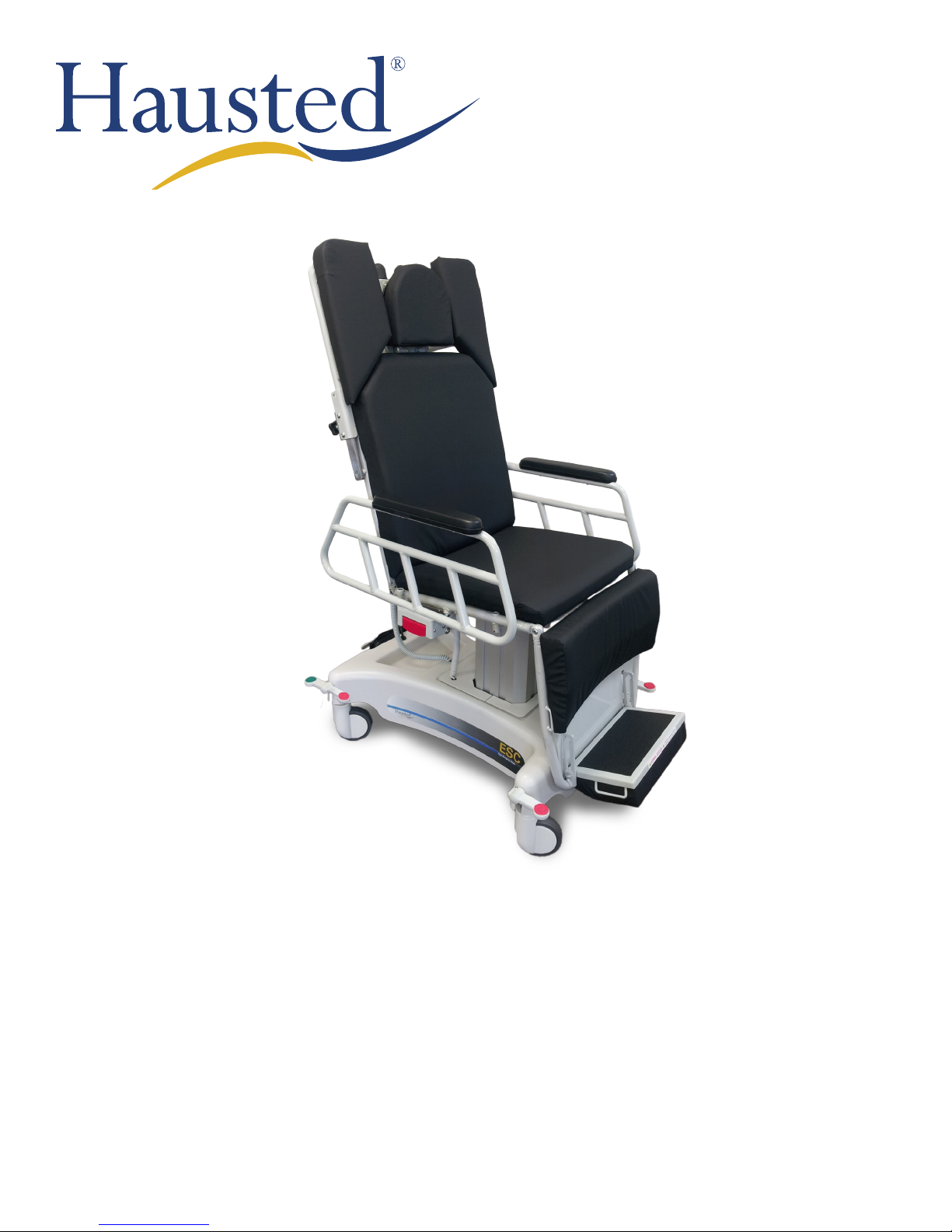
APC SERIES MODELS AND SURGI-CHAIRS —
ELECTRIC POWERED MODELS: EPC, EPD, ESC, & ESD
OPERATING MANUAL
READ THIS MANUAL BEFORE OPERATING YOUR APC / SURGI-CHAIR.
SAVE THIS MANUAL FOR FUTURE USE.
THE MOST CURRENT VERSION OF THIS MANUAL CAN BE FOUND ONLINE AT
WWW.HAUSTED.COM.
APC-IN-INS-LAB-REVA14
Page 2

CONTENTS
INTRODUCTION — A WORD FROM GF HEALTH PRODUCTS, INC. ..................................................................................................... 4
INDICATIONS FOR USE ..................................................................................................................................................................... 4
SERVICE INFORMATION ................................................................................................................................................................... 4
ADVISORY ........................................................................................................................................................................................... 4
1 LIST OF WARNINGS AND CAUTIONS .............................................................................................................................................. 5
SIGNIFICANCE OF SAFETY STATEMENTS ...................................................................................................................................... 5
DANGER / WARNING / CAUTION / NOTICE SUMMARY ........................................................................................................... 5
WARNING: TO REDUCE THE RISK OF BURNS, FIRE, ELECTRIC SHOCK, OR PERSONAL INJURY .................. 5
WARNING — CAUTIONS AND PROPER OPERATION ..................................................................................................................... 6
2 UNCRATING INSTRUCTIONS ............................................................................................................................................................ 8
IMPORTANT — REPORT ANY SHIPPING DAMAGE IMMEDIATELY: .............................................................................................. 8
NOTICE — POSSIBLE EQUIPMENT DAMAGE: ............................................................................................................................... 8
WARNING — PERSONAL INJURY HAZARD: ................................................................................................................................... 8
ENVIRONMENTAL CONDITIONS ...................................................................................................................................................... 8
OPERATING ................................................................................................................................................................................. 8
STORAGE AND TRANSPORT .................................................................................................................................................... 8
UNPACKING INSTRUCTIONS ............................................................................................................................................................ 8
3 OPERATING INSTRUCTIONS ............................................................................................................................................................ 9
3.1 APC / SURGI-CHAIR SPECIFICATIONS ..................................................................................................................................... 9
ELECTRICAL SPECIFICATIONS (APPLIES ONLY TO EPC AND ESC MODELS) ................................................................... 9
ELECTRICAL SPECIFICATIONS (APPLIES ONLY TO EPD AND ESD MODELS) ................................................................... 9
3.2 FEATURES, WARNINGS AND PROPER OPERATION OPERATING INSTRUCTIONS .......................................................... 10
WARNINGS — CAUTIONS AND PROPER OPERATION (SEE DIAGRAM ON FOLLOWING PAGE) .................................... 10
FEATURES (SHOWN IN ILLUSTRATION) .................................................................................................................................11
WARNINGS — CAUTIONS AND PROPER OPERATION (SEE LIST ON PREVIOUS PAGE) ..................................................11
3.3 BRAKING AND STEERING OPERATION ................................................................................................................................. 12
3.3.1 APPLYING THE BRAKES ........................................................................................................................................... 12
3.3.2 RELEASING THE BRAKES ........................................................................................................................................ 12
3.3.3 APPLYING THE STEERING BRAKES ........................................................................................................................ 12
3.3.4 RELEASING THE STEERING BRAKES ..................................................................................................................... 12
3.4 ELECTRIC CONTROL LOCATIONS ......................................................................................................................................... 13
3.4.1 PENDANT CONTROL LOCATION .............................................................................................................................. 13
3.4.2 PLUG LOCATION ........................................................................................................................................................ 13
3.4.3 LOW BATTERY LIGHT (LED) ..................................................................................................................................... 13
3.5 TOP ADJUSTMENTS ................................................................................................................................................................. 14
3.5.1 HEIGHT ADJUSTMENT ............................................................................................................................................... 14
RAISING THE HEIGHT ................................................................................................................................................ 14
LOWERING THE HEIGHT ........................................................................................................................................... 14
3.5.2 FOOT SECTION ADJUSTMENT ................................................................................................................................. 14
RAISING THE FOOT SECTION ................................................................................................................................... 14
LOWERING THE FOOT SECTION .............................................................................................................................. 14
3.5.3 BACK SECTION ADJUSTMENT ................................................................................................................................. 14
RAISING THE BACK SECTION .................................................................................................................................. 14
LOWERING THE BACK SECTION ............................................................................................................................. 14
3.5.4 QUICK DROP ACTIVATION ........................................................................................................................................ 15
3.6 ADJUSTABLE FOOTREST ........................................................................................................................................................ 16
3.6.1 REPOSITIONING THE FOOTREST ............................................................................................................................ 16
3.7 HINGING RAILS ......................................................................................................................................................................... 17
3.7.1 REPOSITIONING THE RAIL ........................................................................................................................................ 17
3.8 ESCEYE / ESDEYE HEADREST ............................................................................................................................................... 18
3.8.1 PRE-OP / POST-OP HEAD EXTENSION .................................................................................................................... 18
3.8.2 ADJUSTING THE HEADREST .................................................................................................................................... 18
3.9 COMMON OPTIONAL ACCESSORIES ..................................................................................................................................... 19
3.9.1 MOUNTING THE WRIST REST ................................................................................................................................... 19
APC-IN-INS-LAB-RevA14 2
Page 3

3.9.2 ADJUSTING THE WRIST REST .................................................................................................................................. 19
3.9.3 INSTALLING #18 IV ROD ............................................................................................................................................ 19
3.9.4 INSTALLING THE SIDE TRAY .................................................................................................................................... 19
3.9.5 USING RESTRAINT STRAPS ..................................................................................................................................... 20
3.9.6 INSTALLING THE PATIENT TRAY .............................................................................................................................. 20
4 TROUBLESHOOTING GUIDE .......................................................................................................................................................... 21
4.1 ELECTRIC POWERED CHAIRS ................................................................................................................................................ 21
4.2 BATTERY REPLACEMENT INSTRUCTIONS ........................................................................................................................... 21
5 PREVENTIVE MAINTENANCE FOR THE USER ............................................................................................................................. 22
6 OPTIONAL ACCESSORIES .............................................................................................................................................................. 23
7 GF HEALTH PRODUCTS, INC. LIMITED WARRANTY FOR HAUSTED BRAND PRODUCT LINE OUTSIDE THE U.S. ............ 24
8 DISPOSAL AND KEY TO SYMBOLS ............................................................................................................................................... 25
DISPOSAL ......................................................................................................................................................................................... 25
KEY TO SYMBOLS ........................................................................................................................................................................... 25
9 APPENDIX ......................................................................................................................................................................................... 26
9.1 GUIDANCE AND MANUFACTURER’S DECLARATION —
ELECTROMAGNETIC EMISSIONS ........................................................................................................................................... 26
9.2 GUIDANCE AND MANUFACTURER’S DECLARATION — ...................................................................................................... 26
9.3 GUIDANCE AND MANUFACTURER’S DECLARATION — ELECTROMAGNETIC IMMUNITY .............................................. 27
9.4 RECOMMENDED SEPARATION DISTANCES BETWEEN PORTABLE AND MOBILE RF COMMUNICATIONS EQUIPMENT
AND HAUSTED APC SERIES MODELS AND SURGI-CHAIRS ............................................................................................... 28
10 INDEX ................................................................................................................................................................................................ 29
GF Health Products, Inc. is not responsible for typographical errors. All illustrations,
specications, packaging and warranties contained in this document are based on the latest
product information available at the time of printing. The most current product information,
including the most current revision of this manual, can be found online at www.grahamfield.com.
Graham-Field and Hausted are registered trademarks of GF Health Products, Inc.
COPYING PROHIBITED
This manual is protected by Federal Copyright Law, which provides for damages of up to USD
$20000, as well as criminal nes and imprisonment, for unauthorized copying.
© 2014 GF Health Products, Inc. All Rights Reserved Printed in U.S.A.
APC-IN-INS-LAB-RevA14 3
Page 4
INTRODUCTION — A WORD FROM GF HEALTH PRODUCTS, INC.
This manual contains important information on proper use and maintenance of the Hausted
APC Series models and Surgi-Chairs. All personnel involved in the use and maintenance of this
equipment must carefully review and comply with the warnings, cautions and instructions
contained in this manual. These instructions are important to protect the health and safety of
personnel operating models EPC, EPD, ESC, and ESC and should be retained in a conveniently
accessible area for quick reference.
Complete instructions for uncrating and putting your new equipment in service, as well as
equipment drawings, have been furnished. If missing, contact GF Health Products, Inc. for
replacement copies, giving the serial number and model number of the unit.
GF Health Products, Inc. carries a complete line of accessories for use with these chairs; your
representative will gladly review these with you.
INDICATIONS FOR USE
The Hausted APC Series models and Surgi-Chairs are intended for use in patient treatment,
transport or recovery.
The chair’s backrest can be positioned from sitting to supine. Height positioning, as well as
backrest and leg section adjustment, is electric/battery powered and is activated with a handheld
control. Four easy-rolling, steerable casters allow maximum mobility and maneuverability.
SERVICE INFORMATION
A thorough preventive maintenance program is essential to safe and proper unit operation. This
manual contains maintenance schedules and procedures which should be followed for satisfactory
equipment performance.
We encourage you to contact GF Health Products, Inc. with maintenance concerns.
ADVISORY
A listing of the safety precautions to be observed when operating and servicing this equipment
can be found in Section 1 of this manual. Do not operate or service the equipment until you
have become familiar with this information. Any alteration of this equipment not authorized or
performed by GF Health Products, Inc., could affect its operation, will void the warranty, could
violate national, state, and local regulations, and could jeopardize your insurance coverage.
EC REP
EC Authorized
Representative:
CEpartner4U BV
ESDOORNLAAN 13
3951DB MAARN
The Netherlands
+31(0)6 516 536 26
Manufactured by:
GF Health Products, Inc.
336 Trowbridge Drive
Fond du Lac, WI 54937
678-291-3207 Main
770-368-2386 Fax
www.grahameld.com
www.Hausted.com
Class 1 Equipment
Type B Equipment
Equipment not suitable
for use in the presence
of ammable anesthetic
mixture with air or oxygen
or nitrous oxide.
IPX4 (Splash-proof
equipment)
Not suitable for continuous
operation (Duty Cycle:
5% 1 Min in 19 Min)
Info: The base language of this document is ENGLISH. Any translations must be made from the
base language document.
APC-IN-INS-LAB-RevA14 4
Page 5

1 LIST OF WARNINGS AND CAUTIONS
IMPORTANT: Before using the Hausted APC / Surgi-Chair, please read and adhere to the
following safety precautions and warnings. Failure to do so could result in serious personal
injury or damage to the APC / Surgi-Chair.
Always consult your healthcare professional to determine safe methods most suitable for your
individual abilities. Protect yourself, your attendant, and the Hausted APC / Surgi-Chair by having
it serviced regularly. If you experience any malfunction, contact your Graham-Field authorized
distributor immediately, as a hazardous condition could result, causing personal injury or damage
to the Hausted APC / Surgi-Chair.
Periodic inspection, adjustment and replacement of worn parts are necessary to provide years of
excellent service. Maintenance MUST be performed by qualied personnel ONLY.
SAVE THESE INSTRUCTIONS.
SIGNIFICANCE OF SAFETY STATEMENTS
Please note the following special statements, used throughout this manual, and their signicance:
DANGER: Indicates a potential hazard situation or unsafe practice that, if not avoided, will
result in death or serious personal injury.
WARNING: Indicates a potential hazard situation or unsafe practice that, if not avoided,
could result in death or serious personal injury.
CAUTION: Indicates a potential hazard situation or unsafe practice that, if not avoided,
could result in minor or moderate personal injury.
s NOTICE: Indicates a potential hazard situation or unsafe practice that, if not avoided, could
result in product or property damage.
Info: Provides application recommendations or other useful information to ensure that you get
the most from your product.
DANGER / WARNING / CAUTION / NOTICE Summary
The following is a listing of the safety precautions which must be observed when operating and
servicing this equipment. These precautions are repeated (in whole or in part), where applicable,
throughout the manual.
WARNING: To Reduce the Risk of Burns, Fire, Electric Shock, or Personal Injury
DANGER: SHOCK HAZARD — To reduce the risk of electric shock, do not remove the
cover. Unit is to be serviced by qualied personnel only.
DANGER: SHOCK HAZARD — To avoid risk of electric shock, this equipment must only be
connected to a supply mains with protective earth.
WARNING: LACERATION HAZARD — When cutting bands always us a tool specically
designed for that purpose. This will help to avoid personal injuries frequently incurred
when bands are cut and tension released.
WARNING: PERSONAL INJURY HAZARD — The batteries are wired in series; failure to
connect the same way can cause batteries to explode.
APC-IN-INS-LAB-RevA14 5
Page 6

WARNING — CAUTIONS AND PROPER OPERATION
WARNING: This product has a maximum weight capacity of 227 kilograms (500 lb),
EVENLY DISTRIBUTED.
WARNING: The chair is not intended to replace a stretcher or gurney.
WARNING: Do not sit on end of chair — tipping may occur.
WARNING: Do not stand on footrest — tipping may occur.
WARNING: When not in use, do not leave the chair in a recline position.
WARNING: When patient is seated in the chair, ensure the side rails are up and the patient
is secured with patient restraint straps.
WARNING: Patient entry, egress and transfer from the chair should always be from the
center side rail location with the side rail in the down position and the brakes locked.
WARNING: At no time should the patient be permitted to enter or exit from the ends of the
chair when in partial or total recline position.
WARNING: Ensure the brakes are locked when the patient is not being transported.
WARNING: Place pendant in holder when not in use, and keep cord clear of moving parts.
WARNING: All electric powered chairs are equipped with a built in battery back-up
system: nevertheless, the unit should remain plugged into wall receptacle during normal
use. The battery back-up is recommended for transport and emergency only.
WARNING: The backrest quick drop handle is intended to be used during emergency
situations only
WARNING: To turn electric controls on, plug into wall receptacle. To turn off, remove plug
from wall receptacle. The electric powered chairs do not have a separate on/off switch.
WARNING: To reduce the risk of electrical shock do not remove the control box cover.
Service by qualied personnel only.
WARNING: Always disconnect the power source whenever troubleshooting or servicing
any electric powered chair.
WARNING: Do not use a sharp instrument to remove fuse, as it may scratch the circuit
board.
WARNING: The batteries are wired in series; failure to install or rewire the same way may
cause the batteries to explode.
WARNING: Medical Electrical Equipment needs special precautions regarding EMC and
needs to be installed and put into service according to the EMC information provided in this
manual.
WARNING: Portable and mobile RF communications equipment can affect Medical
Electrical Equipment.
WARNING: The use of accessories, transducers, and cables other than those specied by
the manufacturer may result in increased Emissions or decreased Immunity of the Hausted
Equipment.
WARNING: The Hausted Equipment should not be used adjacent to or stacked with other
equipment; if adjacent or stacked use is necessary, the Hausted equipment should be
observed to verify normal operation in the conguration in which it will be used.
APC-IN-INS-LAB-RevA14 6
Page 7

WARNING: Steam cleaning and pressure washing of chair is not recommended and can
void warranty.
WARNING: Rail release handle will not release unless force is applied laterally to outside
top of rail.
WARNING: Possible pinch point — do not place hands between seat section and side rail.
WARNING: NOTICE FOR CALIFORNIA CUSTOMERS- California Proposition 65 Warning:
This product contains a chemical known to the State of California to cause cancer and
reproductive or developmental harm.
APC-IN-INS-LAB-RevA14 7
Page 8
2 UNCRATING INSTRUCTIONS
IMPORTANT — REPORT ANY SHIPPING DAMAGE IMMEDIATELY:
WARNING: Inform shipper of any damages — leave carton intact. Leave equipment in the
receiving area until inspection is complete.
NOTICE — POSSIBLE EQUIPMENT DAMAGE:
s NOTICE: The crate contains fragile, expensive medical equipment. Uncrate and handle
carefully. If after uncrating the equipment you nd any damage (no matter how slight),
report the damage to GF Health Products, Inc.
WARNING — PERSONAL INJURY HAZARD:
WARNING: When cutting bands, always use tool specically designed for that purpose.
This will help avoid personal injuries possibly incurred when bands are cut and tension is
released.
ENVIRONMENTAL CONDITIONS
Operating
Temperature 5°C to +40°C
Relative Humidity 20% to 90% @ 30°C
Atmospheric Pressure 700 to 1060 hPa
Storage and Transport
Temperature -10°C to +50°C
Relative Humidity 20% to 90% @ 30°C
Atmospheric Pressure 700 to 1060 hPa
IMPORTANT: Follow each step in the order shown in these instructions.
UNPACKING INSTRUCTIONS
Your Hausted equipment has been carefully packed at our manufacturing plant to ensure safe
shipment to your medical facility. There are several procedures you must follow to put your new
equipment in service. These procedures only take a few minutes to complete and all are required
to ensure proper operation of the equipment.
1. Cut the two bands around the shipping carton.
2. Remove the top half of the carton and cut one side of the bottom half.
3. Remove the equipment from the carton.
4. Check to see if all features of the equipment work properly. If all the features work, advance to
step 5. If any of the features do not work properly, call GF Health Products, Inc. at 678-291-3165.
Info: Although the equipment has been fully charged prior to shipment, plug the unit into a wall
socket prior to checking any electric features.
5. Clean the equipment using mild detergent to remove any dirt accumulated during shipment,
and place the equipment into service.
APC-IN-INS-LAB-RevA14 8
Page 9
3 OPERATING INSTRUCTIONS
3.1 APC / SURGI-CHAIR SPECIFICATIONS
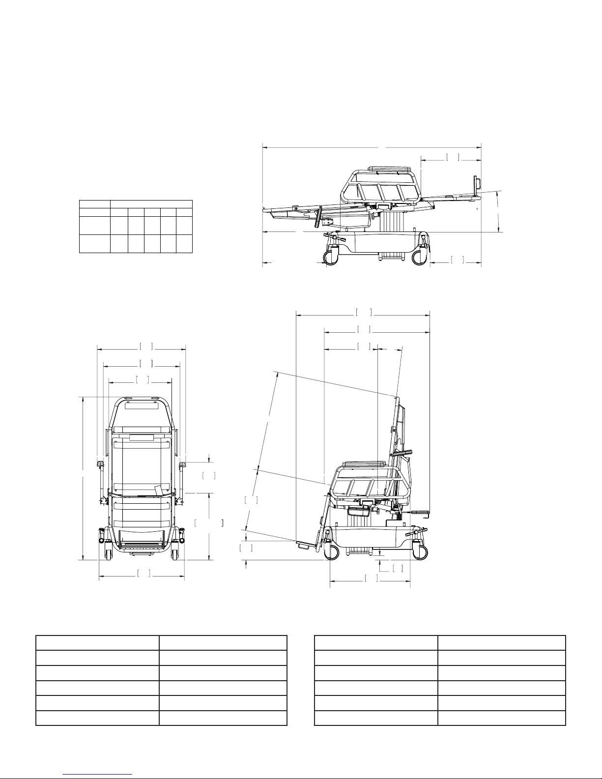
Info: All dimensions are specified in inches. All dimensions are ±.375. Stacked dimensions are
minimum (top) and maximum (bottom). GF Health Products, Inc. reserves the right to change
specifications without notice.
MODEL
EPC250/
EPD250
ESC250/
ESD250
DIMENSION
A B
54.2/
72.7 25.9 21.3 33.2
62.45
56.7/
75.0 28.2 23.6 35.0
64.95
748
29.4
648
25.5
533
21.0
C D
B
E
C
D
(TO BASE COVER)
1129
44.5
891
35.1
450
17.7
7°
E
509
20.0
17.0
431
TRENDELENBERG
6
A
722
28.4
Electrical Specications (Applies only
to EPC and ESC Models)
Product Classication: 1
Input Voltage: 120V~, ±5%, 60Hz
Amperage: Max. 3.5A
Duty Cycle: 5% 1 Min in 19 Min
IP Rating: IPX 4
Grounding Protection: Type B
565
22.3
260
10.2
/
768/
30.3
160
6.3
521
20.5
38
1.5
679
26.7
Electrical Specications (Applies only
to EPD and ESD Models)
Product Classication: 1
Input Voltage: 230V~, ±10%, 50Hz
Amperage: Max. 1.9A
Duty Cycle: 5% 1 Min in 19 Min
IP Rating: IPX 4
Grounding Protection: Type B
APC-IN-INS-LAB-RevA14 9
Page 10

3.2 FEATURES, WARNINGS AND PROPER OPERATION OPERATING
INSTRUCTIONS
WARNINGS — CAUTIONS AND PROPER OPERATION (See Diagram on following
page)
A. WARNING: The chair has a warning label located on the back section stating:
Maximum patient weight 227 kilograms (500 lbs.)
B. WARNING: The chair is not intended to replace a stretcher or gurney.
C. WARNING: The chair has warning labels on both the head and foot end stating: Do not
sit on end - as tipping may occur.
D. WARNING: Do not stand on footrest — tipping may occur.
E. WARNING: When not in use, do not leave the chair in a recline position.
F. WARNING: When patient is seated in the chair, ensure the side rails are up and the
patient is secured with patient restraint straps.
G. WARNING: Patient entry, egress and transfer from the chair should always be from the
center side rail location with the side rail in the down position and the brakes locked.
H. WARNING: At no time should the patient be permitted to enter or exit from the ends of
the chair when in partial or total recline position.
I. WARNING: Ensure the brakes are locked when the patient is not being transported.
J. WARNING: The patient pendant has a warning label on it stating: Place pendant in
holder when not in use — keep cord clear of moving parts.
K. WARNING: All electric-powered chairs are equipped with a built in battery back-up
system, but it is recommended that the unit remain plugged in wall receptacle during
normal use. The battery back-up is recommended for transport and emergency only.
L. WARNING: The backrest quick drop handle is intended to be used during emergency
situations only.
M. WARNING: To turn electric controls on, plug into wall receptacle. To turn off, remove
plug from wall receptacle. The electric powered chairs do not have a separate on/off switch.
N. WARNING: The chair has a warning label located on the control box cover stating: To
reduce the risk of electrical shock do not remove the cover. Service by qualied personnel
only.
O. WARNING: Always disconnect the power source whenever servicing any electric
powered chair.
P. WARNING: Do not use a sharp instrument to remove fuse, as it may scratch the circuit
board.
Q. WARNING: The batteries are wired in series; failure to install or rewire the same way
may cause the batteries to explode.
R. WARNING: Rail release handle will not release unless force is applied laterally to
outside top of rail.
S. WARNING: The chair has a warning label located on both side rails indicating a pinch
point between seat section and side rail.
APC-IN-INS-LAB-RevA14 10
Page 11
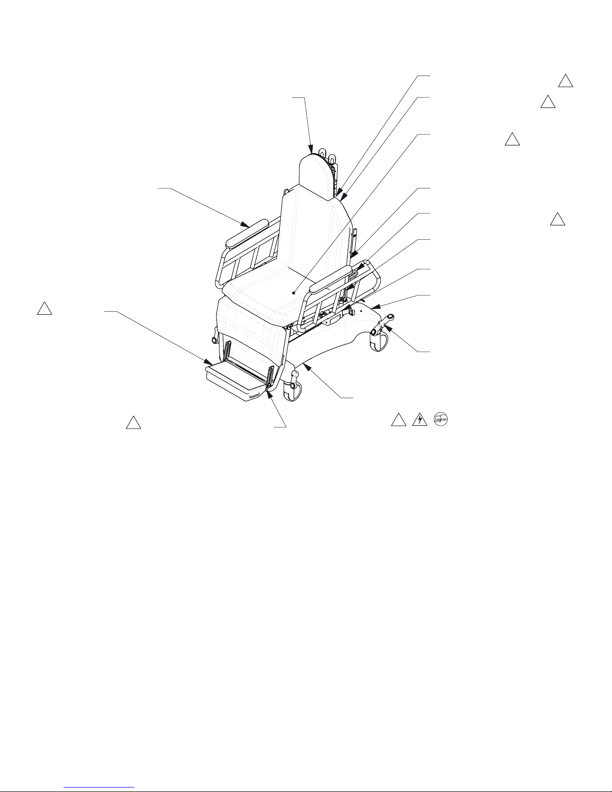
Features (Shown in Illustration)
HINGING RAIL
See Warning F
ADJUSTABLE FOOT REST WARNING LABEL
!
See Warning D
PATIENT COMFORT CUSHIONS
HEAD SECTION TUBE WARNING LABEL
See Warnings C & H
BACK OF CHAIR WARNING LABEL
See Warning A
PATIENT ENTRY
See Warnings G & H
EMERGENCY QUICK DROP HANDLE
See Warning L
PATIENT PENDANT WARNING LABEL
See Warning K
RESTRAINT ROD
See Warning F
RAIL LATCH
See Warnings F, R, & S
POWER CORD
See Warning F
BRAKE PEDAL
See Warnings G thru I
!
!
!
!
ELECTRIC CONTROL BOX & CIRCUITRY
See Warnings M thru Q
FOOT SECTION TUBE WARNING LABEL
!
See Warnings C & H
!
WARNINGS — CAUTIONS AND PROPER OPERATION (See List on Previous Page)
APC-IN-INS-LAB-RevA14 11
Page 12
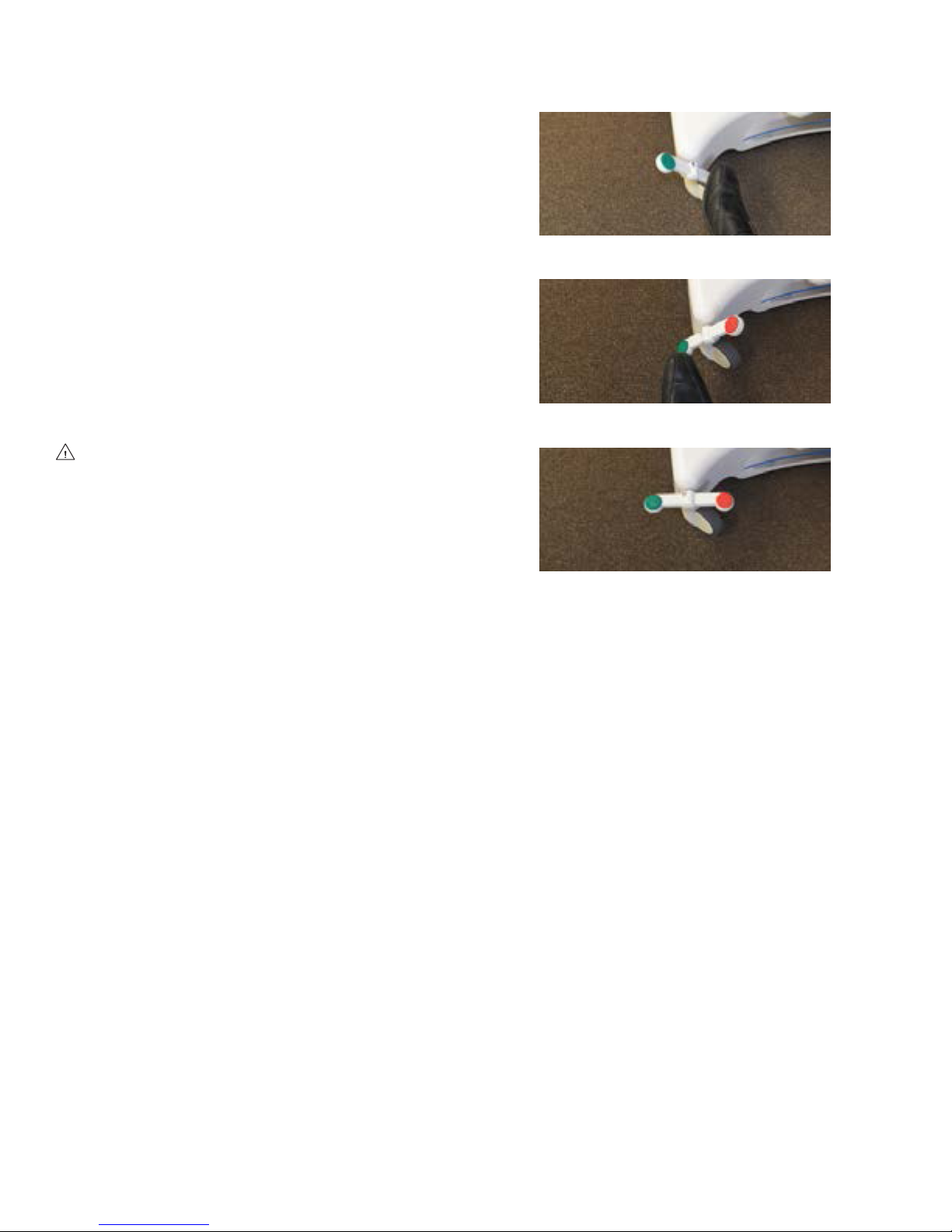
3.3 BRAKING AND STEERING OPERATION
3.3.1 Applying the Brakes
Activate the four wheel central braking system
by depressing the red pedal at any of the four
corners of the unit (Figure 3-1).
Engage the brakes fully by depressing the pedal
to approximately 45°. All four caster wheels
should then be locked from swiveling and
rotating.
3.3.2 Releasing the Brakes
Release the brakes by depressing either green
pedal at the head end of the unit until the pedal
is in a horizontal position (Figure 3-2). All four
wheels should then rotate and swivel freely.
WARNING: Ensure the brakes are locked
when the patient is not being transported.
FIGURE 3-1
FIGURE 3-2
3.3.3 Applying the Steering Brakes
From the head end of the chair, depress the
green pedal downward into locked position
(Figure 3-3). Push the chair forward. Both casters
at the foot end will lock into nonswivel mode;
the steering lock will then guide the chair along a
straight path with minimal steering effort by the
attendant.
3.3.4 Releasing the Steering Brakes
Release the steering brakes by depressing either
red pedal at the head end of the unit until the
pedal is in a horizontal position (Figure 3-2). All
four casters should then rotate and swivel freely.
FIGURE 3-3
APC-IN-INS-LAB-RevA14 12
Page 13
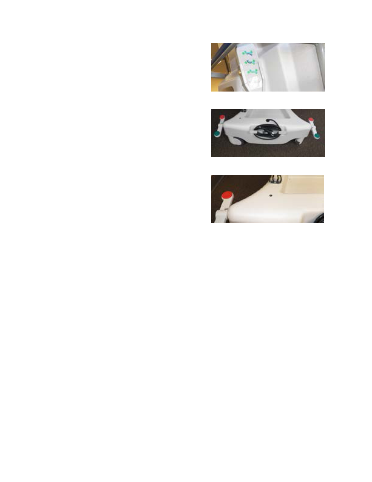
3.4 ELECTRIC CONTROL LOCATIONS
3.4.1 Pendant Control Location
The pendant is located in the pendant holder on
the back of the chair (Figure 3-4).
This chair is equipped with a battery back up for
transport but the unit should be plugged into a
wall receptacle when not in transport. The plug
is located on the back of the base cover (Figure
3-5). Do not position the unit so that it is difcult
to disconnect the plug.
s NOTICE: Place pendant in holder when not
in use. Keep cord clear of moving parts.
3.4.2 Plug Location
This chair is equipped with a battery back up for
transport but the unit should be plugged into a
wall receptacle when not in transport. The plug
is located on back of the base cover (Figure 3-5).
Do not position the unit so that it is difcult to
disconnect the plug.
FIGURE 3-4
FIGURE 3-5
Important: It is recommended that unit remain
plugged in wall receptacle during normal use.
Battery back-up is recommended for transport
and emergency only.
3.4.3 Low Battery Light (LED)
This chair is equipped with a low battery
indicator light, located on top of the base cover
of the patient’s left (Figure 3-6). When a button
on the pendant is pressed, and the LED light
illuminates, it indicates that the backup batteries
require charging; plug the unit into the wall
receptacle.
FIGURE 3-6
APC-IN-INS-LAB-RevA14 13
Page 14
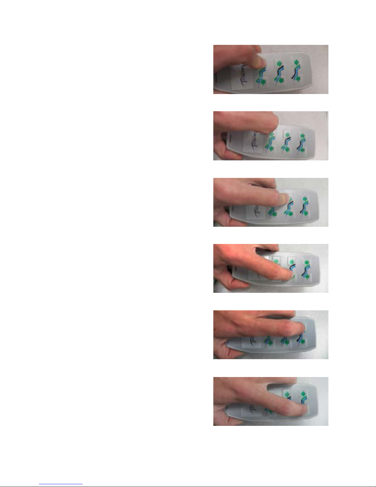
3.5 TOP ADJUSTMENTS
3.5.1 Height Adjustment
Remove the pendant from pendant holder, (see
Section 3.4.1, Pendant Control ).
Raising the Height
Press the rst button on the third row of buttons
on the pendant (Figure 3-7); hold until the
desired height is achieved.
Lowering the Height
Press the second button on the third row of
buttons on the pendant (Figure 3-8); hold until
the desired height is achieved.
FIGURE 3-7
s NOTICE: Place pendant in holder when not
in use. Keep cord clear of moving parts.
3.5.2 Foot Section Adjustment
Raising the Foot Section
Press the rst button on the second row of
buttons on the pendant (Figure 3-9); hold until
the desired angle is achieved.
Lowering the Foot Section
Press the second button on the second row of
buttons on the pendant (Figure 3-10); hold until
the desired angle is achieved.
3.5.3 Back Section Adjustment
Raising the Back Section
Press the rst button on the rst row of buttons
on the pendant (Figure 3-11); hold until the
desired incline is achieved.
FIGURE 3-8
FIGURE 3-9
FIGURE 3-10
Lowering the Back Section
Press the second button on the rst row of
buttons on the pendant (Figure 3-12); hold until
the desired recline is achieved.
APC-IN-INS-LAB-RevA14 14
FIGURE 3-11
FIGURE 3-12
Page 15

3.5.4 Quick Drop Activation
This chair is equipped with a manual override
function for the back section of the chair. This
option should only be used in an emergency
situation. To activate the quick drop, support
the back section and pull upward on the red
activating handle located on the back of the
chair (Figure 3-13).
FIGURE 3-13
APC-IN-INS-LAB-RevA14 15
Page 16
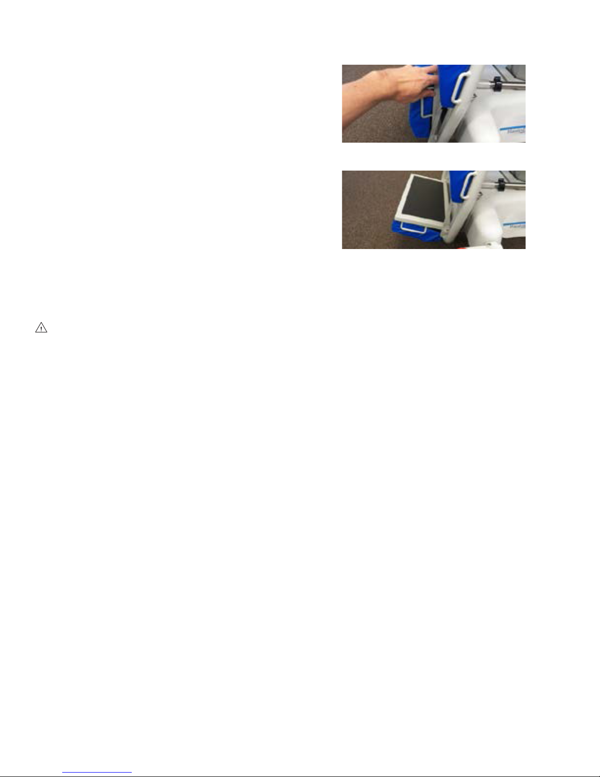
3.6 ADJUSTABLE FOOTREST
FIGURE 3-13
3.6.1 Repositioning the Footrest
The footrest has three positions: retracted,
lower, and upper. With the pan in the retracted
position, pull out on the handles on either side of
pan (Figure 3-14). The footrest will drop into the
lower position.
To place the footrest into the upper position,
grasp the handles on both sides of the pan. Tilt
the pan up while lifting (Figure 3-14). Once the
pan is in the fully up position, tilt the pan out
until it locks into the upper position (Figure
3-15).
FIGURE 3-14
To return the footrest to the retracted position,
tilt the pan up while letting it slide down (Figure
3-14) into the lower standard position. Continue
tilting the footrest until it is in the retracted
position.
WARNING: TIPPING HAZARD — Do not
stand on footrest — tipping may occur.
FIGURE 3-15
APC-IN-INS-LAB-RevA14 16
Page 17
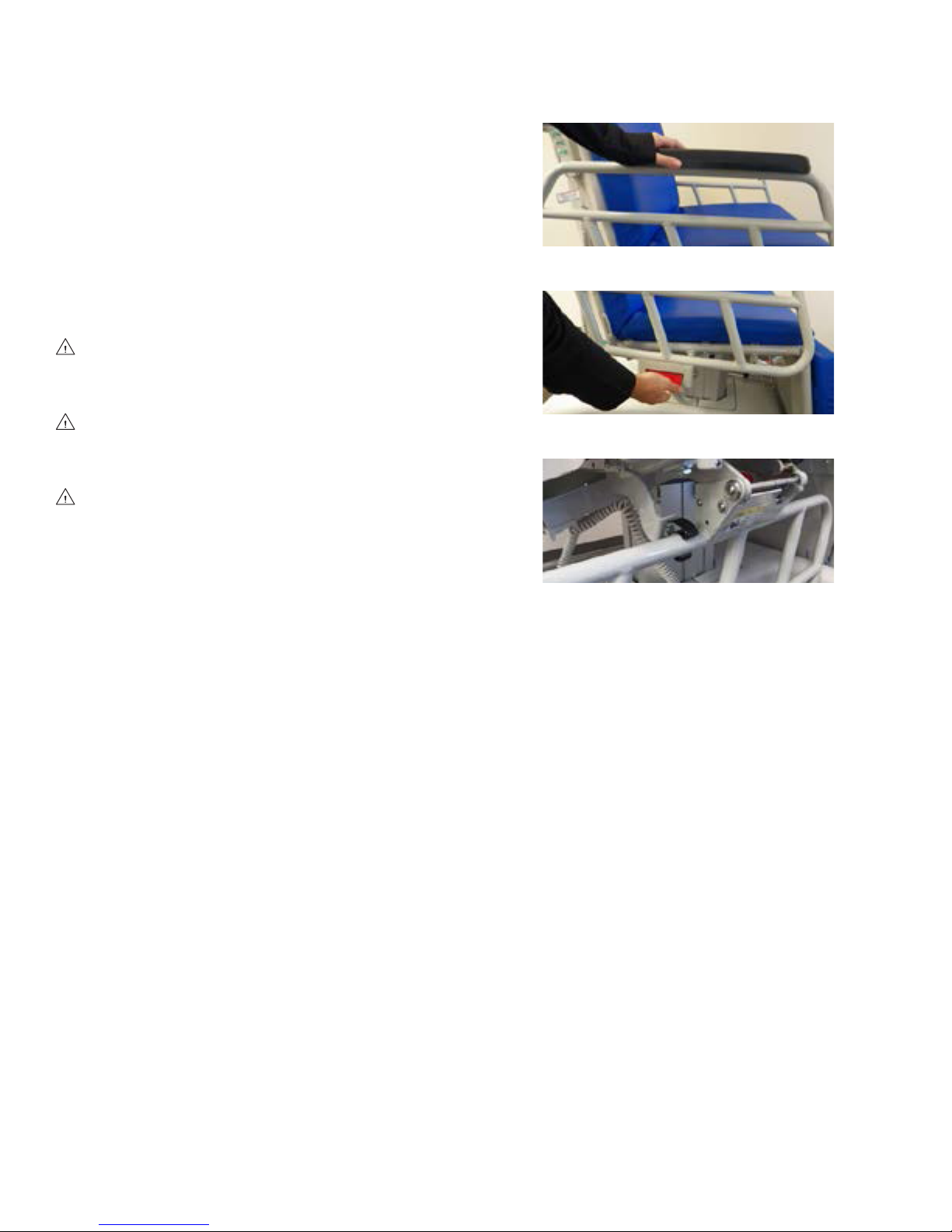
3.7 HINGING RAILS
3.7.1 Repositioning the Rail
The chair rail has two positions, up and down.
Both positions lock the rail into place. To lower
the rail, apply a lateral force to the top of the
rail (Figure 3-16) and pull on the red rail handle
(Figure 3-17). Allow the rail to hinge all the way
down until it locks into place in the rail catch
(Figure 3-18). To raise the rail, take hold of the
rail and lift it until the latching mechanism locks
into place. (Figure 3-16).
WARNING: When patient is seated in the
chair, ensure the side rails are up and the
patient is secured with restraint straps.
FIGURE 3-16
WARNING: Rail release handle will not
release unless force is applied laterally to
outside top of rail.
WARNING: The chair has a warning label
located on both side rails indicating a pinch
point between seat section and side rail.
FIGURE 3-17
FIGURE 3-18
APC-IN-INS-LAB-RevA14 17
Page 18
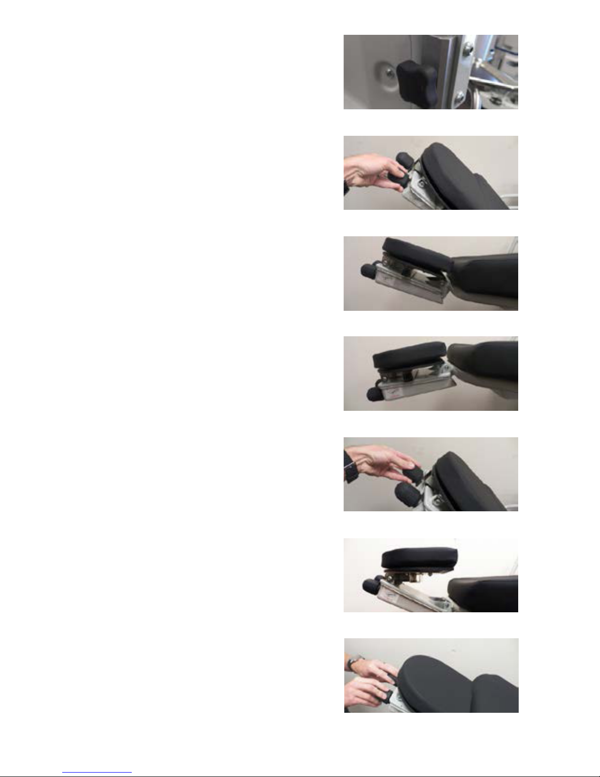
3.8 ESCEYE / ESDEYE HEADREST
3.8.1 Pre-op / Post-op Head Extension
To remove the head extension, rotate the
knobs on the two ends of the extension
counterclockwise (Figure 3-19). With knobs
loose, pull out on the extension. To install the
extension, slide the extension over the surgical
mounting bars using the guides on the extension.
Slide the extension fully down the surgical side
bars, then tighten the knobs on the end of the
extension.
FIGURE 3-19
s NOTICE: Ensure the head extension is
secure before applying any pressure.
3.8.2 Adjusting the Headrest
Remove head extension (see Pre-op / Post-op
Head extension, Section 3.8.1). Grasp the right
ball style knob (Figure 3-20), and rotate the knob
counterclockwise to articulate the head section
upward (Figure 3-21). Rotate the knob clockwise
to articulate the head section downward (Figure
3-22). Once the upward articulation has been set,
grasp the left ball style knob (Figure 3-23), and
rotate the knob counterclockwise to adjust the
height of the headrest (Figure 3-24).
Info: After understanding which knob creates
which action, quick and smooth adjustment
can be achieved by rotating the knobs
simultaneously (Figure 3-25).
FIGURE 3-20
FIGURE 3-21
FIGURE 3-22
APC-IN-INS-LAB-RevA14 18
FIGURE 3-23
FIGURE 3-24
FIGURE 3-25
Page 19
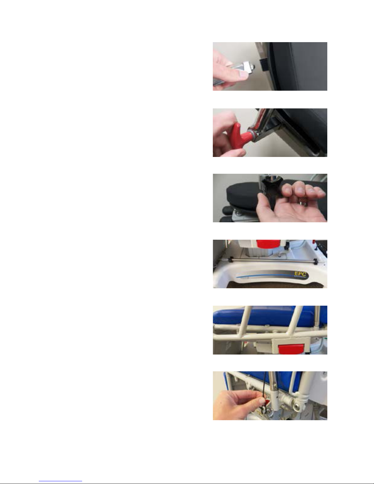
3.9 COMMON OPTIONAL ACCESSORIES
FIGURE 3-25
3.9.1 Mounting the Wrist Rest
Place the wrist rest into one of the three square
sockets under the headrest (Figure 3-26). Rotate
the T-knob on the back of the wrist rest (Figure
3-27) clockwise.
s NOTICE: Ensure the wrist rest is secure
before applying any pressure.
3.9.2 Adjusting the Wrist Rest
Properly install the wrist rest (see the eye
headrest instructions). Support the wrist rest
and loosen the black star knob on the side of the
support post (Figure 3-28).
Position the wrist rest to desired height and
rotation. Tighten the star knob located on the
side of the support post (Figure 3-28).
s NOTICE: Ensure the wrist rest is secure
before applying any pressure.
3.9.3 Installing #18 IV Rod
Remove the IV Rod from the clips located on the
base (Figure 3-29). Insert IV Rod into preferred
socket (Figure 3-30). Place IV Rod back into
storage clips when not in use (Figure 3-29).
FIGURE 3-26
FIGURE 3-27
FIGURE 3-28
3.9.4 Installing the Side Tray
Insert pin end of Side Tray assembly into
preferred socket on the seat section. Align hole
in pin with hole in seat section socket and insert
locking pin to prevent movement of tray (Figure
3-31).
FIGURE 3-29
FIGURE 3-30
FIGURE 3-31
APC-IN-INS-LAB-RevA14 19
Page 20
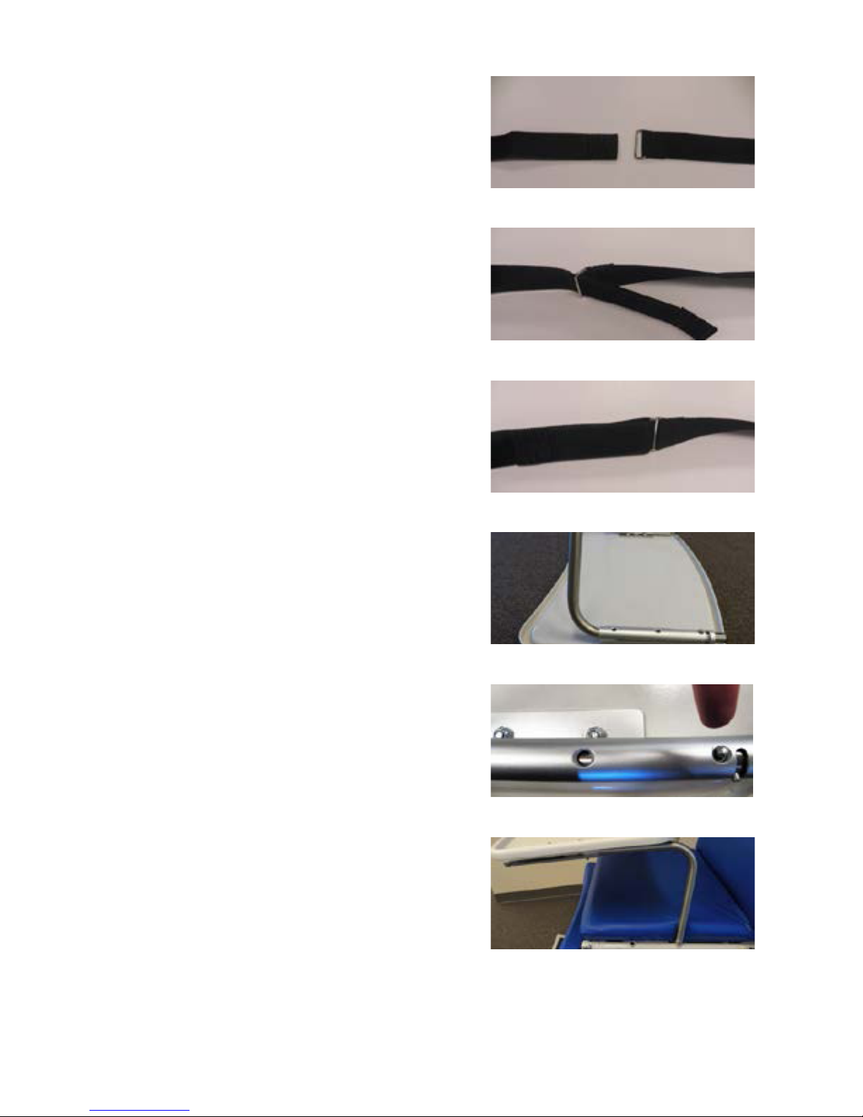
3.9.5 Using Restraint Straps
Locate both ends of the restraint strap, on either
side of the chair. One will have a square loop on
the end, and the other will have hook and loop
fasteners (Figure 3-32). Slide the end of the strap
with the hook and loop fasteners through the
loop on the other strap (Figure 3-33). Pull out
on the strap until the patient is secure. Fold the
hook and loop fastener end of the strap back
until it makes contact with the mating hook and
loop fastener on the strap (Figure 3-34).
3.9.6 Installing the Patient Tray
Using the push buttons underneath the tray, lock
the legs 90° to the tray prior to installing (Figure
3-35). Check to make sure that the legs are
located in the same hole (Figure 3-36). Insert the
rst leg into preferred socket on one side of the
patient, and insert second leg into corresponding
socket on other side (Figure 3-47). Adjust as
necessary to best t patient.
FIGURE 3-32
FIGURE 3-33
FIGURE 3-34
FIGURE 3-35
FIGURE 3-36
APC-IN-INS-LAB-RevA14 20
FIGURE 3-37
Page 21
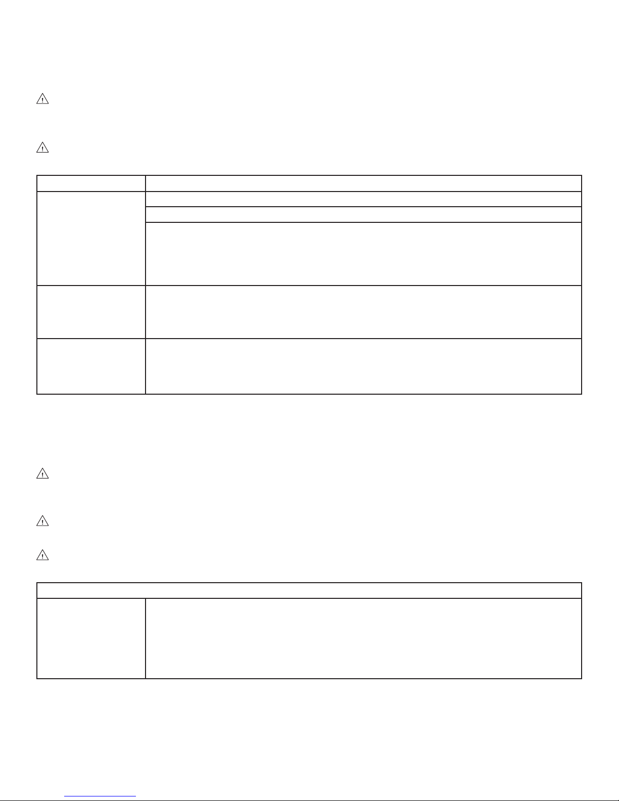
4 TROUBLESHOOTING GUIDE
4.1 ELECTRIC POWERED CHAIRS
DANGER: SHOCK HAZARD — To reduce the risk of electric shock, do not remove the
cover. Unit is to be serviced by qualied service personnel (minimum 1 year medical
equipment service and repair experience) only.
DANGER: SHOCK HAZARD — Always disconnect the power source whenever
troubleshooting or servicing any electric powered chair.
If Then
One motor or one
column does not
move, but all others
are operating
correctly.
Nothing moves. Step 1: Plug unit into a mains supply wall receptacle, then observe the pilot light on the
The unit runs when
plugged into wall
receptacle, but does
not run on battery
backup.
Step 1: Check all motor and column plug connections at the controller box.
Step 2: If a column does not move, check the connection at the column.
Step 3: Plug a connector from the faulty component into a different socket:
If the component does not run: Replace that component.
If the component does run: Test pendant by plugging a functioning component into the
non-functioning socket on the controller. If this component does not run, replace the
pendant. If replacing the pendant does not x the problem, then replace the controller.
controller:
If the pilot light is off: Replace the controller.
If the pilot light is on: Check the pendant control plug connection at the controller.
Step 1: Plug unit into a wall receptacle overnight.
If the batteries do not hold a charge, replace the batteries (section 4.2).
GF Health Products, Inc. may be contacted at 678-291-3165 for additional information required to
service or repair the equipment.
4.2 BATTERY REPLACEMENT INSTRUCTIONS
DANGER: SHOCK HAZARD — To reduce the risk of electric shock, do not remove the
cover. Unit is to be serviced by qualied service personnel (minimum 1 year medical
equipment service and repair experience) only.
DANGER: SHOCK HAZARD — Always disconnect the power source whenever
troubleshooting or servicing any electric powered chair.
WARNING: PERSONAL INJURY HAZARD — The batteries are wired in series; failure to
connect the same way can cause batteries to explode.
The batteries are the only eld serviceable components — do not attempt to repair the circuit boards.
Battery replacement Step 1: Remove the controller.
Step 2: Remove the 4 screws from the right half, located on top of controller.
Step 3: (After 4/11/00) replace (2) batteries with ‘YUSHA’ #NP 1.2-12, 12 volt, 1.2 Ah
batteries (Hausted P/N 075759 – 2 required, for CB-12 controllers).
Step 4: Ensure battery connector is in place on left side of batteries.
Step 5: Replace cover.
APC-IN-INS-LAB-RevA14 21
Page 22
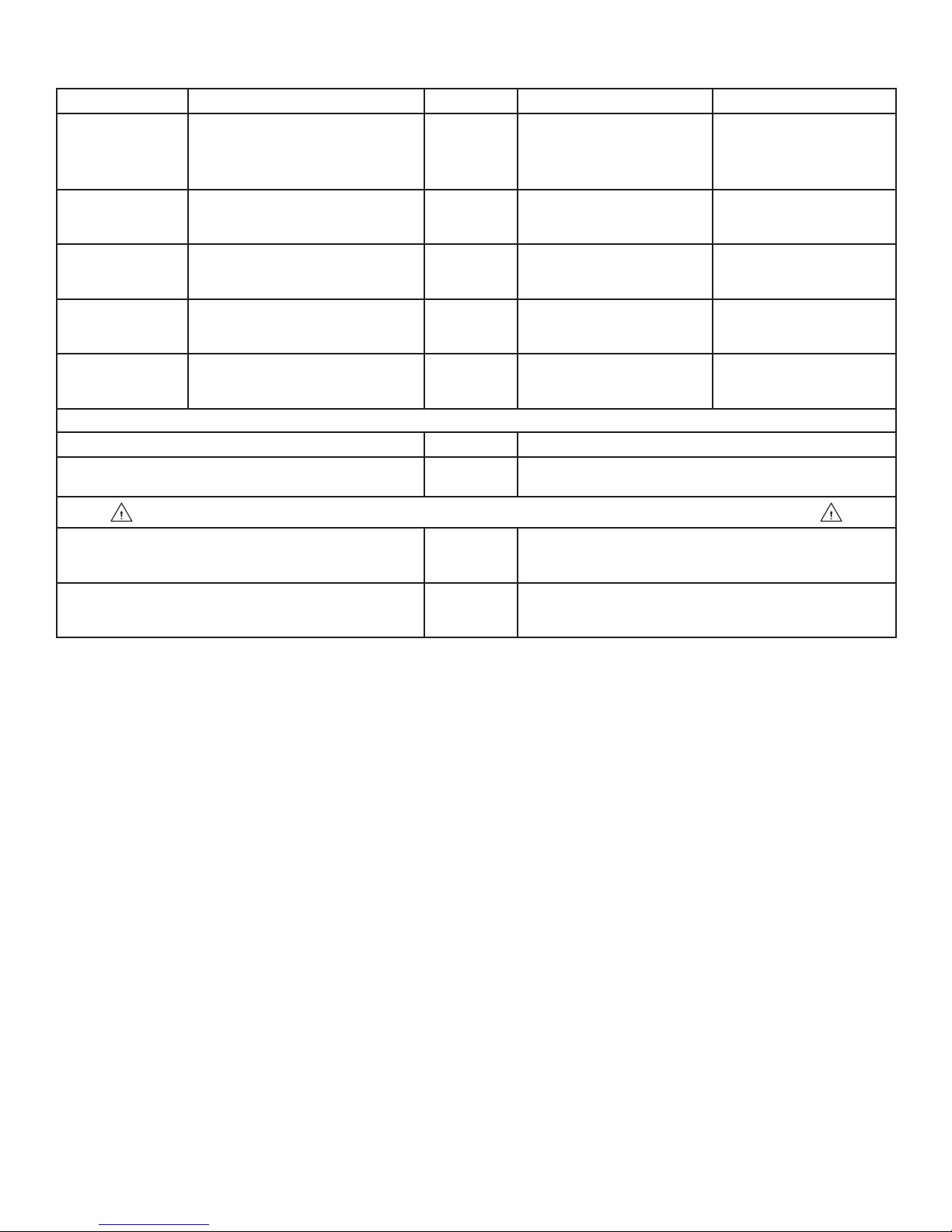
5 PREVENTIVE MAINTENANCE FOR THE USER
Component Cleaning Procedure Schedule Cleaning Agent * Special Notes
Pads/
Mattresses
Chair Wipe with damp cloth to
Electrical
components
Mechanical
chair
components
Mechanical
accessories
Wipe with damp cloth to
remove any foreign material
remove any foreign material
Wipe external surfaces ONLY
with damp cloth to remove
any foreign material
Wipe with damp cloth to
remove any foreign material
Wipe with damp cloth to
remove any foreign material
After each
use
After each
use
After each
use
After each
use
After each
use
Routine hospital grade
disinfectants, soap and
water
Routine hospital grade
disinfectants, soap and
water
Routine hospital grade
disinfectants, soap and
water
Routine hospital grade
disinfectants, soap and
water
Routine hospital grade
disinfectants, soap and
water
Use only medium
strength cleaners
Do not steam clean or
pressure wash
Lubricate pivot points
after cleaning
Use only medium
strength cleaners
Lubricate pivot points
after cleaning
Lubricate pivot points
after cleaning
Procedure Schedule Material
Lubricate all moving and sliding parts and
hinge points
Every 3
months
Lubricating oil, light-duty grease, wax stick
lubricant or Never-Seez lubricant
N EVE R LU BRI CATE GAS SPR ING, MOTO R OR M ECH-LOCK SH AFT S
Inspect all fasteners to ensure proper t,
position and tightness (including nuts, bolts,
etc.)
Inspect all surfaces and remove any sharp
or burred areas; apply touch-up paint where
required
Every 3
months
Every 3
months
Proper size wrench and screwdriver
Metal le, proper color paint (specify color when
ordering)
Disinfectants, vinyl products: Phenolic disinfectants are the best choice for vinyl products; properly diluted
*
quaternaries are also acceptable. Quaternary/Isopropyl disinfectants are not recommended for vinyl.
Disinfectants, urethane products: Quaternary disinfectants are recommended for urethane products. Quaternary/
Isopropyl disinfectants are recommended for urethane. Phenolics should be avoided on urethane.
Disinfectants, all products: All fabrics may be cleaned with a 1:10 dilution of household bleaches containing 5.25%
sodium hypochlorite as recommended by the Centers for Disease Control in Atlanta, Georgia. There is no harmful
effect on the fabric. Disinfectants applied at full concentration or in highly concentrated solutions will decrease
the useful life of fabric. Iodophor type disinfectants used on fabrics may result in staining.
Soils or Stains: Use neutral soapsuds and lukewarm water. Do not use harsh cleansers, solvents or detergents.
Hard-To -Clean Spots: Use standard household/vinyl cleansers and a soft bristle brush on troublesome spots or
stains. Presoak heavy, dried-on soil.
Laundering Vinyl-laminated or Rubber-coated fabric is not recommended. Laundering may substantially
decrease the useful life of the fabric.
Laundering Polyurethane-coated fabric: Machine wash with detergent up to 120°F. Some surface wrinkling may
occur; this wrinkling has no adverse effect on the fabric properties. Hang or tumble dry thoroughly at 140°F before
storage.
s NOTICE — POSSIBLE EQUIPMENT DAMAGE HAZARD: Steam cleaning and pressure
washing of chair is not recommended and can void warranty.
Info: For more detailed information, please contact GF Health Products, Inc. at 678-291-3165.
Info: In addition to the User Preventive Maintenance, a more detailed Preventive Maintenance
Program is also required to keep the equipment in good working order. This Preventive
Maintenance Program is found on our website, at www.Hausted.com.
APC-IN-INS-LAB-RevA14 22
Page 23

6 OPTIONAL ACCESSORIES
Universal Accessories
APC012-00 Restraint straps with hook and loop fasteners
000018 Telescoping IV Rod, stainless 27" to 50" 2-section with holder
APC026-00 Heel stirrups with mounting adaptors
080270 Oxygen tank holder
080346 Flip-down side table
080268 Side tray
080290 Adjustable patient tray
SA0755-00 Foot pedal controls
130080 Paper roll holder
SA0413-00 Armboard with 2" pad and pre-attached clamp
SA0100-00 Surgical accessory mounting rail IV well mount
ESC250 Only
P150830-437 Pad, 1/2" head boltaex black (convoluted)
SA0785-00 Dual side lateral access wrist rest
SA0786-00 Full “U” over the brow wrist rest
EPC250 Only
065990-00 Armboard with pad for sitting position
WARNING: It is recommended that only accessories approved by GF Health Products, Inc.
be used with this device. The use of accessories, transducers, and cables other than those
specied by the manufacturer may result in increased emissions or decreased immunity of
the Hausted equipment.
Info: To order accessories, or for more detailed information on accessories, please contact GF
Health Products, Inc. at 678-291-3207.
APC-IN-INS-LAB-RevA14 23
Page 24

7 GF HEALTH PRODUCTS, INC. LIMITED WARRANTY FOR HAUSTED
BRAND PRODUCT LINE OUTSIDE THE U.S.
SCOPE OF WARRANTY
GF Health Products, Inc. (“GF”) warrants to the original purchaser only (“Purchaser”) that it will replace components, at GF’s sole
discretion, that are defective in material or workmanship under normal use and service. All warranties are conditioned upon the
proper use of the products strictly in accordance with good commercial practice and applicable GF instructions and manuals,
including proper use and maintenance. To the extent that a component is warranted by a third party, GF conveys all of its rights
under that warranty to the Purchaser, to the extent permitted.
This limited warranty shall only apply to defects that are reported to the authorized Distributor from whom the Purchaser
purchased the product, commensurate with the rules set forth by that Distributor within the applicable warranty period and which,
upon examination by GF or its authorized representative, prove to be a warranty item. This limited warranty is not transferable.
The warranted components and time periods are set forth below:
COMPONENT ............................PARTS WARRANTY
Frame ...........................................5 years
Hydraulics ...................................1 year
Casters ......................................... 1 year
Pneumatic gas springs ............... 1 year
Pads and mattresses .................. 1 year
Patient weighing system ............1 year
Electrical components ............... 1 year
Optional accessories ..................1 year
Replacement parts * ..................90 days
* The warranty period is as designated above. If a part is replaced under warranty, the original warranty period will not be affected. All other replacement
parts will be subject to the warranty period specied.
All warranties for labor are provided strictly by the Distributor from whom the Customer purchased the product.
The warranty period is presumed to commence on the date of shipment from GF’s premises, unless there is an expiration date on
the component in which case the warranty shall expire on the earlier of warranty period or the expiration date.
OBTAINING WARRANTY SERVICE
The Purchaser must contact the Distributor from whom the product was purchased, commensurate with the guidelines set forth by
that Distributor. The Distributor shall contact a GF Customer Service Representative who must authorize warranty service. Specic
directions will be provided by the Customer Service Representative to the Distributor. Failure to abide by the specic directions
will result in denial of the warranty claim.
EXCLUSIONS
The warranty does not cover and GF shall not be liable for the following:
1) Defects, damage, or other conditions caused, in whole or in part, by misuse, abuse, negligence, alteration, accident, freight
damage, tampering or failure to seek and obtain repair or replacement in a timely manner;
2)
Products which are not properly installed, used, or cleaned and maintained as required in the ofcial manual for the applicable product;
3) Products considered to be of a consumable nature including, but not limited to: lters, fuses, gaskets, lubricants, and charts;
4) Accessories or parts not provided by GF;
5) Charges by anyone for adjustments, repairs, replacement parts, installation or other work performed upon or in connection
with such products which are not expressly authorized in writing, in advance, by GF;
6) Any labor or shipping charges incurred in the replacement part installation or repair;
7) Costs and expenses of regular maintenance and cleaning; and
8) Representations and warranties made by any person or entity other than GF.
ENTIRE WARRANTY, EXCLUSIVE REMEDY AND CONSEQUENTIAL DAMAGES DISCLAIMER
THIS WARRANTY IS GF’S ONLY WARRANTY AND IS IN LIEU OF ALL OTHER WARRANTIES, EXPRESS OR IMPLIED. GF MAKES
NO IMPLIED WARRANTIES OF ANY KIND INCLUDING ANY IMPLIED WARRANTIES OF MERCHANTABILITY OR FITNESS FOR A
PARTICULAR PURPOSE.
IF ANY MODEL OR SAMPLE WAS SHOWN TO THE CUSTOMER, SUCH MODEL OR SAMPLE WAS USED MERELY TO ILLUSTRATE THE
GENERAL TYPE AND QUALITY OF THE PRODUCT AND NOT TO REPRESENT THAT THE PRODUCT WOULD NECESSARILY CONFORM
TO THE MODEL OR SAMPLE IN ALL RESPECTS.
THIS WARRANTY IS LIMITED TO THE REPAIR OR REPLACEMENT OF THE DEFECTIVE PARTS. GF SHALL NOT BE LIABLE FOR AND
HEREBY DISCLAIMS ANY DIRECT, SPECIAL, INDIRECT, INCIDENTAL, EXEMPLARY OR CONSEQUENTIAL DAMAGES, INCLUDING,
BUT NOT LIMITED TO: DAMAGES FOR LOSS OF PROFITS OR INCOME, LOSS OF USE, DOWNTIME, COVER, OR EMPLOYEE OR
INDEPENDENT CONTRACTOR WAGES, PAYMENTS AND BENEFITS.
The warranties contained herein contain all the representations and warranties with respect to the subject matter of this
document, and supersede all prior negotiations, agreements and understandings with respect thereto. The recipient of this
document hereby acknowledges and represents that it has not relied on any representation, assertion, guarantee, warranty,
collateral contract or other assurance, except those set out in this document.
For additional information on this Hausted product or this warranty, please contact a Graham-Field authorized Distributor.
NOTES:
1) Additional terms and conditions may apply.
2) Freight claims must be notated and led according to the specic carrier’s bill of lading terms and conditions. Failure to comply
with these requirements will impair the Purchaser’s ability to collect for freight damage.
3) Claims for any short shipment must be made within forty-eight (48) hours of receipt or pursuant to the terms and conditions set
forth by the carrier, whichever is earlier.
APC-IN-INS-LAB-RevA14 24
Page 25
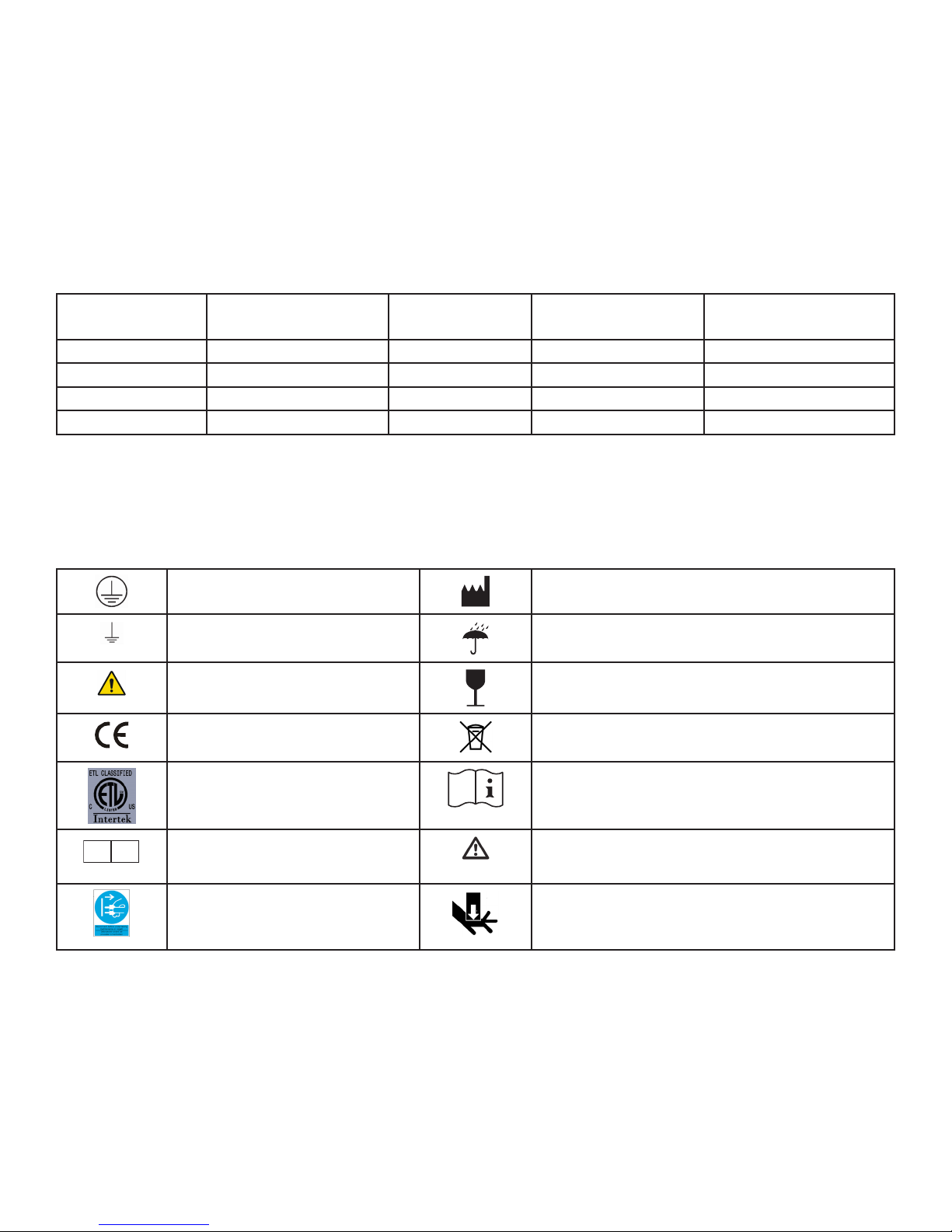
8 DISPOSAL AND KEY TO SYMBOLS
DISPOSAL
Hausted equipment and accessories can be disposed of.
We recommend disassembling and dividing the equipment and components into different
waste groups such as: metal, cable, electronic, recoverable resource and plastic for recycling or
combustion.
Most plastic components are provided with a plastic types code and ber content to aid sorting of
plastic parts.
Product Metal Scrap Cable Scrap Electronic Scrap Plastic Recycling or
Combustion
ESCEYE X X X X
ESDEYE X X X X
EPC250 X X X X
EPD250 X X X X
Info: Lead-acid batteries contained in the controller are recoverable resources and should be
recycled.
KEY TO SYMBOLS
The following symbols are used on Hausted product labels.
Protective Earth Manufacturer
Earth Ground Keep Dry
General Warning Sign Fragile, Handle with Care
CE Mark Electrical and Electronic Equipment
ETL Consult Instructions for Use
EC REP
European Authorized
Representative
Disconnect before Service Pinch Point
Caution
APC-IN-INS-LAB-RevA14 25
www.hausted.com
www.grahameld.com
Page 26
9 APPENDIX
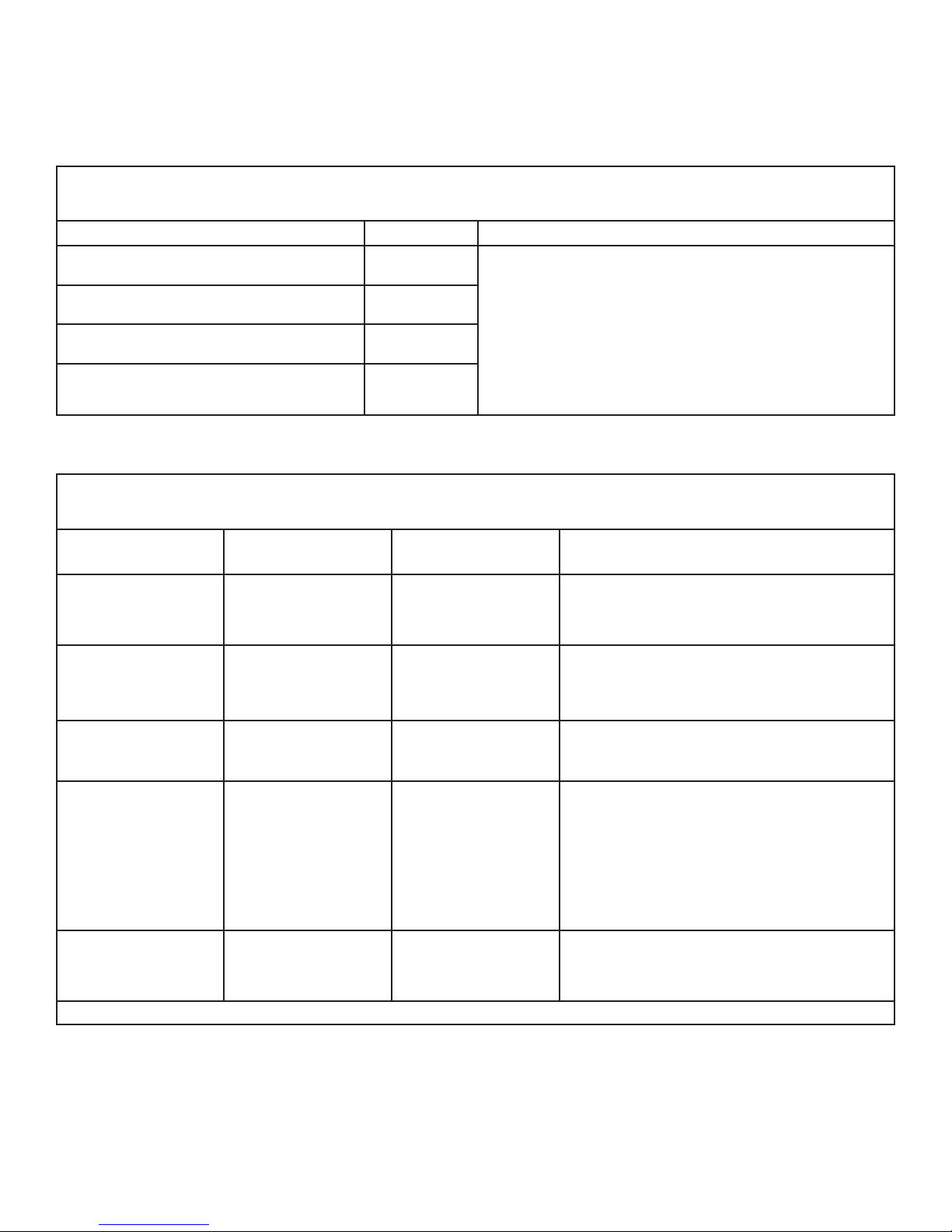
9.1 GUIDANCE AND MANUFACTURER’S DECLARATION —
ELECTROMAGNETIC EMISSIONS
The Hausted APC Series Models and Surgi-Chairs are intended for use in the electromagnetic environment
specied below. The customer or the user of the Hausted APC Series Models and Surgi-Chairs should assure
that it is used in such an environment.
Emissions Test Compliance Electromagnetic Environment — Guidance
RF emissions
CISPR 11
RF emissions
CISPR 11
Harmonic emissions
IEC 61000-3-2
Voltage uctuations/icker emissions
IEC 61000-3-3
9.2 GUIDANCE AND MANUFACTURER’S DECLARATION —
The Hausted APC Series Models and Surgi-Chairs are intended for use in the electromagnetic environment
specied below. The customer or the user of the Hausted APC Series Models and Surgi-Chairs should assure
that it is used in such an environment.
Immunity Test IEC 60601
Test Level
Electrostatic
Discharge (ESD) IEC
61000-4-2
Electrical fast
transient/burst IEC
61000-4-4
Surge IEC 61000-4-5 ±1 kV line(s) to
Voltage dips, short
interruptions and
voltage variations
on power supply
input lines IEC
61000-4-11
Power frequency
(50/60 Hz) magnetic
eld IEC 61000-4-8
NOTE: UT is the a.c. mains voltage prior to application of the test level.
±6 kV contact
±8 kV air
±2 kV for power
supply lines
±1 kV for input/
output lines
line(s)
±2 kV line(s) to earth
<5 % UT (>95 % dip
in UT) for 0,5 cycle
40 % UT (60 % dip in
UT) for 5 cycles
70 % UT (30 % dip in
UT) for 25 cycles
<5 % UT (> 95% dip
in UT) for 5 sec
3 A / m 3 A / m Power frequency magnetic elds should
Group 1 The Hausted APC Series Models and Surgi-Chairs
uses RF energy only for its internal function.
Class A
Class A
Complies
Therefore, its RF emissions are very low and are not
likely to cause any interference in nearby electronic
equipment.
The Hausted APC Series Models and Surgi-Chairs
are suitable for use in all establishments other than
domestic and those directly connected to the public
low-voltage power supply network that supplies
buildings used for domestic purposes.
Compliance Level Electromagnetic Environment —
Guidance
±6 kV contact
±8 kV air
±2 kV for power
supply lines
±1 kV for input/
output lines
±1 kV line(s) to
line(s)
±2 kV line(s) to earth
<5 % UT (>95 % dip
in UT) for 0,5 cycle
40 % UT (60 % dip in
UT) for 5 cycles
70 % UT (30 % dip in
UT) for 25 cycles
<5 % UT (> 95% dip
in UT) for 5 sec
Floors should be wood, concrete or
ceramic tile. If oors are covered with
synthetic material, the relative humidity
should be at least 30%.
Mains power quality should be that
of a typical commercial or hospital
environment.
Mains power quality should be that
of a typical commercial or hospital
environment.
Mains power quality should be that
of a typical commercial or hospital
environment. If the user of the Hausted
APC Series Models and Surgi-Chairs
requires continued operation during power
mains interruptions, it is recommended
that the Hausted APC Series Models
and Surgi-Chairs be powered from an
uninterrupted power supply or a battery.
be at levels characteristic of a typical
location in a typical commercial or hospital
environment.
APC-IN-INS-LAB-RevA14 26
Page 27
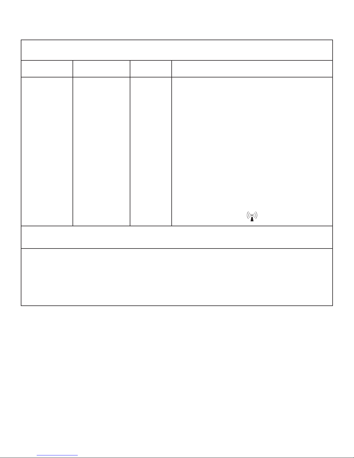
9.3 GUIDANCE AND MANUFACTURER’S DECLARATION —
ELECTROMAGNETIC IMMUNITY
The Hausted APC Series Models and Surgi-Chairs are intended for use in the electromagnetic environment
specied below. The customer or the user of the Hausted APC Series Models and Surgi-Chairs should assure
that it is used in such an environment.
Immunity Test IEC 60601 Test
Level
Conducted RF
IEC 61000-4-6
Radiated RF
IEC61000-4-3
3 Vrms
150 kHz to 80MHz
3 V/m
80 MHz to 2,5 GHz
Compliance
Level
3 vrms
3 V/m
Electromagnetic Environment — Guidance
Portable and mobile RF communications equipment
should be used no closer to any part of the Hausted
APC Series Models and Surgi-Chairs, including cables,
than the recommended separation distance calculated
from the equation applicable to the frequency of the
transmitter.
Recommended separation distance
d = 1.2√P
d = 1.2√P 80 MHz to 800 MHz
d = 2.3√P 800 MHz to 2,5 gHz
where P is the maximum output power rating of the
transmitter in watts (w) according to the transmitter
manufacturer and d is the recommended separation
distance in meters (m).
Field strengths from xed RF transmitters, as
determined by an electromagnetic site survey, should
be less than the compliance level in each frequency
range.
Interference may occur in the vicinity of equipment
marked with the following symbol:
b
NOTE 1: At 80 MHz and 800 MHz, the higher frequency range applies.
NOTE 2: These guidelines may not apply in all situations. Electromagnetic propagation is affected by
absorption and reection from structures, objects, and people.
a
Field strengths from xed transmitters, such as base stations for radio (cellular/cordless) telephones and land
mobile radios, amateur radio, AM and FM radio broadcast and TV broadcast cannot be predicted theoretically
with accuracy. To assess the electromagnetic environment due to xed RF transmitters, an electromagnetic site
survey should be considered. If the measured eld strength in the location in which the Hausted APC Series
Models and Surgi-Chairs are used exceeds the applicable RF compliance level above, the Hausted APC Series
Models and Surgi-Chairs should be observed to verify normal operation. If abnormal performance is observed,
additional measures may be necessary, such as re-orienting or relocation the Hausted APC Series Models and
Surgi-Chairs.
b
Over the frequency range 150 kHz to 80 MHz, eld strengths should be less than 3 V/m.
APC-IN-INS-LAB-RevA14 27
Page 28

9.4 RECOMMENDED SEPARATION DISTANCES BETWEEN PORTABLE AND
MOBILE RF COMMUNICATIONS EQUIPMENT AND HAUSTED APC SERIES
MODELS AND SURGI-CHAIRS
The Hausted APC Series Models and Surgi-Chairs are intended for use in an electromagnetic environment in
which radiated RF disturbances are controlled. The customer or the user of the Hausted APC Series Models
and Surgi-Chairs can help prevent electromagnetic interference by maintaining a minimum distance between
portable and mobile RF communications equipment (transmitters) and the Hausted APC Series Models
and Surgi-Chairs as recommended below, according to the maximum output power of the communications
equipment.
Rated maximum output
power of transmitter (W)
0,01 0.12 0.12 0.23
0,1 0.38 0.38 0.73
1 1.2 1.2 2.3
10 3.8 3.8 7.3
100 12 12 23
For transmitters rated at a maximum output power not listed above, the recommended separation distance d in
meters (m) can be estimated using the equation applicable to the frequency of the transmitter, where P is the
maximum output power rating of the transmitter in watts (W) according to the transmitter manufacturer.
NOTE 1: At 80 MHz and 800 MHz, the higher frequency range applies.
NOTE 2: These guidelines may not apply in all situations. Electromagnetic propagation is affected by
absorption and reection from structures, objects, and people.
Separation distance according to frequency of transmitter (m)
150 kHz to 80 MHz
d = 1.2√P
80 MHz to 800 MHz
d = 1.2√P
800 MHz to 2,5 GHz
d = 2.3√P
APC-IN-INS-LAB-RevA14 28
Page 29

10 INDEX
A
Accessories, optional 19
Accessories, optional, list 23
Advisory 4
APC / Surgi-Chair specications 9
A word from GF Health Products, Inc. 4
B
Back section, lowering 14
Back section, raising 14
Battery replacement instructions 21
Brakes, releasing 12
Brakes, steering, applying 12
Brakes, steering, releasing 12
Braking and steering operation 12
C
CAUTION labels 11
CAUTION statement, signicance 5
Cleaning 22
D
DANGER statement, signicance 5
DANGER / WARNING / CAUTION / NOTICE Summary 5
Disposal 25
E
Electrical specications (EPC / ESC) 9
Electrical specications (EPD / ESD) 9
Electric control locations 13
Electromagnetic emissions, guidance and manufacturer’s
declaration 26
Electromagnetic immunity, guidance and manufacturer’s
declaration 27
Environmental conditions 8
F
Features 11
Footrest, adjustable 16
Footrest, repositioning 16
Foot section adjustment 14
Foot section, lowering 14
Foot section, raising 14
H
Headrest, adjusting 18
Headrest, ESCEYE/ESDEYE 18
Height, lowering 14
Height, raising 14
I
Indications for Use 4
Info statement, signicance 5
IV rod, #18 (optional accessory), installing 19
L
Limited warranty 24
Low battery light 13
Lubrication 22
N
NOTICE statement, signicance 5
O
Operating instructions 9
P
Patient tray (optional accessory), installing 20
Pendant control location 13
Plug location 13
Preventive maintenance for the user 22
PROPER OPERATION labels 11
Q
Quick drop activation 15
R
Rail, repositioning 17
Rails, hinging 17
Restraint straps (optional accessory), using 20
S
Safety statements, signicance of 5
Service information 4
Side tray, optional accessory, installing 19
Symbol key, Hausted product labels 25
T
Troubleshooting guide 21
U
Uncrating instructions 8
Unpacking instructions 8
W
WARNING labels 11
Warnings 5
WARNINGS and CAUTIONS, list 5
WARNING statements 5
WARNING statement, signicance 5
Warranty, limited 24
Wrist rest (optional accessory), adjusting 19
Wrist rest (optional accessory), mounting 19
APC-IN-INS-LAB-RevA14 29
Page 30

www.hausted.com
www.grahamfield.com
 Loading...