

Hausmann Powermatic 1440 Installation & Operation Instructions
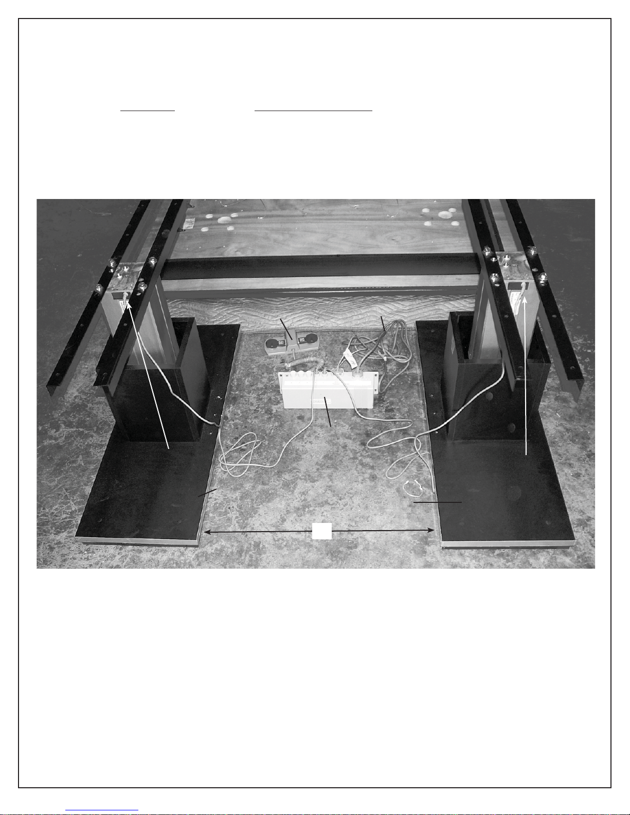
Step 1
Place (2) Base Assemblies (A1 and A2) parallel to each other as shown in place on the fl oor in the location where
you want to install the mat platform.
“X” Distance between base plates varies as follows:
Size of Top Distance Between Plates
6’ x 8’ 52”
5’ x 7’, 4’ x 7’ 45”
4’ x 6’ 39 3/8”
Underside of top (on blanket)
A1 Actuator Wire
(Hard Connection)
Base
Assembly
A1
Foot Control
Control Box
X
110V Power
Cord
Base
Assembly
A2
A2 Actuator Wire
(Hard Connection)
2
rev. 09.09.2009 cjr ©2009 HAUSMANN INDUSTRIES, INC.

Step 2
Before doing any assembly, pre-test motors. Plug power cord into grounded wall outlet. The electrical rating for Series
1440 is 110V AC, 60Hz, 1.6 Amps. The 3-prong hospital grade grounded plug must be plugged in 3-pronged,
grounded, non-isolated, correctly polarized 110V AC receptacle. Failure to do so could result in personal
injury or damage to equipment.
A. Step on UP button and elevate unit about 5” - 6”.
B. Step on DOWN button and lower down as far as it will go.
C. Step on UP button and elevate up to maximum height.
NOTE: During the pre-testing, the green light on the Control Box should be on to indicate there is power to the control
box. If for any reason there is no response, see the trouble shooting guide on page 8 for possible problems - most
common of which is loose plug connections into control box.
You have completed initial test. Unplug power cord from power source as electrical power is not needed for remainder of assembly.
Detail of Control Box
110V Power
Cord
Port for
Actuator A1
Port for
Actuator A2
110 V Power
Cord
Underside of Control Box
Foot Control Cord and Plug
3
rev. 09.09.2009 cjr ©2009 HAUSMANN INDUSTRIES, INC.
Green Light
 Loading...