

Page 1
Model # 1560-65-036
PART
QTY
DESCRIPTION
A 1 Base
C 1 4-Step Stair Case
D 1 3-Step Stair Case
E 2 Straight Handrails
F 2 Medium Handrails
G 2 Long Handrails
H 4 52” Uprights for Straight Handrails
I 2 47¼” Uprights for Handrails
J 2 46½” Uprights for Handrails
K 2 40 ¼” Uprights for Handrails
L 2 37½” Uprights for Handrails
Tools Required:
Allen Wrench (included)
Philips Screw Driver
Product Specifications
Model
Length
Width
Height
(Platform)
Weight Capacity
1580 (Straight)
91”
36”
18”
350 lbs
1580 (Corner)
36”
18”
350 lbs
HARDWARE BAG
PART
QTY
DESCRIPTION
P
8
3¼” Allen Hex Head Bolt
Q
12
2 3/8 ” Allen Hex Head
Bolt
R
32
45mm Pan Head/Philips screw
S
32
16mm Barrel Bolt
T
1
4 mm Allen Wrench
U
32
Flat Washer
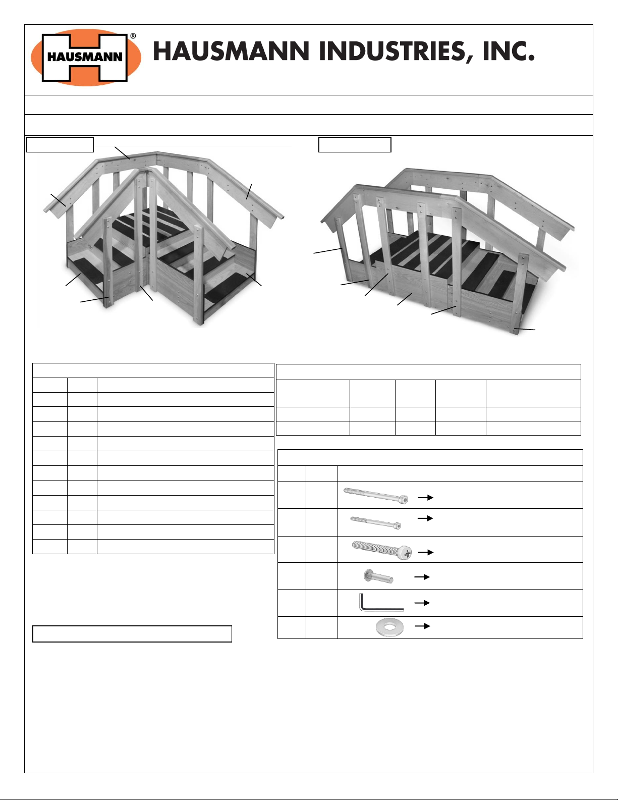
Figure 1: Model #1580 Corner Set-Up
Figure 2: Model #1580 Straight Set-Up
Straight Set-Up
H c D E F G I A J
L
Corner Set-Up
J K K
2 People Required for Assembly
Installation/Operation Instructions
Model # 1580 – ADA Convertible “Space Saver” Staircase
A) INSTALLATION INSTRUCTIONS:
1. Unpack all contents from shipping carton; confirm correct parts & quantity.
2. Place all the parts in a desired location for assembly. Model # 1580 can be assembled in two configurations (Straight or
Corner).
3. Layout the base ‘A’ and Step sections ‘C’ or ‘D’ by mounting the wooden ‘cleat’ on opposite sides for a Straight setup or
next to each other for a Corner setup.
Rev. 102413 aj Page 1 of 3 ©2013 HAUSMANN INDUSTRIES, INC.
Page 2
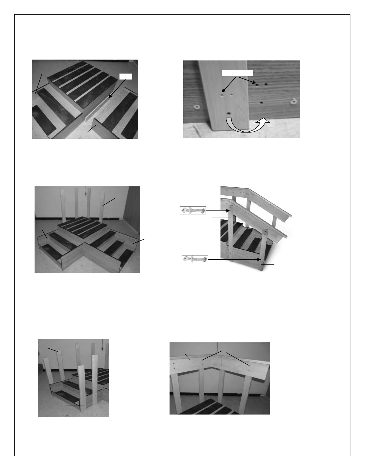
Figure 5: Base with Uprights ‘H’
Figure 6: 4-Step Stair with uprights
Figure 6: 3-Step Stair with uprights
Figure 3: Base with Step sections
Figure 4: Dots on Upright & Steps
Figure 7: Straight Handrails ‘E’
Dots to match
Cleat
D C D C H I L
E
S
J
K
4. Lift the Step sections up and over the “cleat” to set them into place as shown in Figure 3.
NOTE: Each upright and step section is machined with an indexing mark to note where each upright and handrail are
supposed to be installed. A series of 1, 2 or 3 dots on the uprights will match up to the same dots on the outside of the
step section. Attach the uprights so that the dots folds on top of each other as shown in Figure 4.
5. Attach uprights ‘H’ on the open ends of the base ‘A’ using Hex head bolts ‘P’ and Allen key, with the dots facing inwards
as shown in Figure 5. (It may require to remove (2) bolts from the upper mounting positions on the center platform to
attach the uprights or position the step sections). HAND TIGHTEN ONLY!
6. Attach uprights (‘I’, & ‘L’ respectively) onto the 4-Step section, by matching up the dots on the upright with step
section using four Hex head bolts ‘Q’ on the bottom of the uprights and two on the top of the 3rd step, and two Pan
Head/Philips screw ‘R’ with Flat Washer ‘U’ and Barrel Bolt ‘S’ on the rest as shown in Figure 6.
7. Attach uprights (‘J’ & ‘K’ respectively) onto the 3-Step section using four Hex head bolts ‘Q’ on the bottom of the
uprights and two on the top of the 2nd step and two Pan Head/Philips screw ‘R’, Flat washer ‘U’ and Barrel Bolt ‘S’ on
the rest as shown in Figure 7.
8. Insert the Barrel Bolt ‘S’ into the straight handrails on the opposite side of the dots as shown in Figure 7.
Rev. 102413 aj Page 2 of 3 ©2013 HAUSMANN INDUSTRIES, INC.
Page 3
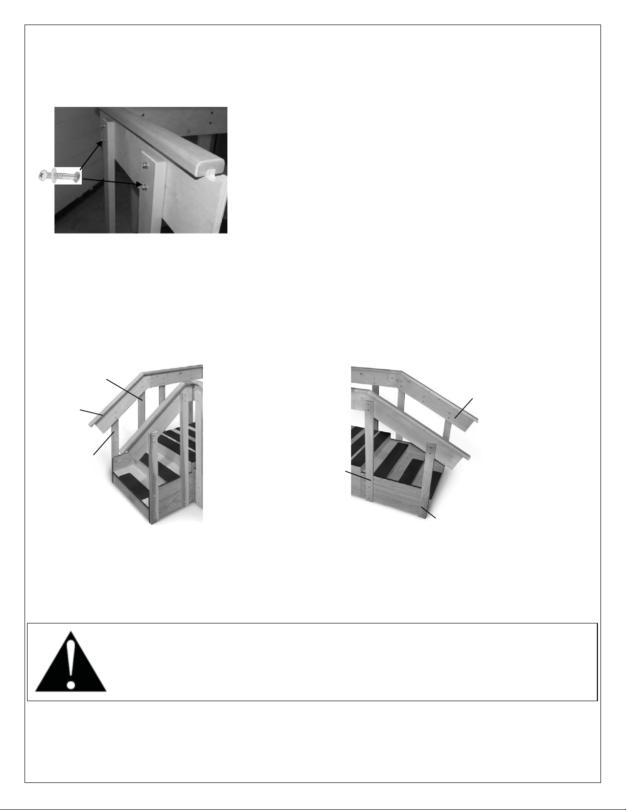
Figure 8: Straight Handrails attached
Figure 9: Medium Handrail ‘F’
Figure 10: Long Handrail ‘G’
J
K I L F G
CAUTION: PREVENTATIVE MAINTENANCE REQUIRED
1. Inspect hex bolts and other mechanical fasteners periodically. Tighten bolts, screws or connections if loose (Tighten until
snug, but do not overtighten). Failure to do so may result in serious injury.
2. Do not use if any loose fasteners are found.
3. Discontinue use of any product that is NOT in proper working order until situation is rectified. Failure to do so may result in
serious injury.
9. Attach the straight handrails ‘E’ over the Base ‘A’ on the inside part of the uprights so that Barrel bolts on the handrails
should be facing inwards using Pan Head/Philips screw ‘R’ with Flat washer ‘U’ as shown in Figures 8 & 7. At this point
loosely fit the handrail on the uprights.
NOTE: Each Handrail is produced with either a ‘hook’ or a ‘cup that are designed to ‘lock’ into each other when
assembled. They also have an inner and outer face, so it is important that they are installed in the correct location.
10. For the corner setup the corner is ‘locked’ together with the ‘hook’ & ‘cup’ fitting as shown in Figure 7 and for the
straight setup the remaining handrails can only be setup one way for correct assembly.
11. Insert the Barrel bolts ‘S’ in each of the medium and long handrails ‘F’ & ‘G’ respectively the same way it was inserted
in straight handrails.
12. Attach the Medium handrails ‘F’ on the inside part of the ‘J’ & ‘K’ uprights so that Barrel bolts ‘S’ on the handrails
should be facing inwards using Pan Head/Philips screw ‘R’ with Flat washer ‘U’ as shown in Figures 9.
NOTE: Fit the ‘hook’ or ‘cup’ into the handrail next to it. Once all the handrails are installed, tighten all screws and bolts to
secure the structure.
13. Attach the Long Handrails ‘G’ on the inside part of the ‘I’& ‘L’ uprights so that Barrel bolts ‘S’ on the handrails should be
facing inwards using Pan Head/Philips screw ‘R’ with Flat washer ‘U’ as shown in Figures 10.
NOTE: Fit the ‘hook’ or ‘cup’ into the handrail next to it. Once all the handrails are installed, tighten all screws and bolts to
secure the structure.
Rev. 102413 aj Page 3 of 3 ©2013 HAUSMANN INDUSTRIES, INC.
 Loading...