

Page 1
Page 2
Step 1
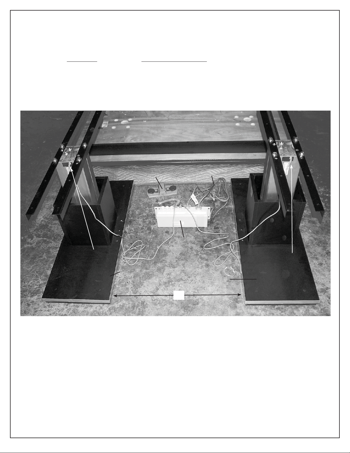
Place (2) Base Assemblies (A1 and A2) parallel to each other as shown in place on the fl oor in the location where
you want to install the mat platform.
“X” Distance between base plates varies as follows:
Size of Top Distance Between Plates
6’ x 8’ 52”
5’ x 7’, 4’ x 7’ 45”
4’ x 6’ 39 3/8”
Underside of top (on blanket)
A1 Actuator Wire
(Hard Connection)
Base
Assembly
A1
Foot Control
Control Box
X
110V Power
Cord
Base
Assembly
A2
A2 Actuator Wire
(Hard Connection)
2
rev. 09.09.2009 cjr ©2009 HAUSMANN INDUSTRIES, INC.
Page 3
Step 2
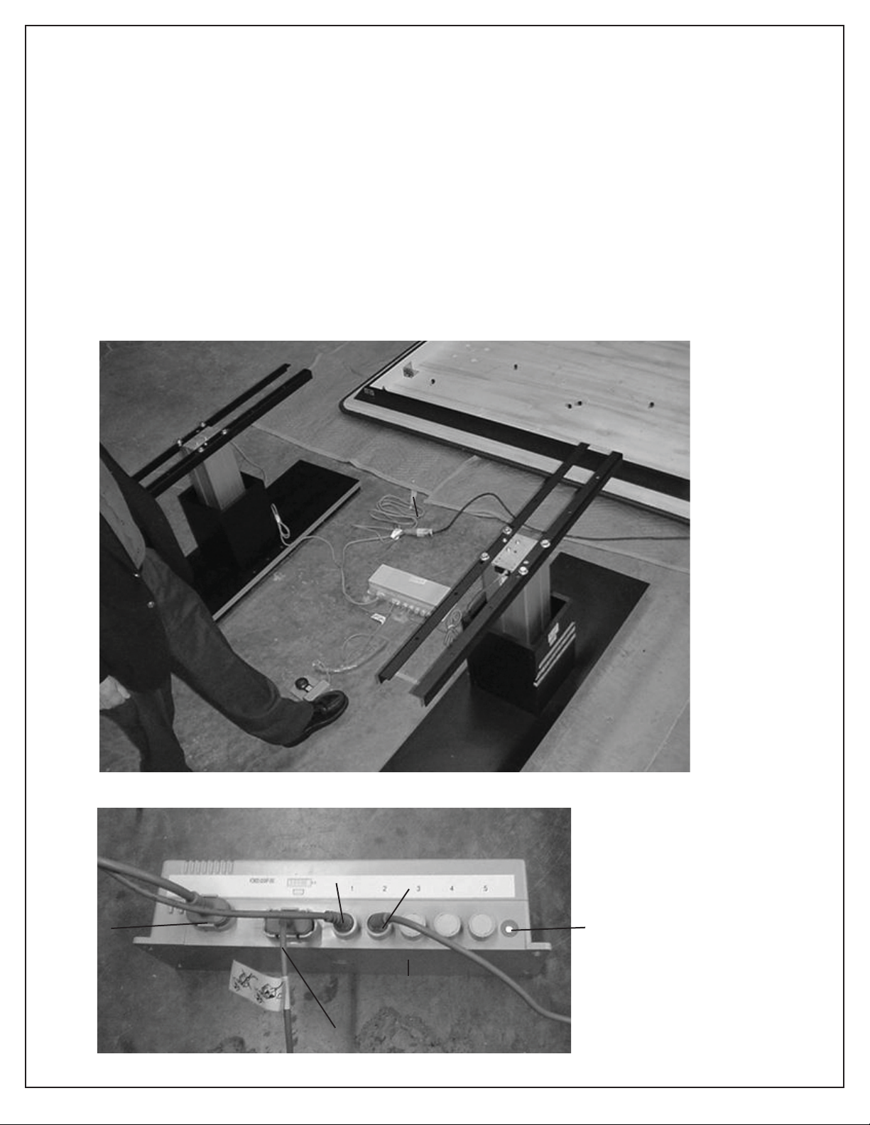
Before doing any assembly, pre-test motors. Plug power cord into grounded wall outlet. The electrical rating for Series
1440 is 110V AC, 60Hz, 1.6 Amps. The 3-prong hospital grade grounded plug must be plugged in 3-pronged,
grounded, non-isolated, correctly polarized 110V AC receptacle. Failure to do so could result in personal
injury or damage to equipment.
A. Step on UP button and elevate unit about 5” - 6”.
B. Step on DOWN button and lower down as far as it will go.
C. Step on UP button and elevate up to maximum height.
NOTE: During the pre-testing, the green light on the Control Box should be on to indicate there is power to the control
box. If for any reason there is no response, see the trouble shooting guide on page 8 for possible problems - most
common of which is loose plug connections into control box.
You have completed initial test. Unplug power cord from power source as electrical power is not needed for remainder of assembly.
Detail of Control Box
110V Power
Cord
Port for
Actuator A1
Port for
Actuator A2
110 V Power
Cord
Underside of Control Box
Foot Control Cord and Plug
3
rev. 09.09.2009 cjr ©2009 HAUSMANN INDUSTRIES, INC.
Green Light
Page 4
Step 5
3
4
Place upholstered top over base assembly.
Place underside of upholstered top so the exposed bolt heads on each actuator fi t into (4) routed holes on each side
of wood underside of top and (3) holes in black angle irons line up with the (8) pre-drilled holes in underside.
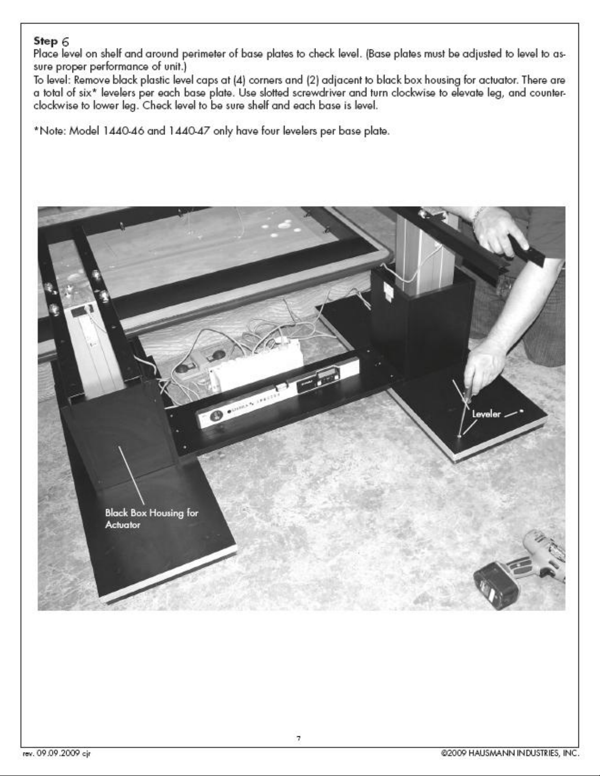
Secure each black angle iron to subtop with (4) 1/4” - 20 x 7/8” machine screws “D” into pre-threaded t-nuts in
underside of top. Total of sixteen 1/4” - 20 x 7/8” machine screws needed for all (4) black angle irons.
Upholstered top placed on base assembly.
Hole 1
Hole 2
Hole 3
Hole 4
See page 7 for
attachment of wires
See page 7 for
attachment of control
box (next step)
6
rev. 09.09.2009 cjr ©2009 HAUSMANN INDUSTRIES, INC.
Page 5
Step 6
4
5
5
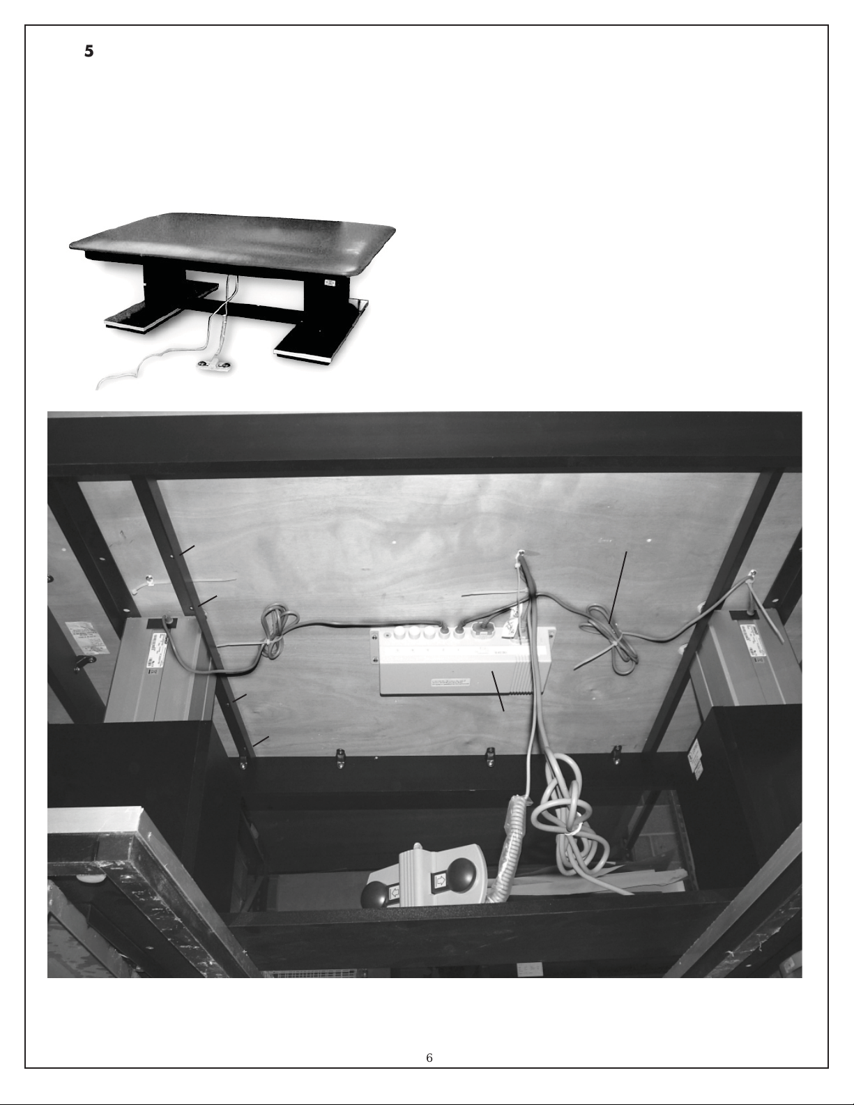
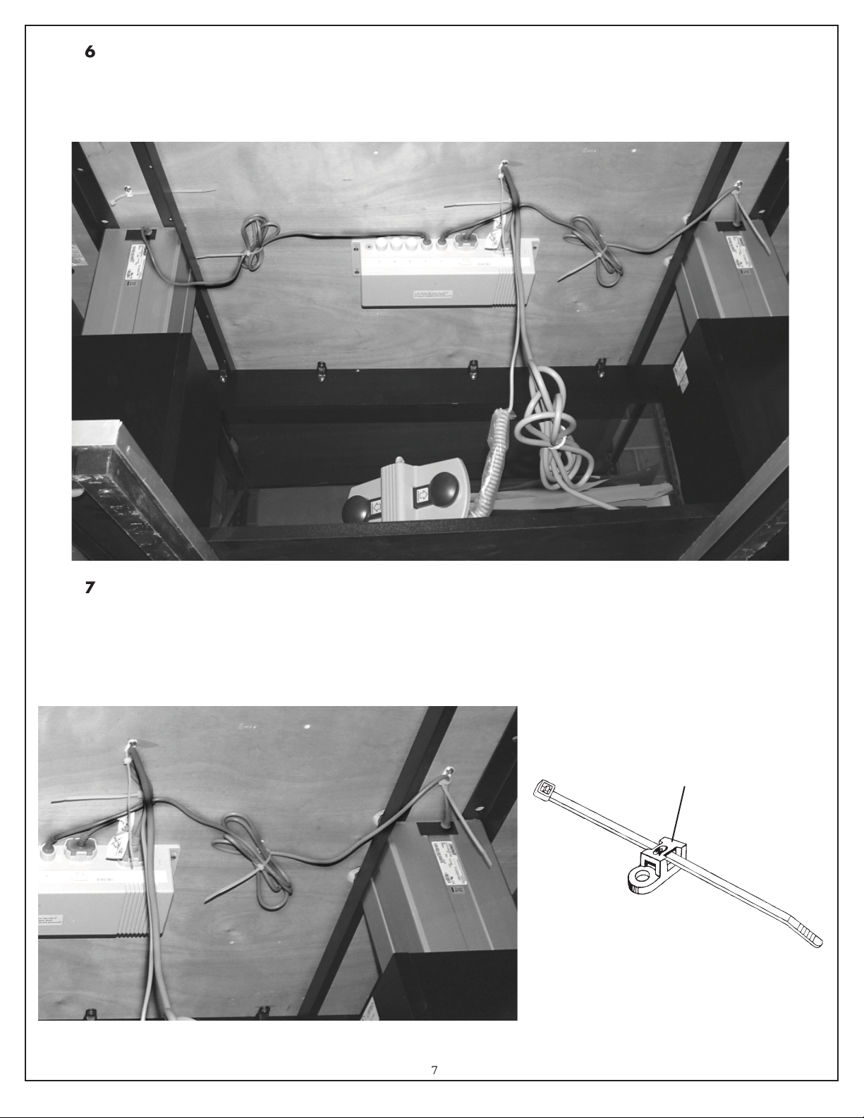
Attach control box to underside of top with keyhole attachment. Tighten down keyhole screws with phillips head
screwdriver to secure control box to underside. Secure power cord and footswitch wire together to underside of top
with two cable ties as shown.
Step 7
Use cable zip ties to properly secure actuator wire to underside of top. First secure wire with cable tie closest to
actuator then bundle excess wire and secure with cable tie located between base assembly and control box. Repeat
procedure for Actuator A2.
Cable Zip Tie
7
rev. 09.09.2009 cjr ©2009 HAUSMANN INDUSTRIES, INC.
Page 6
Step 3
5
6
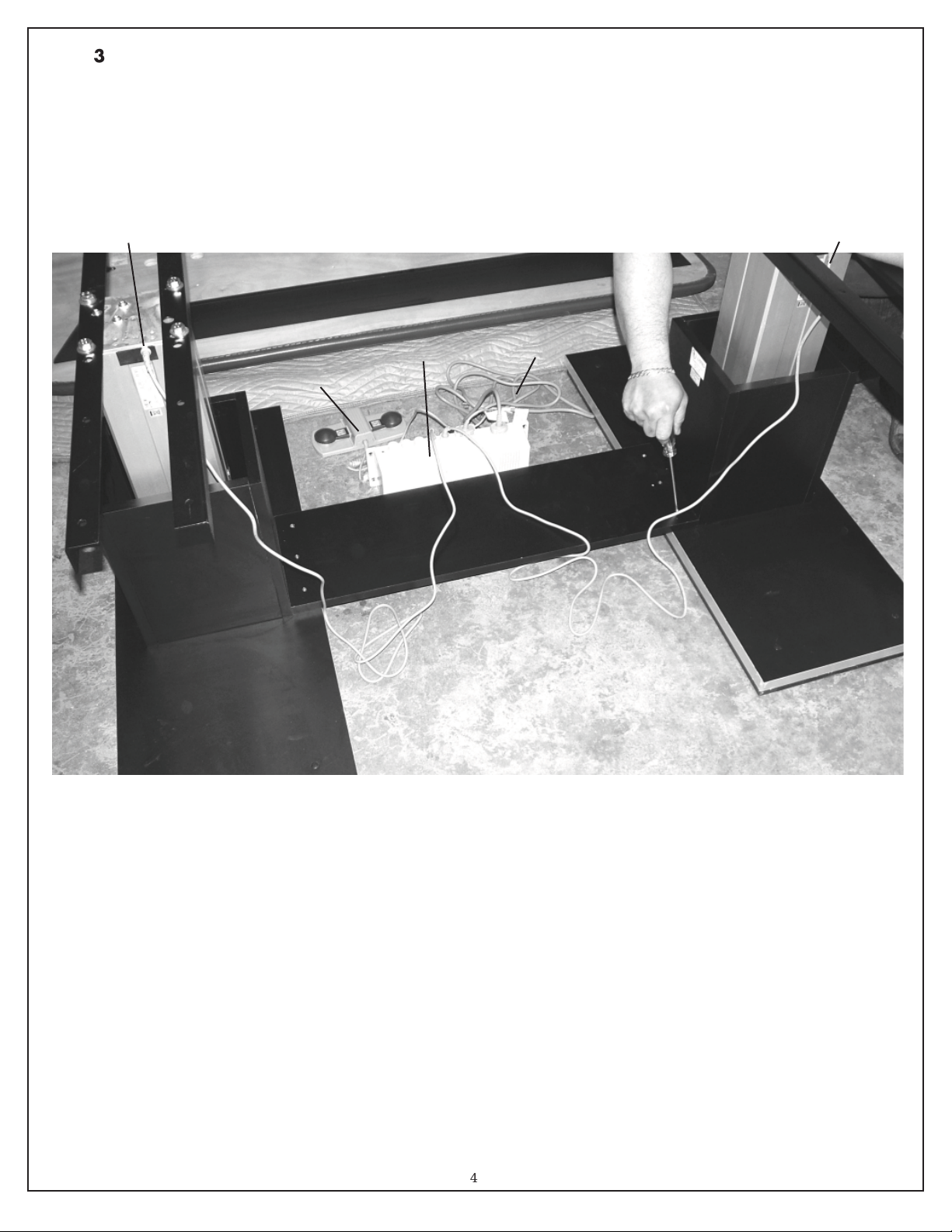
Place Shelf “C” between A1 and A2 Base Assemblies. Both ends of shelf must rest on base plate and butt-fi t to black
“box” around actuator.
Secure shelf with (3) 1 3/4” x #8 fl at head phillips head screws per each side (total of six screws needed). Apply
pressure as holes are not pre-drilled in base plate.
Cord from Actuator A1 Cord from Actuator A2
A1
Foot Control
Shelf “C”
Control Box
110V Power
Cord
A2
4
rev. 09.09.2009 cjr ©2009 HAUSMANN INDUSTRIES, INC.
Page 7
Page 8
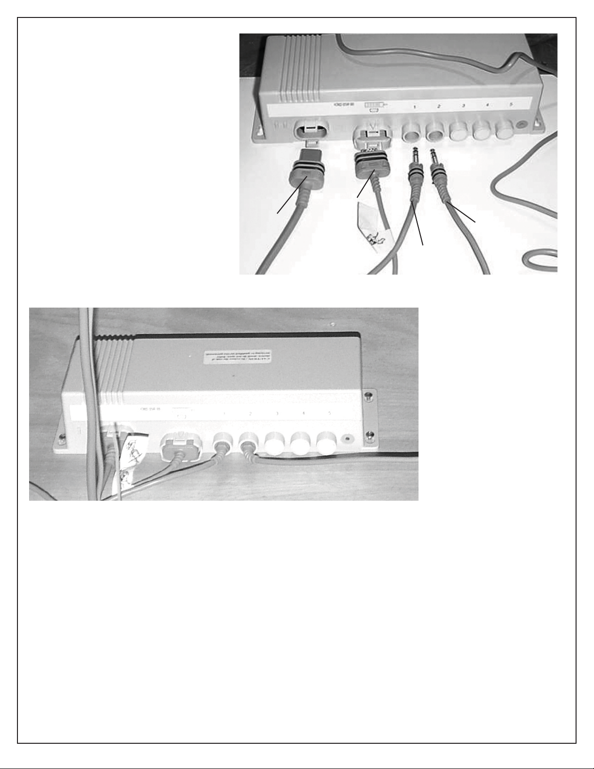
Detail of Control Box Connections
in case of replacement of any components
IMPORTANT NOTE: Actuator plug must
be fully inserted with top and bottom
notches on plug at 12 o’clock and 6
o’clock position. After fully inserting actuator’s plug, you must turn plug clockwise 1/8th of a turn to lock into position.
(To unlock push in and turn plug 1/8th of
a turn counterclockwise is notch of plug
lines up with 12 o’clock hash mark at top
of round ports.
This is most frequent problem in that plug
110V
Power
Plug
Foot
Control
Plug
is sometimes plugged in at 12 o’clock but
not fully inserted and not turned 1/8th
turn to right to lock.
Actuator A1
Plug-in
Detail of Control Box Connections with all plugs inserted into place for operation.
Actuator A2
Plug-in
Trouble Shooting
Symptom: System not working after all connections are made and unit is plugged into wall outlet.
1. Is the green light on upper left side of control box on? If not, there is not power to control box. Verify that electrical cord is plugged into control box and plugged into wall outlet.
If unit still does not work, verify that the wall outlet is active by plugging in another appliance or lamp. Could be
“shut-down” due to ground-fault de-activation or faulty outlet.
2. Verify that both left and right actuator’s plugs are properly plugged into ports 1 and 2 on control box.
Actuator plug must be fully inserted, with top and bottom notches on plug at 12 o’clock and 6 o’clock positions.
After fully inserting actuator’s plug, you must turn plug clockwise 1/8th of a turn to lock into position.
3. When you depress foot control, you should hear a click in control box to refl ect active operation of foot control.
If foot control does not cause clicking sound in control box then it could be a faulty foot control. If you have a
second unit of current design that is working, then swap “good” foot control for “bad” one to see if that corrects
the problem. If you get a clicking sound then foot control is probably active (foot control triggers relay in box).
4. If green light is on in control box and foot switch is operational and there is no clicking sound when foot control
is depressed it could be a faulty relay in control box, hence replace control box.
5. Check all wires and connections to make sure wires are nut cut and all connections are in fi rmly and operative.
8
rev. 09.09.2009 cjr ©2009 HAUSMANN INDUSTRIES, INC.
Page 9
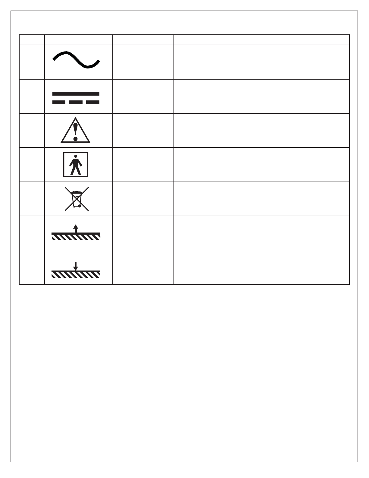
Table of Symbols
Please join Hausmann’s effort to reduce paper use and keep the planet green by using our paperless Warranty
Registration form. Visit www.hausmann.com and click on Warranty Registration. If you do not have web access or
prefer the form be mailed or faxed to you, please call Hausmann Customer Service.
As of January 1, 2010, we will no longer include the paper based forms, please visit the online link to fill in your
Warranty Form.
No. Symbol IEC Publication Description
1 417-5032 Alternating Current
2 417-5031 Direct Current
3 348 Attention, consult ACCOMPANYING DOCUMENTS
4 417-5333
Type BF Applied Part
878-02-05
5 N/A Dispose of properly
6 N/A Table movement, UP
7 N/A Table movement, DOWN
Electrical Specifi cations:
Input: 120 VAC / 1ph / 60 Hz / 2.5 Amps Max
Output: 24 VDC / 6 Amps
Environmental Conditions - Normal Operations:
Ambient Temperature: +10 to +40°C (+50 to +104°F)
Air Humidity: Max. 85%
Environment Conditions - Storage / Transportation:
Ambient Temperature: -20 to +60°C (-4 to +140°F)
Air Humidity: Max. 95%
Recommended Cleaning Solution and Procedure:
UNPLUG UNIT BEFORE ATTEMPTING ANY CLEANING AND/OR DISINFECTING.
Infective material should be removed by scrubbing with an approved germicidal solution. After scrubbing, rinse with
a wet cloth and allow to dry.
rev. 09.09.2009 cjr ©2009 HAUSMANN INDUSTRIES, INC.
9
Page 10
HAUSMANN INDUSTRIES, INC.
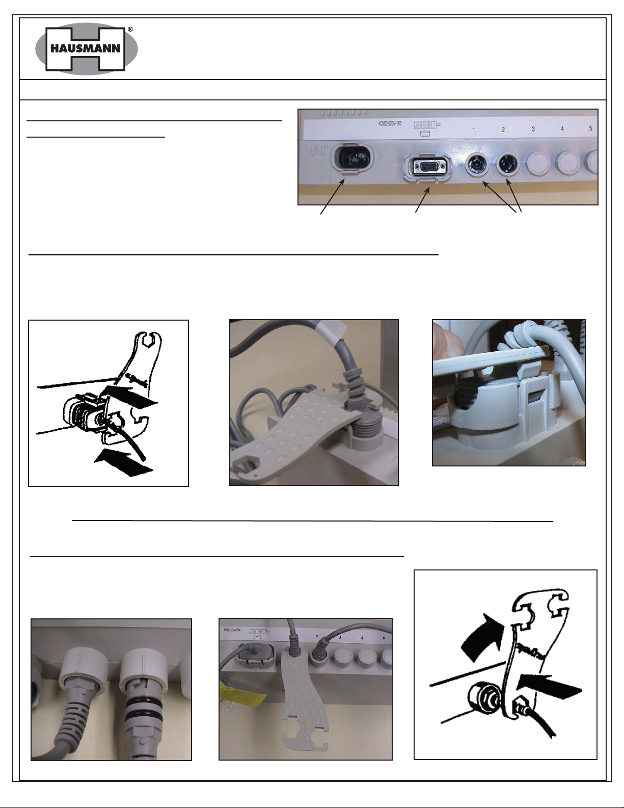
Model 1440 - Special Wrench Instructions
ATTACHING POWER PLUG AND FOOT SWITCH
PLUG TO CONTROL BOX
When attaching Power Plug and Foot Switch Plugs
to Control Box ensure that the plugs are inserted
in the correct position to prevent damage to the
control unit and /or the plug. (Note plug shape.)
Power Plug Port Foot Switch Port Actuator Port
DETACHING POWER PLUG AND FOOT SWITCH PLUG FROM CONTROL BOX
The two lines may only be detached from the control box by means of special plastic wrench with which the
brackets can be separated, by pulling the plug (see illustrations). The brackets can break if they are opened too
wide. Strain relief and watertightness are no longer guaranteed. Note: Some force is still required to remove plug
from Control Box.
ATTACHING AND DETACHING ACTUATOR PLUGS TO CONTROL BOX
The 1/4” plugs must be inserted into the control unit until the O-rings are
no longer visible, and turned approx 30° to the right as far as the stop by
means of special plastic wrench to lock. If this is not done, strain relief and
water tightness are not guaranteed.
rev. 09.09.2009 cjr ©2009 HAUSMANN INDUSTRIES, INC.
 Loading...