

Page 1
Product Specifications
Model #
Length
Width
Height
Weight Capacity
1427-46
6’
4’
20” – 30”
750 lbs
1427-47
7’
4’
20” – 30”
750 lbs
1427-57
7’
5’
20” – 30”
750 lbs
1427-68
8’
6’
20” – 30”
750 lbs
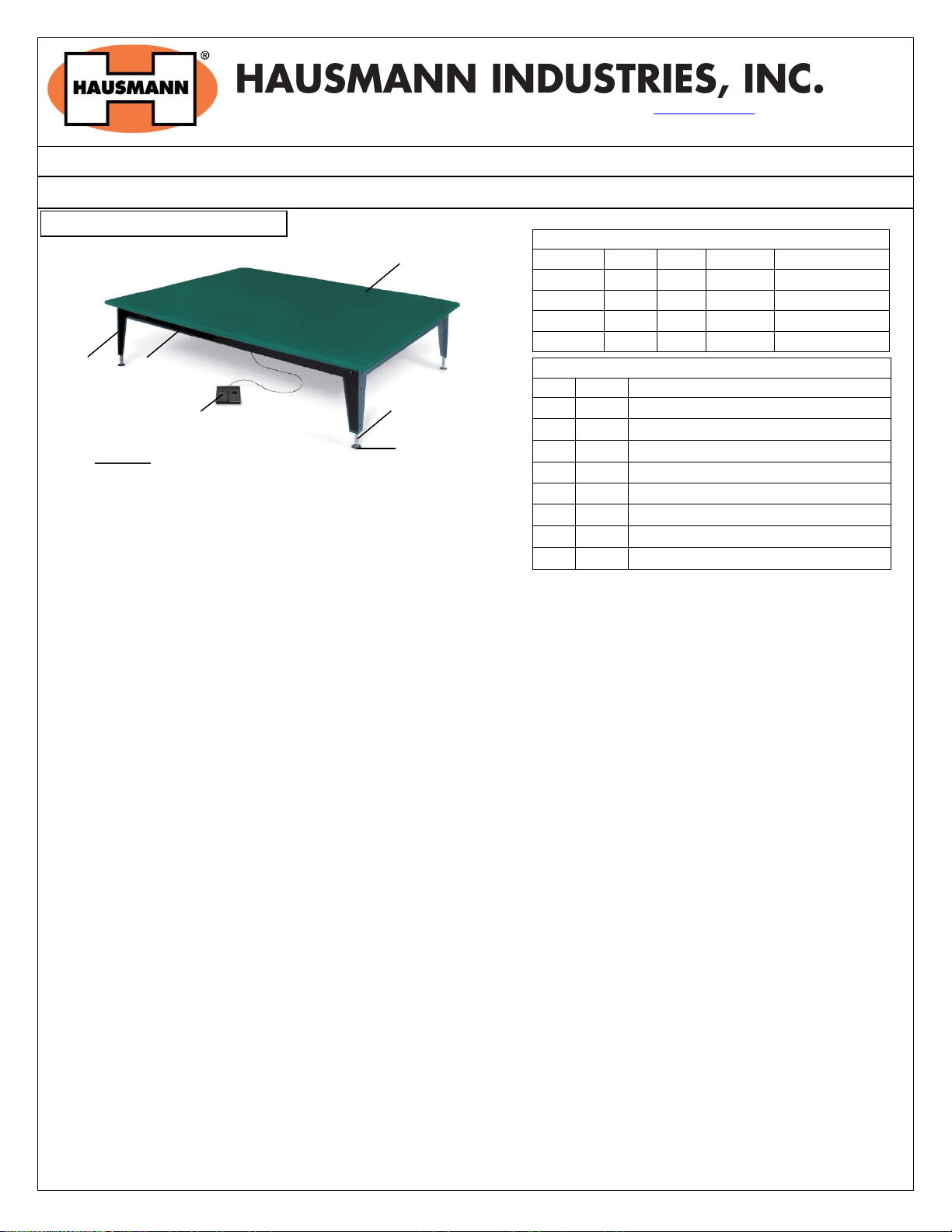
Part Lists
Part
Qty
Description
A 1 Upholstered Top
B
4
Black Steel Aprons (2 long, 2 short)
C
4
Corner Steel Legs
D 4 Hydraulic Lift Cylinder/Legs
E
1
115 V Motor/Hydraulic Pump Assm.
F
4
Adjustable Leg Levelers
G 1 Foot Control, 12V DC with 6’ cord
H 1 Control Box
Platform Ships Fully Assembled
Figure 1: Mat Platform
A
C
B D F
G
130 Union St • Northvale NJ 07647 USA • Tel: (201) 767-0255 • Fax: (201) 767-1369 • www.hausmann.com
A) INSTALLATION INSTRUCTIONS
Installation/Operation Instructions
Model 1427 – Bariatric Electric Mat Platform
1. Remove all packaging material from the platform.
2. Plug the power cord into a properly grounded 120 Volt AC
outlet and follow the procedure outlined in the
precautionary instructions.
Leveling the Platform:
1. Place the table in position before leveling.
2. Use adjustable wrench to rotate leg levelers for height adjustment.
B) OPERATING INSTRUCTIONS
Duty cycle on/off Int. 2 min./ 18 min.
1. Raise the platform by gently pressing the up arrow on the footswitch.
2. Lower the platform by gently pressing the down arrow on the footswitch.
C) MAINTENANCE
In the event it becomes necessary to replace the foot switch or power cord, make certain that the component is
connected properly and the locking tabs on the motor snaps in place.
For assistance please call Hausmann Industries at (201) 767-0255, press 5 for Customer Service. We may request
purchase details (product, date purchased, dealer) to better assist you.
Rev. 072514 aj Page 1 of 7 ©2013 HAUSMANN INDUSTRIES, INC.
Page 2
®
Movotec
Q-Drive Motorized Lift Systems
Refill Instructions
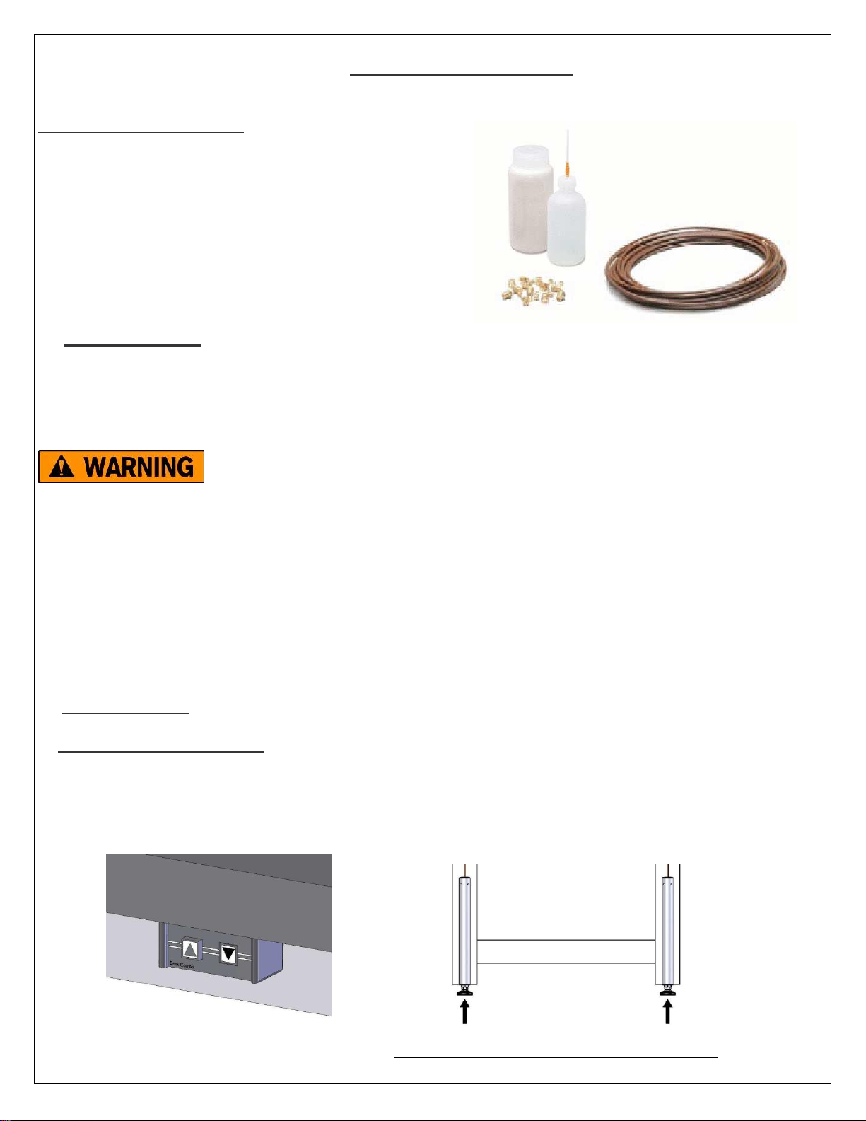
Movotec® Refill Kit Contents
Movotec® Refill Instructions
Movotec® NT15 Hydraulic Fluid MSDS
(0.5) Liters (16.9 oz.) of Movotec® NT15 Hydraulic Fluid
Filler Bottle
Filler Bottle Cap
Filler Bottle Needle
(10) Meters (32.8 ft.) of Movotec® Flexible Hydraulic Tubing
(12) Ferrules
(12) Compression Nuts
1.0 Safety Instructions
This document contains safety and user service instructions for refilling a Movotec® Q-Drive Motorized Lift System. Suspa
®
Incorporated is not responsible for any alteration or deviation from these instructions resulting in property damage, personal
injury or death.
FAILURE TO FOLLOW THE INSTRUCTIONS IN THIS DOCUMENT COULD
RESULT IN FIRE, PROPERTY DAMAGE, ELECTRC SHOCK, PERSONAL
INJURY OR DEATH.
The instructions in this document are intended to be used in conjunction with the Movotec® Refill Kit. The Movotec® NT15
hydraulic fluid contained in this kit is specially formulated for the improved performance of our lift systems. DO NOT, FOR
ANY REASON, USE ANY FLUID OTHER THAN MOVOTEC® NT15 HYDRAULIC FLUID WHEN REFILLING A MOVOTEC® LIFT
SYSTEM.
READ ALL INSTRUCTIONS BEFORE ATTEMPTING TO REFILL A MOVOTEC® LIFT SYSTEM.
2.0 System Preparation
2.1 Motorized System Preparation.
Lower the system by holding “down” arrow button on the switch. Continue holding “down” arrow button until all lift
cylinders have reached their fully retracted position. Remove finger from the switch. Then, press and hold “down” arrow
button again. After approximately 5 seconds the system will begin to retract until the “zero” position is reached. The system
is now fully retracted.
COMPRESS CYLINDERS COMPLETELY
Rev. 072514 aj Page 2 of 7 ©2013 HAUSMANN INDUSTRIES, INC.
Page 3
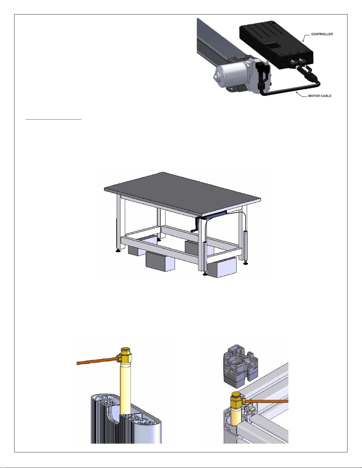
Once the system has reached the “zero” position, unplug power
cord from the power outlet. Then disconnect motor cable from
controller (keep cables plugged in to back of motor drive).
2.2 Cylinder Preparation
To properly refill a cylinder, the load must be removed from all cylinders and/or the workstation. For Movotec® “Bolt-On” lift
systems, this can be achieved by lifting the entire workstation off of the floor with a lift truck or pallet jack. Blocks can be
used to stabilize the workstation during the refill procedure.
For Movotec® ATU and Corner Leg systems, lift cylinder(s) that are to be refilled must be removed from their corresponding
support leg. Movotec® ATU lift systems will require external retaining ring pliers to remove the 13mm retaining ring from the
top of the lift cylinder. For Movotec® Corner Leg lift systems, a T25 torx driver will be required to remove (4) torx screws at
the top of the corner leg support housing. Additionally, external retaining ring pliers will be required to remove a 13mm
retaining ring and upper cap from the top of the lift cylinder.
ATU Cylinder Removal Corner Leg Cylinder Removal
Rev. 072514 aj Page 3 of 7 ©2013 HAUSMANN INDUSTRIES, INC.
Page 4
2.3 Pump Preparation
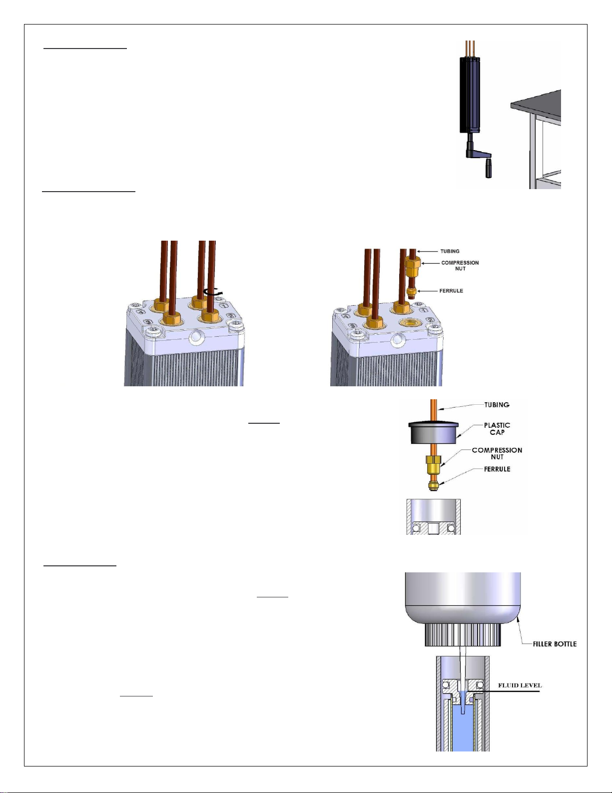
Detach pump from work surface. Orient and secure pump in an upright position to prevent
fluid loss during the refill procedure. Be careful not to stretch, kink, or damage the hydraulic
tubing and connections.
Crank Driven Pump (Shown in Upright Position)
3.0 Tubing Disconnection
To disconnect tubing from pump, unscrew and remove the compression nut, ferrule, and tubing assembly which corresponds
with the lift cylinder to be refilled.
To disconnect tubing from cylinder, unscrew and remove compression nut,
ferrule, and tubing assembly from cylinder port. NOTE: CB cylinders will require
the removal of plastic cap to expose the compression nut.
CB Cylinder Shown
4.0 Refill Procedure
To refill the pump, fill open port with Movotec® NT15 Hydraulic Fluid to level
indicated below using the filler bottle with needle. NOTE: The pump element will
not fill properly if the filler bottle needle is not inserted past the smallest opening
in the port as shown.
To refill a top-ported cylinder, slowly pull cylinder rod to an extended length of
approximately 4 inches (102mm) from end of cylinder body. Fill open cylinder
port with Movotec® NT15 Hydraulic Fluid to level indicated below using the filler
bottle with needle. NOTE: The cylinder will not fill properly if the filler bottle
needle is not inserted past the smallest opening in the port as shown.
Rev. 072514 aj Page 4 of 7 ©2013 HAUSMANN INDUSTRIES, INC.
Page 5
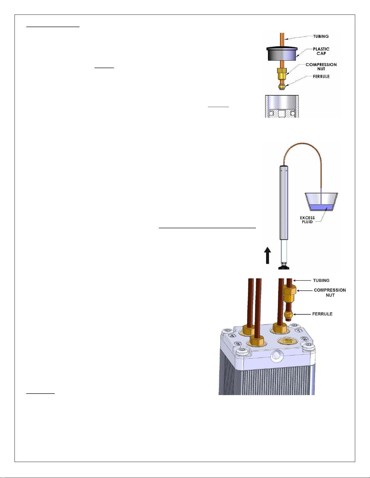
5.0 Tubing Attachment
Original tubing assembly can be reused if undamaged. When cutting a new section of
Movotec® Flexible Hydraulic Tubing to required length, make sure any cuts made are
square and clean. Tubing length must not exceed 196 inches (5m). Slide compression
nut and ferrule onto tubing. NOTE: If a CB cylinder is used, slide plastic cap over tubing
end first as shown below.
To attach tubing to cylinder, insert tubing end into cylinder port. While maintaining a
slight downward pressure on tubing, slide compression nut and ferrule down into port.
Re-tighten compression nut to 84-88 lbf-in (9.5-10 N-m) torque. NOTE: For a CB
cylinder, slide plastic cap down tubing and insert into CB cylinder housing.
For this step, a container will be required to collect fluid. Hold the open end of flexible
tubing over the container. With cylinder in upright position, completely compress
cylinder rod. This action will expel fluid from the cylinder and fill the flexible tubing with
fluid.
CB Cylinder Shown
COMPRESS CYLINDER COMPLETELY
Before reconnecting tubing to pump, make sure that the cylinder is
completely compressed. Slide compression nut and ferrule onto free
end of tubing. Insert free tubing end into pump port. While maintaining
a slight downward pressure on tubing, slide compression nut and
ferrule down into port. Re-tighten compression nut to 84-88 lbf-in (9.510 N-m) torque.
6.0 Operation
Once all cylinders have been refilled and tubing connections are made as needed, re-attach the pump to workstation.
Crank driven systems should now be fully operational and ready for normal use.
For motorized systems, re-attach motorized pump to the workstation. Re-connect the motor cable to the controller. Finally,
connect power cord to a power receptacle. The controller should make an audible “double-clicking” sound. The motorized
system should now be fully operational and ready for normal use.
Rev. 072514 aj Page 5 of 7 ©2013 HAUSMANN INDUSTRIES, INC.
Page 6
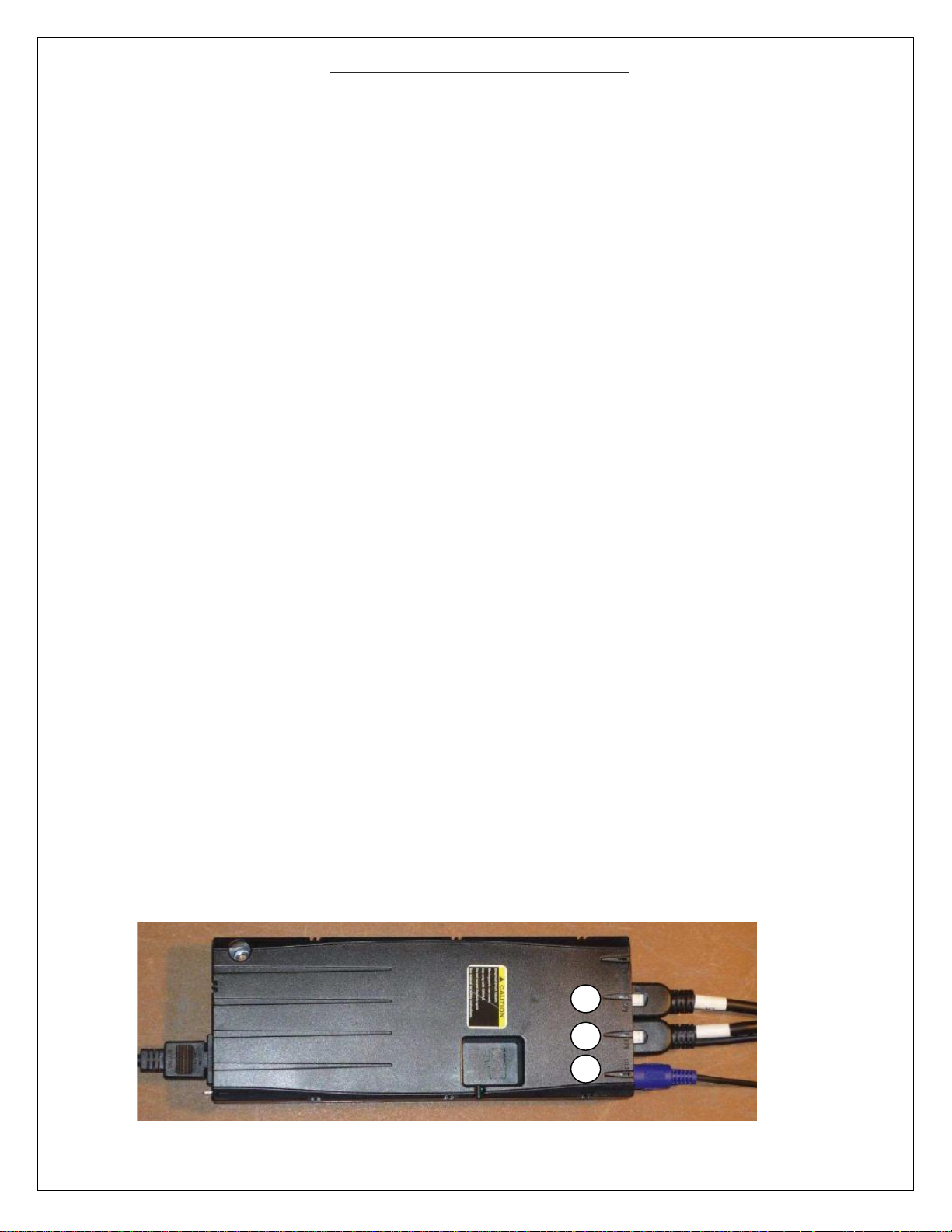
M1
M2
HS
Lift System Controller Reset Procedure
The following procedure should be used to reset a Movotec® Q-Drive motor controller and pump to their respective
“home” positions. The procedure should be performed only if the following conditions exist:
1.) A new or replacement controller is introduced to an existing motor driven system.
The Movotec® Q-Drive motor and motor controller leaves our manufacturing facility programmed as a matched set. If a
different motor controller is used other than the one that was sent with the original unit, it must be matched and
reset with the original motorized pump using the system reset procedure below; the controller will likely force this
procedure when introduced to a new system.
2.) The motor cable is disconnected from the gear motor.
If this happens, reconnect the motor cable to the gear motor. Perform the system reset procedure below to ensure that
the motorized pump will function within its preprogrammed limits.
3.) The system is behaving unusually.
Although it is not very common, a power outage or brown-out condition can cause a motor controller to lose its
programmed position. If this happens, the motor may move in one revolution increments in one or both directions. To
remedy this problem, perform the system reset procedure below.
Remove the motor cables from the “M” slots on the controller (M1, M2, etc.), keeping the switch (the “HS” slot) and
power cord plugged into the control box. After removing the M1 and M2 cables, a reset will be triggered
automatically.
Re-install the M1 and M2 plugs in to their respect ports on the control box.
Press and hold the down button on the switch to bring the system down to its bottom position. Once the system hits
the bottom, release the down button and press and hold it again and the system will automatically move further
down a slight distance and come back up indicating that the system is been reset. Release the down button once the
system is reset.
NOTE: During the reset the system also makes slight single and dual click sound. The double click followed by the
single click indicates that the system is been reset.
After the legs have stopped, remove finger from the down button.
At this point, your lift system should be reset to its home position. To verify, operate the system by moving it upwards with
the up button, and again downwards; ensure the system returns to the home position.
Rev. 072514 aj Page 6 of 7 ©2013 HAUSMANN INDUSTRIES, INC.
Page 7
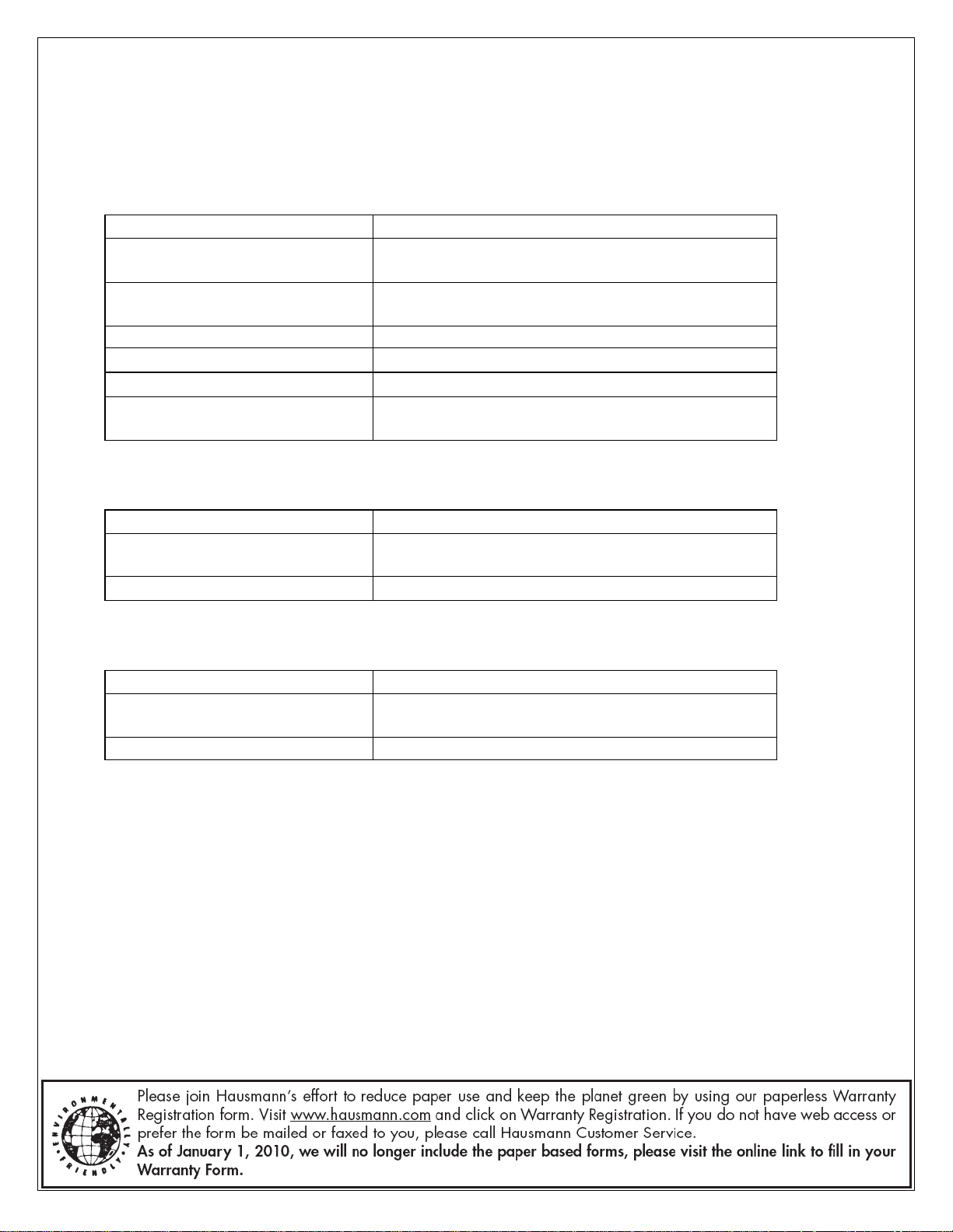
Possible Causes
Recommended Solutions
Power Cord is not connected
Connect power cord to motor controller and/or power
source completely.
Motor Cable is not connected
Connect motor cable to gear motor and/or motor
controller completely.
Switch Cable is not connected
Connect switch cable to motor controller completely.
Defective Motor Controller
Contact Hausmann Industries Inc. for replacement.
Defective Switch
Contact Hausmann Industries Inc. for replacement.
System Load Rating Exceeded
Verify system load does not exceed rating and remove
weight as needed.
Possible Causes
Recommended Solutions
Broken Pusher Block
Contact Hausmann Industries Inc. for replacement
pump.
Broken Coupler Sleeve
Contact Hausmann Industries Inc. for replacement.
Possible Causes
Recommended Solutions
System Load Rating Exceeded
Verify system load does not exceed rating and remove
weight as needed.
Motor Controller in Reset Mode
Perform “System Reset Procedure”
D) TROUBLESHOOTING
Many system problems can be attributed to electrical cables that are not connected correctly, system load conditions,
or incorrect mounting hardware usage. In most cases, problems can be solved by reviewing the following system
problems, possible causes, and implementing the recommended solutions.
Problem: System does not operate.
Problem: Motor runs but does not extend or retract system.
Problem: Motor runs intermittently and requires repeated switch activation.
Rev. 072514 aj Page 7 of 7 ©2013 HAUSMANN INDUSTRIES, INC.
 Loading...