

Page 1
Product Specifications
Model
#
Bar
Length
Height
Width
Weight
Capacity
1340
10’
29”-42”
15" - 28"
400 lbs
1341
7’
29”-42”
15" - 28"
400 lbs
1342
12’
29”-42”
15" - 28"
400 lbs
1343
14’
29”-42”
15" - 28"
400 lbs
1344
16’
29”-42
15" - 28"
400 lbs
1345
18’
29”-42”
15" - 28"
400 lbs
1346
20’
29”-42
15" - 28"
400 lbs
1388
10’
29”-42”
22"-35"
600 lbs
1389
7’
29”-42”
22"-35"
600 lbs
PARTS LIST
Model # 1340, 1341, 1342, 1343, 1344,1345, 1346
Model # 1388, 1389
PART
QUANTITY
DESCRIPTION
PART
QUANTITY
DESCRIPTION
A 4 Adjustable "T" with Control Knobs
A 6 Adjustable "T" with Control Knobs
B 2 Bar (see chart above for length)
B 2 Bar (see chart above for length)
C 4 Upright w/Mounting plate
C 6 Upright w/Mounting plate
D 4 Locking Pin
D 6 Locking Pin
E 4 Adjustable Height Post
E 6 Adjustable Height Post
F 4 Adjustable Arm
F 6 Adjustable Arm
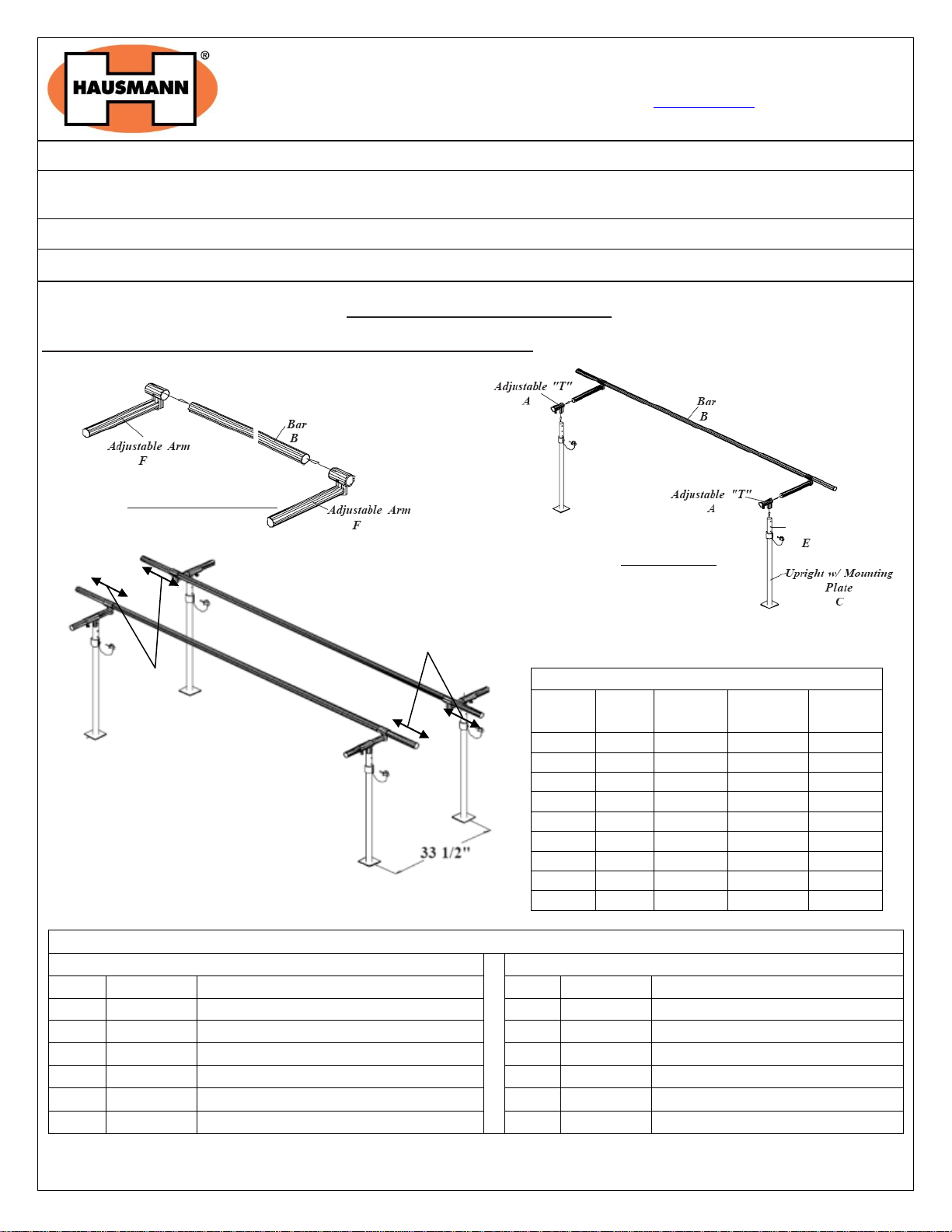
Figure 1: Adjustable Arm & Bar
Figure 2: Bar & Upright
Figure 2: Bar & Upright
Adjustable Height Post
12” to 24”
12” to 24”
HAUSMANN INDUSTRIES, INC.
130 Union St • Northvale NJ 07647 USA • Tel: (201) 767-0255 • Fax: (201) 767-1369 • www.hausmann.com
Installation/Operation Instructions
Parallel Bars - Models S-320, S-321, 1300, 1340, 1341, 1342, 1343, 1344, 1345, 1346, 1384, 1386, 1387, 1388,
1389, 1390, 1391, 1392, 1393
Floor mounted parallel bars such as 1340, 1341, 1342, 1343, 1344, 1345, 1346, 1388, and 1389 on page 1 – 2
Platform mounted parallel bars such as S-320, S-321, 1300, 1384, 1386, 1387, 1390, 1391, 1392, 1393 on page 2 - 4
FLOOR MOUNTED PARALLEL BARS
MODEL # 1340, 1341, 1342, 1343, 1344, 1345, 1346, 1388, 1389
Tools Required:
Allen Wrench (Included)
Rev. 10.09.13 aj Page 1 of 4 ©2013 HAUSMANN INDUSTRIES, INC.
Page 2
Control Knob
Fasteners (not included)
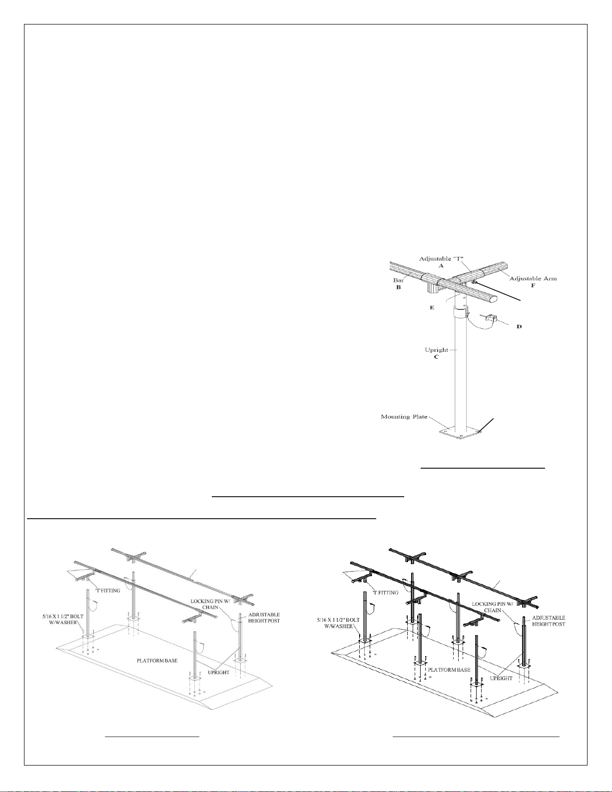
Figure 4: Width & Height Adjustment
Locking Pin
Adjustable Height Post
Bar
Bar
ADJUSTABLE
ARM
ADJUSTABLE
ARM
G H F B C E A
A) INSTALLATION INSTRUCTIONS (1340, 1341, 1342, 1343, 1344, 1345, 1346, 1388, 1389)
To install the parallel bars clear a space big enough to move around with ease.
1. Slide on two (or three for 1388, 1389) Adjustable arms on one bar as shown in Figure 1.
2. Install locking pin in 4
th
hole of Adjustable height post.
3. Once the adjustable arms are in place slide the arms with the bar into the adjustable "T" as shown in Figure 2.
4. When the arms are in the adjustable ‘T’ attach the adjustable ‘T’ to the adjustable height post in the upright as shown
in Figure 2.
5. Repeat steps 1 thru 3 for the other bar.
6. Place outer uprights between 12” to 24” (recommended) from each end of the bar and 33 ½” (recommended) from
center of mounting plate of one bar to center of mounting plate of other in width as shown in Figure 3.
7. After completing steps 1 thru 6 tighten all the set screws to secure the bars in place with the Allen wrench provided.
8. When mounting the uprights attach securely to ground with proper fasteners (not included).
B) OPERATING INSTRUCTIONS (1340, 1341, 1342, 1343, 1344, 1345, 1346, 1388, 1389)
A. To Raise or Lower the bars:
1. Remove the locking pins ‘D’ from one side lift one side to the
desired height, and lock with pin as shown in Figure 4.
2. Raise the other side to the same height and lock.
B. To adjust the width between two bars:
1. Loosen the control knobs on the adjustable "T" by turning
counterclockwise.
2. Move the bars closer or further apart from each other and
tighten the control knob by turning clockwise.
CAUTION:
Before each use, make sure all the control knobs and set screws are in
place and tighten, or injury may occur.
PLATFORM MOUNTED PARALLEL BARS
MODEL # S-320, S-321, 1300, 1384, 1386, 1387, 1390, 1391, 1392, 1393
Figure 5: Bar & Upright (S320) Figure 6: Platform mounted Parallel Bar (1386)
Rev. 10.09.13 aj Page 2 of 4 ©2013 HAUSMANN INDUSTRIES, INC.
Page 3
Product Specifications
Model #
Bar
Length
Height
Width
Weight
Capacity
S320
10’
28”-41”
15" - 28"
350 lbs
S321
7’
28”-41”
15" - 28"
350 lbs
1300
10’
28”-41”
26”
400 lbs
1384
10’
29”-42”
20”-32” (Child)
15" - 28"
400 lbs
1386
10’
29”-42”
22" - 35"
600 lbs
1387
7’
29”-42”
22" - 35"
600 lbs
1390
10’
29”-42”
15" - 28"
400 lbs
1391
7’
29”-42”
15" - 28"
400 lbs
1392
12’
29”-42”
15" - 28"
400 lbs
1393
10’
29”-42”
15" - 28"
400 lbs
PARTS LIST
Model # S320,S321,1300,1384, 1390, 1391,
1392, 1393
Model # 1386,1387
PART
QUANTITY
DESCRIPTION
PART
QUANTITY
DESCRIPTION
A 4 Adjustable "T"
A 6 Adjustable "T"
B
2
4
Bar (see chart above for length)
Bar (Only for 1384)
B 2 Bar (see chart above for length)
C 4 Upright C 6
Upright
D 4 Locking Pin
D 6 Locking Pin
E 4 Adjustable Height Post
E 6 Adjustable Height Post
F 4 Adjustable Arm (N/A for 1300)
F 6 Adjustable Arm
G 1 Platform Base
G 1
Platform Base
H
16
5/16” x 1 ½” Bolt W/ Lock Washer
H 24
5/16” x 1 ½” Bolt W/ Lock Washer
I 4 Control Knobs (N/A for 1300)
I 6
Control Knobs
J
11
Ladder Steps (1393 only)
K 1 Balance Beam 89 ¾”L x 6”W x 3
3/8”H (1393 only)
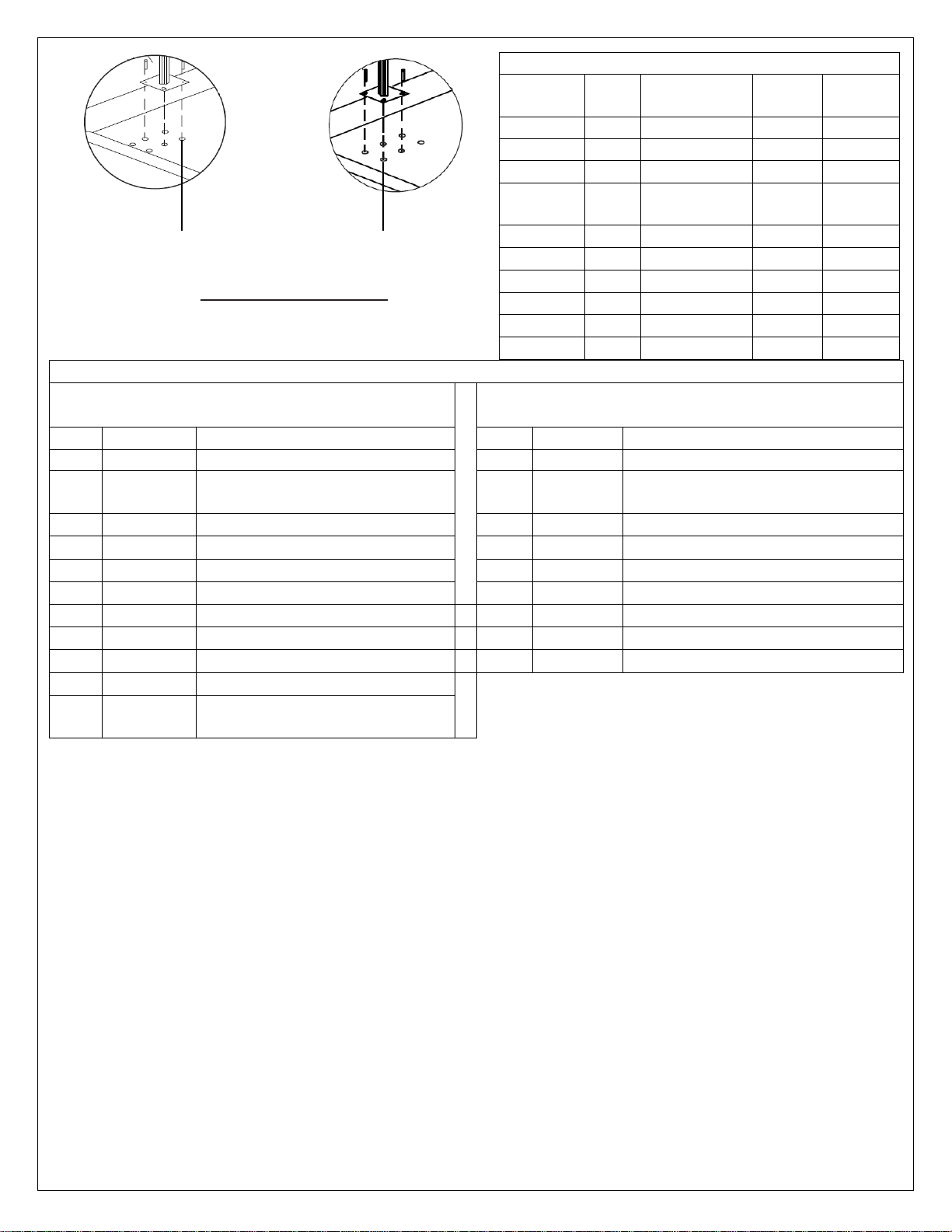
Innermost 4 holes for
Model #1300
Outermost 4 holes for Model #
S320, S321, 1300, 1384, 1386,
1387, 1390, 1391, 1392, 1393
Figure 7: Inner and Outermost holes
Tools Required:
Allen Wrench (Included)
A) INSTALLATION INSTRUCTIONS (S320, S321, 1300, 1386, 1387, 1390, 1391, 1392 & 1393)
To install the parallel bars clear a space big enough to move around with ease.
1. Place Uprights on Platform Base as shown in Figure 6.
2. Secure Uprights to Platform Base using 5/16” x 1 ½” Bolts and Lock Washers (included).
NOTE: Use innermost four holes to mount for Model # 1300 and outermost four holes for Model # S320, S321, 1390,
1391, 1392 and 1393 as shown in Figure 7.
3. Install locking pin in 4
4. Only for Model #1300 , Slide the two ‘T’ fittings on each bar and then place them onto the Adjustable height post in the
uprights and go to step 9.
5. Slide on two (or three for Models 1386 & 1387 only) Adjustable arms on one bar as shown in Figure 1 page 1.
6. Once the adjustable arms are in place slide the arms with the bar into the adjustable ‘T’ as shown in Figure 5.
7. When the arms are in the adjustable ‘T’ attach the adjustable ‘T’ to the adjustable height post in the upright as shown
in Figure 5.
8. Repeat steps 1 thru 3 for the other bar.
9. After completing all steps, tighten all the set screws to secure the bars in place with the Allen wrench provided.
Rev. 10.09.13 aj Page 3 of 4 ©2013 HAUSMANN INDUSTRIES, INC.
th
hole of Adjustable height post.
Page 4
Plan ‘A’ Plan ‘B’
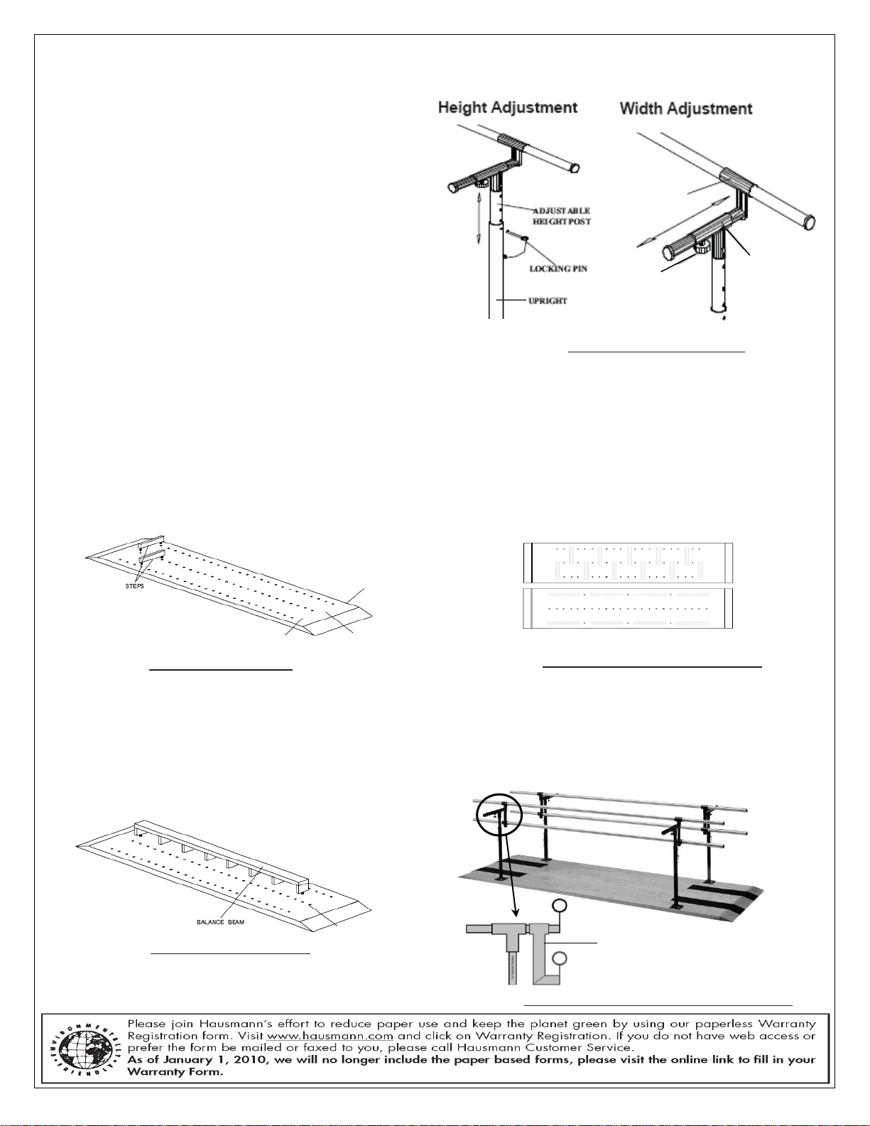
Figure 8: Height & Width Adjustment
CONTROL KNOB
WIDTH
ADJUSTABLE
ARM
‘T’ FITTING
I
Figure 9: Step ladder placement
Figure 11: Balance beam placement
J K B
A
B
C
Figure 10: Ladder placed with Plan ‘A’ and ‘B’
Pediatric Add-On Fitting
Figure 12: 1384 Combination Adult/Child Parallel Bar
B) OPERATING INSTRUCTIONS (S320, S321, 1300, 1386, 1387, 1390, 1391, 1392 & 1393)
A. To Raise or Lower the bars:
1. Remove the locking pin from upright
2. Raise or lower the Adjustable height post to the
desired height, and insert the locking pin back
into upright to lock as shown in Figure 8.
3. Repeat steps 1 and 2 above to set the height for
other adjustable height posts.
B. To adjust the width between two bars: (N/A for
Model # 1300)
1. Loosen the control knobs on the adjustable "T"
by turning counterclockwise.
2. Move the adjustable arm in or out to the
desired position and tighten the control knob by
turning clockwise.
CAUTION:
Before each use, make sure all the control knobs and set screws are in place and tighten, or injury may occur.
Step Ladder and Balance Beam Placement Instructions (Model # 1393 only)
A. The Placement of Ladder Steps:
Alternate the steps by inserting into one holes “B” and “C”, then the second in “A” and “B”. Continuing as
required as shown in Figure 9 and 10.
B. The Placement of Balance Beam:
Insert the beam into the second to last holes in line ‘B’ from each end of the platform as shown in Figure 11.
NOTE: It is not necessary to remove the ladder steps prior to installing the balance beam. Balance beam is
designed to fit over previously installed steps.
Rev. 10.09.13 aj Page 4 of 4 ©2013 HAUSMANN INDUSTRIES, INC.
 Loading...