

haupa AS-6 Instruction Manual

...convincing solutions
Q
ZERTIFIKAT
DIN EN ISO 9001
INSTRUCTION MANUAL
BATTERY POWERED HYDRAULIC PUNCHER
„AS-6“
Art.
21 67 00

2
1. CARACTERISTICAS TECNICAS
Maximum cutting capacity: Ø 118 mm, 2.5 mm thick steel plate 92 x 92 mm, 2 mm thick steel plate
Endurance: 180 holes in Ø 22.5 mm (PG16)
Punch time: 6 sec
Max yield strength: 45 Kg/mm
2
Cutting force: 60 KN
Operating pressure: 650 bar
Flow rate at 700 bar: 0,16 l/emb
Reservoir capacity: 0,32 L
Voltage: 12 V
Battery: 2 Ah
Charge time: Approx 50 min (at 20ºC)
Dimensions: 280 x 230 mm
Weight + battery: 3,3 Kg
Box: 415 x 315 x 95 mm
Tool composition: - 1 PHB-110
- 1 M20 drive shaft (cod.; 1470200)
- 1 M20 / 10 Reducer (Cod. 1470100)
- 2 M10 drive shafts (cod: 1450100)
- 1 spacer (cod: 1470300)
- 2 Batteries
- 1 battery charger
- 1 carrying strap
- 1 metal transport box
2. OPERATING RANGE
2.1. 2.5 mm thick sheet metal, 370 N/mm
2
yield strength
2.1.1. Standard dimensions PG TYPE:
PG-9 Ø 15,2 mm PG-29 Ø 37 mm
PG-11 Ø 18,6 mm PG-36 Ø 47 mm
PG-13 Ø 20,4 mm PG-42 Ø 54 mm
PG-16 Ø 22,5 mm PG-48 Ø 60 mm
PG-21 Ø 28,3 mm B.CETACIII Ø 65 mm
PILOT Ø 30,5 mm
2.1.2. Standard dimensions METRIC TYPE:
M-16 Ø 16,5 mm M-40 Ø 40,5 mm
M-20 Ø 20,5 mm M-50 Ø 50,5 mm
M-25 Ø 25,5 mm M-63 Ø 63,5 mm
M-32 Ø 32,5 mm
2.2. Customised dimensions from a minimum diameter of Ø 15 mm to a maximum of Ø 118 mm
2.3. 2 mm thick sheet metal, 370 N/mm
2
yield strength
2.3.1. Standard SQUARE dimensions (FOR AMMETERS):
AMP.48 46 x 46 mm
AMP.72 68 x 68 mm
AMP.96 92 x 92 mm
2.4. Standard RECTANGULAR dimensions (FOR DIFFERENTIALS):
DIFFERENTIAL 47 x 71 mm
2.5. Customised dimensions from a minimum of 18 x 18 mm to a maximum of 92 x 92 mm after prior consultation.

Stud
Die
Punch
Shim
Germany: HAUPA, Königstr. 165-169, 42853 Remscheid
Phone: +49 (0)2191 8418-0, Fax: +49 (0)2191 8418-840, sales@haupa.com • Errors and technical changes reserved.
…convincing solutions
english
3
3. OPERATING INSTRUCTIONS
3.1. OPERATION
• This lightweight user-friendly Battery powered Hydraulic Puncher is the best option for both on-site and
factory shop work.
• This tool is a must for all skilled workers specialising in the assembly of aluminium, steel plate or plastic
switching panels, regardless of whether the surface is painted or not.
3.2. TO OPERATE
3.2.1. Prior drilling. Use a drill to make an initial Ø 11 mm hole in the plate to be punched.
3.2.2. Mount the draw studs and spacers
• Mount the M20/10 (pos 39) reducing stud on the tool, screwing it right down to the bottom.
• Locate the spacers (pos 5) on the stud and then mount the die.
• Insert the projecting part of the M10 stud into the hole drilled in the plate.
• Screw the punch into the M10 stud until it comes to a stop against the plate to be punched.
3.2.3. Punching operation
• Press the operating button and perform the punching operation until you observe that the plate
– swarf has been knocked out.
• Then perform the operations in the reverse order. In other words, press the discharge trigger
(pos 30), unscrew the punch from the stud. The cut piece will easily come out of the die.
3.2.4. Making holes greater than Ø 31 mm
• Perform the above-mentioned operations until a hole of Ø 20.4 mm minimum has been made.
• Unscrew the M10 stud and the M20/10 reducer
• Screw in the M20 (pos 38) stud until it comes to a stop.
• Insert the spacer on the shaft
• Mount the die on the spacer and insert the rest of the shaft through the Ø 20.4 mm hole.
• Screw the punch onto the M20 stud until it comes to a stop against the sheet metal and then
proceed to punch, as indicated in the points above.
3.2.5. Making square or rectangular holes
• To make these holes, proceed as for the previous point (point 3.2.4).
drill bit
4
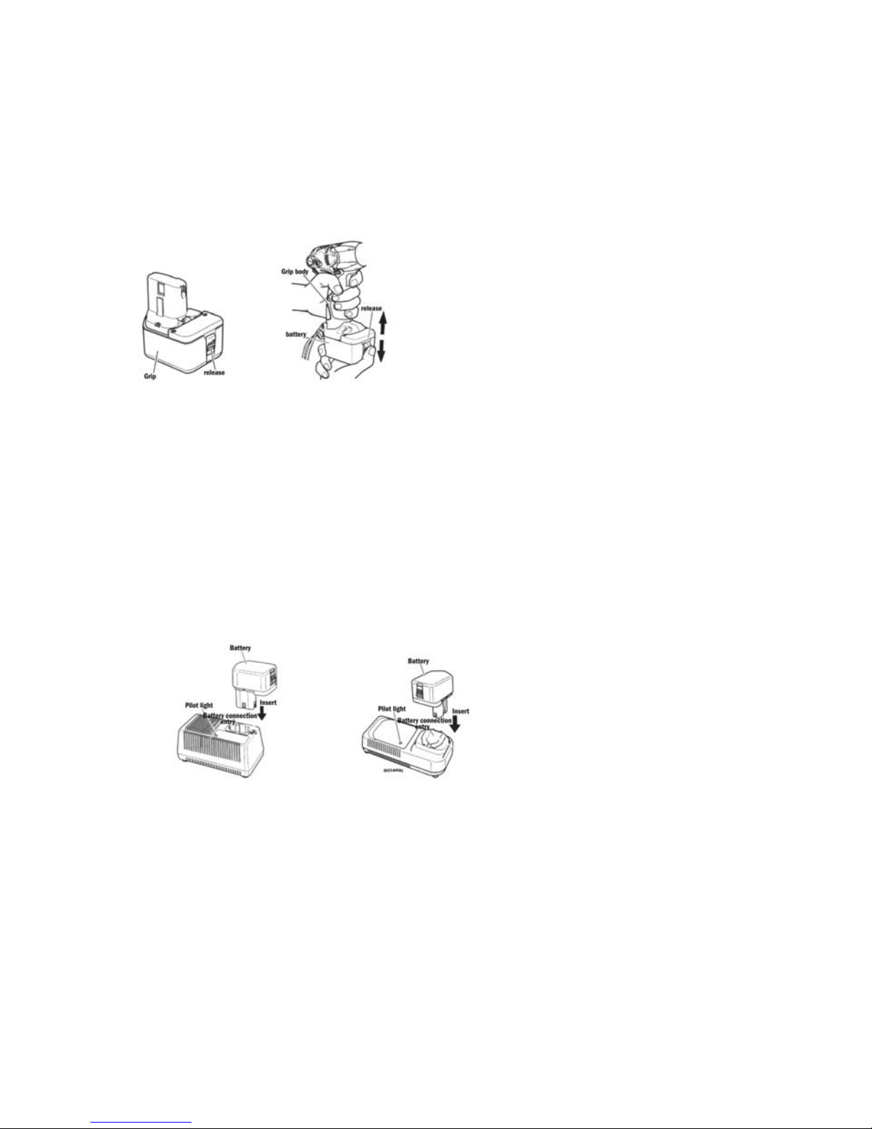
4. BATTERY REMOVAL AND INSTALLATION
4.1. Battery removal.
Hold the grip firmly and press the battery release button to remove it, as shown in the following figures.
CAUTION
Never short circuit the battery
1. Battery installation
Insert the battery ensuring that the poles are correct (see previous figures)
4.2. Battery charging.
Before using the tools, charge the battery as follows:
4.2.1. Plug the charger cable into an AC socket.
Once the charger plug has been connected to the mains, the red pilot light will light (At 1 second intervals).
4.2.2. Insert the battery in the charger.
Firmly insert the battery, in the direction indicated in the following figures, until it comes into contact with the
charger compartment bottom.
CAUTION
If the battery is inserted the wrong way round, apart from not charging this could also damage the charger, such as the deformation of the charging terminal.
4.3. Battery charging.
When you insert a battery into the charger, the battery will start to charge and the red pilot light will be on continuously.
Once the battery is completely charged, the red pilot light will flash (at one second intervals). See the following table:
4.3.1. Pilot lamp indications.
The following table shows the different pilot light indications according to the charger or battery status.
 Loading...