

haupa 21 66 01 Instruction Manual

Q
ZERTIFIKAT
DIN EN ISO 9001
… convincing solutions
Electro hydraulic crimping tool
Art. 21 66 01
INSTRUCTION MANUALHydraulic pliers

1. Technical characteristics
Application field: A compression tool for crimping electrical connectors,
suitable for copper conductors up to 400 mm2and aluminium
conductors up to 300 mm
2
.
Force developed: 120 kN
Press opening: 25 mm
Rated operating pressure: 700 bar
Oil type: ISO class viscosity 15
Voltage 14.4V
Battery: 3.0 Ah
Speed of advance: The tool moves at two speeds. A speed to move the dies
together and a slower speed for the crimping action.
The changeover from one speed to the other is automatic.
Safety: The tool is equipped with a factory-set safety valve.
Sicherheitsventil ausgestattet.
Construction: 216601 model features a built-in drive pump.
It is equipped with an 180º rotating head for easy access in
confined areas. The model 216601 is not designed to protect the
operator in hot line work.
2. Working range
Pressure: 120 kN
Crimping range: DIN cable lugs 300 mm
2
standard copper 400 mm
2
aluminium 240 mm
2
Crimping time: 6 - 12 sec.
Charging time for batteries: 20 min
Battery voltage: 14.4 V
Battery capacity: 3.0 Ah
Working pressure: 700 bar
Dimension: 335 x 310 x 75 mm
Weight: 7 kg
Weight Set: 12 kg
Germany: HAUPA GmbH & Co. KG, Königstraße 165-169, D- 42853 Remscheid.
Phone: +49 (0)2191 8418-0, Fax: +49 (0)2191 8418-840, sales@haupa.com • Errors and technical changes reserved.
… convincing solutions
english
3. Instrucctions for use
WARNING! NEVER USE THE TOOL WITHOUT FIRST INSERTING THE DIE SET.
Ensure that the dies correspond exactly to the area to be crimped and that the dies are perfectly
positioned in their corresponding holders.
FAILURE TO DO SO COULD RESULT IN SERIOUS DAMAGE OR BREAKAGES AND WOULD VOID
THE GUARANTEE.
Preparation:
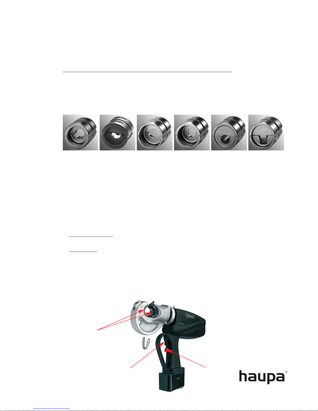
• Select the correct die for the connection to be made.
• Insert the die set in the tool head. All the dies used in these models are semicircular,
regardless of the type of compression or crimping to be performed. Both die parts have
identical outside dimensions and can therefore be mounted indistinctly on either the piston
or the head. The same procedure is used for mounting the dies on both the piston and the
head.
• Insert the die along the guides, until it comes to a stop against the locking pin.
• Then, remove the locking pin by pressing the release button and continue to insert the die
until it is retained in position by the pin.
• For t
he piston side: To carry out the above-mentioned operations, it is first necessary to
move the piston forward to allow access to the release button.
• Die remo
val: The procedure is also the same for both parts of the die set. Release by pres
sing the locking buttons and slide the die outwards. When removing the die from the
piston, reverse the procedure described in the previous point.
Die holder
Pushbutton
to advance
Pushbutton for
return movement
 Loading...