

Haulotte Quick Up 7, Quick Up 9, Quick Up 11, Quick Up 12, Quick Up 13 Operation And Maintenance Instructions
...
OPERATION AND
MAINTENANCE INSTRUCTIONS
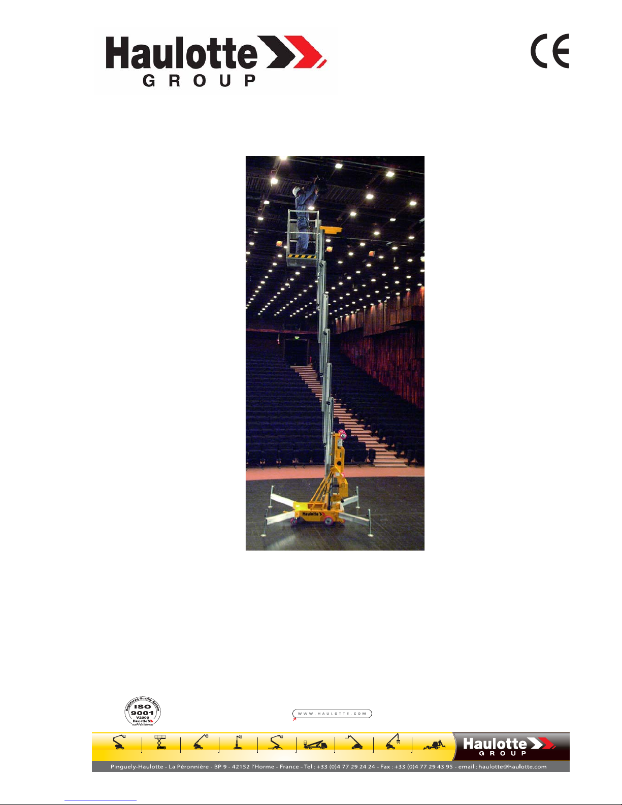
PUSH AROUND
Quick Up 7 - 8 - 9 - 11 - 12 - 13 - 14
242 032 9580 - E 07.08 GB


Distribué par / Distributed by/ Distribuito da
Haulotte France
Tél / Phone +33 (0)4 72 88 05 70
Fax / Fax +33 (0)4 72 88 01 43
Centre Mondial Pièces de Rechange
Spare Parts International Centre
Tél / Phone +33 (0)4 77 29 24 51
Fax / Fax +33 (0)4 77 29 98 88
Haulotte Hubarbeitsbühnen
Tél / Phone + 49 76 33 806 920
Fax / Fax + 49 76 33 806 82 18
Haulotte Portugal
Tél / Phone + 351 21 955 98 10
Fax / Fax + 351 21 995 98 19
Haulotte UK
Tél / Phone + 44 (0) 1952 292753
Fax / Fax + 44 (0) 1952 292758
Haulotte U.S. Inc.
Main tool free 1-877-HAULOTTE
Service tool free 1-877-HAULOT-S
Haulotte Singapore Pte Ltd
Tél / Phone + 65 6536 3989
Fax / Fax + 65 6536 3969
Haulotte Netherlands BV
Tél / Phone + 31 162 670 707
Fax / Fax + 31 162 670 710
Haulotte Australia PTY Ltd
Tél / Phone + 61 3 9706 6787
Fax / Fax + 61 3 9706 6797
Haulotte Italia
Tél / Phone + 39 05 17 80 813
Fax / Fax + 39 05 16 05 33 28
Haulotte Do Brazil
Tél / Phone + 55 11 3026 9177
Fax / Fax + 55 3026 9178
Haulotte Scandinavia AB u.b.
Tél / Phone + 46 31 744 32 90
Fax / Fax + 46 31 744 32 99
Haulotte Iberica - Madrid
Tél / Phone + 34 91 656 97 77
Fax / Fax + 34 91 656 97 81
Haulotte Iberica - Sevilla
Tél / Phone + 34 95 493 44 75
Fax / Fax + 34 95 463 69 44


Why use only Haulotte original spare-parts ?
1. RECALLING THE EEC DECLARATION OF CONFORMITY IN QUESTION
Components, substitutions, or modifica tions other than t he ones recommended by
Haulotte may recall in question the initia l security conditions of our Haulotte equipment.
The person who would have intervened for any operation of this kind will take responsibility
and recall in question the EEC ma rking validity granted by Haulotte. The EEC declaration
will become null and void and Haulotte will disclaim regulation responsibility.
2. END OF THE WARRANTY
The contractual warranty of fered by Haulotte for it s equipment will no longer be app lied
after spare-parts other than original ones are used.
3. PUBLIC AND PENAL LIABILITY
The manufacture and unfair competition of fake spare-parts will be sentenced by public and
penal law. The usage of fake sp are-parts w ill invoke the civil and penal liability of the
manufacturer, of the ret ailer, and, in some cases, of the per son who used the fake sp areparts.
Unfair competition invokes the civil liability of the manufacturer and the retailer of a “slavish
copy” which, t aking unjustifi ed adva ntage of this operation, distorts the normal rules of
competition and creates a “p arasitism” act by divertin g ef forts of design, perfection,
research of best suitability, and the know-how of Haulotte.
FOR YOUR SECURITY, REQUIRE HAULOTTE ORIGINAL SPARE-PARTS

4. QUALITY
Using Haulotte original spare-parts means guarantee of :
• High quality partsl
• The latest technological evolution
• Perfect security
• Peak performance
• The best service life of your Haulotte equipment
• The Haulotte warranty
• Haulotte technicians’ and repair agents’ technical support
5. AVAILABILITY
Using Haulotte original sp are-parts allows you to t ake advant age of 40 000 references
available in our permanent stock and a 98% service rate.
WHY NOT TAKE ADVANTAGE ?

Operation and maintenance
i
Caution!
GENERAL
You have just received your Quick Up machine.
This machine will give you total satisfaction if you follow these operation
and maintenance instructions carefully.
This manual is intended to help you.
We insist on the importance of:
• compliance with the safety instructions concerning the machine itself, its use
and its environment,
• use within the limits of the machine,
• correct maintenance, which will affect the machine’s lifetime.
During and after the warra nty period, ou r Aftersales de partment is
available to provide any services you may require.
When contacting your local agent or our aftersales department, specify
the exact machine type and its serial number.
When ordering consumab les or spar e p arts, use this ma nual and the
"Spare parts" catalogue to ensure use of original parts, which is the sole
guarantee of interchangability and proper operation.
This instruction manual is supplied with the machine and is mentioned on
the delivery note.
REMINDER:Quick Up machines conform to the clauses of the Machines Directi-
ve, 89/392/CEE dated June 14 1989, amended by directives 91/368/
CEE d ated Ju ne 21 1 991, 93/44 /CEE da ted Jun e 1 4 19 93, 9 3/68/
CEE (98/37/CE) dated July 22 1993 and 89/336 CEE dated May 3
1989; as well as to directive 2000/14/CE and directive EMC/89/336/
CE.
THE TECHNICAL DATA GIVEN IN
THIS MANUAL IS NOT BINDING.
W
E RESERVE THE RIGHT TO
MAKE IMPROVEMENTS OR
ALTERATIONS WITHOUT
MODIFYING THIS MANUAL.

Operation and maintenance
ii

Operation and maintenance
iii
CONTENTS
1 - GENERAL RECOMMENDATIONS - SAFETY ............................................................ 1
1.1 - GENERAL WARNING ................................................................................................. 1
1.1.1 - Manual ..................................................................................................................................... 1
1.1.2 - Labels ...................................................................................................................................... 1
1.1.3 - Safety....................................................................................................................................... 1
1.2 - GENERAL SAFETY INSTRUCTIONS......................................................................... 2
1.2.1 - Operators................................................................................................................................. 2
1.2.2 - Environment............................................................................................................................. 2
1.2.3 - Using the machine ................................................................................................................... 2
1.3 - RESIDUAL RISKS ....................................................................................................... 4
1.3.1 - Risks of trembling or overturning ............................................................................................. 4
1.3.2 - Electric risks............................................................................................................................. 4
1.3.3 - Risks of explosion or burning................................................................................................... 4
1.3.4 - Risks of collision ...................................................................................................................... 4
1.4 - VERIFICATIONS ......................................................................................................... 4
1.4.1 - Periodic checks........................................................................................................................ 4
1.4.2 - Examination of machine suitability........................................................................................... 5
1.4.3 - State of repair .......................................................................................................................... 5
1.5 - REPAIRS AND ADJUSTMENTS................................................................................. 5
1.6 - VERIFICATIONS BEFORE RESUMING OPERATION............................................... 5
1.7 - BEAUFORT SCALE ................................................................................................... 5
1.8 - MINIMUM SAFETY DISTANCES ................................................................................ 6
2 - PRESENTATION ......................................................................................................... 7
2.1 - IDENTIFICATION ........................................................................................................ 7
2.2 - MAIN COMPONENTS ................................................................................................. 8
2.3 - TECHNICAL CHARACTERISTICS ............................................................................. 9
2.3.1 - Quick Up technical characteristics........................................................................................... 9

Operation and maintenance
iv
2.4 - SIZE .............................................................................................................................9
2.4.1 - Size .......................................................................................................................................... 9
2.5 - LABELS......................................................................................................................10
2.5.1 - List of labels ........................................................................................................................... 10
2.5.2 - Common "red" labels ............................................................................................................. 11
2.5.3 - Common "yellow" labels......................................................................................................... 12
2.5.4 - Common "orange" labels ....................................................................................................... 12
2.5.5 - Miscellaneous common labels .............................................................................................. 12
2.5.6 - Specific "red" labels................................................................................................................ 13
2.5.7 - Positionning labels ................................................................................................................. 13
3 - OPERATING PRINCIPLE...........................................................................................15
3.1 - HYDRAULIC CIRCUIT...............................................................................................15
3.2 - ELECTRIC CIRCUIT..................................................................................................15
3.2.1 - Stabiliser control..................................................................................................................... 15
4 - USE.............................................................................................................................17
4.1 - UNLOADING - LOADING - MOVING.........................................................................17
4.1.1 - Manual loading....................................................................................................................... 17
4.1.2 - Manual unloading................................................................................................................... 18
4.1.3 - Unloading with a lift truck ....................................................................................................... 19
4.1.4 - Unloading by lifting ................................................................................................................. 19
4.1.5 - Moving.................................................................................................................................... 19
4.2 - OPERATIONS BEFORE FIRST USE ........................................................................21
4.2.1 - "Mast" control panel ............................................................................................................... 21
4.2.2 - "Platform" control panel.......................................................................................................... 22
4.2.3 - Checks before use ................................................................................................................. 22
4.3 - STARTING UP ...........................................................................................................23
4.3.1 - Power on................................................................................................................................ 23
4.3.2 - Machine stabilisation.............................................................................................................. 23
4.3.3 - Up/Down................................................................................................................................. 23
4.3.4 - Testing the platform control panel.......................................................................................... 24
4.3.5 - Stopping the machine............................................................................................................. 24

Operation and maintenance
v
4.4 - EMERGENCY AND RESCUE OPERATIONS .......................................................... 24
4.4.1 - Emergency lowering .............................................................................................................. 24
4.4.2 - Rescue lowering .................................................................................................................... 24
4.5 - USE AND MAINTENANCE OF BATTERIES............................................................. 25
4.5.1 - Starting operation................................................................................................................... 25
4.5.2 - Discharge............................................................................................................................... 25
4.5.3 - Charge ................................................................................................................................... 25
4.5.4 - Servicing ................................................................................................................................ 25
5 - MAINTENANCE ......................................................................................................... 27
5.1 - GENERAL RECOMMENDATIONS ........................................................................... 27
5.1.1 - Periodical servicing................................................................................................................ 28
5.1.2 - Operating instructions............................................................................................................ 29
6 - OPERATING INCIDENTS.......................................................................................... 33
7 - HYDRAULIC DIAGRAM ............................................................................................ 35
7.1 - AC VERSION............................................................................................................. 35
7.2 - DC VERSION ............................................................................................................ 36
8 - WIRING DIAGRAMS.................................................................................................. 37
8.1 - AC VERSION............................................................................................................. 37
8.2 - DC VERSION ............................................................................................................ 38
9 - REGISTER OF INSPECTION AND REPAIR............................................................. 39

Operation and maintenance
vi
Operation and maintenance
1
Caution!
1 - GENERAL RECOMMENDATIONS - SAFETY
1.1 - GENERAL WARNING
1.1.1 - Manual
This manual aims to help the operator to get to know the Quick Up machine
to provide for efficient and SAFE use. However, this manual cannot be a
substitute for the basic training required by any site equipment operator.
The comp any ma nager is r equired to infor m ope rators of th e
recommendations in th e instru ction man ual. He is also r esponsible for
applying any "user regulations" in force in the country of use.
Before using the machine, it is essential to be familiar with and undertsand
all these instructions to ensure safe and efficient use of the equipment.
This instruction manual must be available to all operators. Extra copies can
be supplied on request.
1.1.2 - Labels
Potential h azards an d ma chine instru ctions ar e in dicated by lab els an d
plates. Read the instructions on these labels and plates.
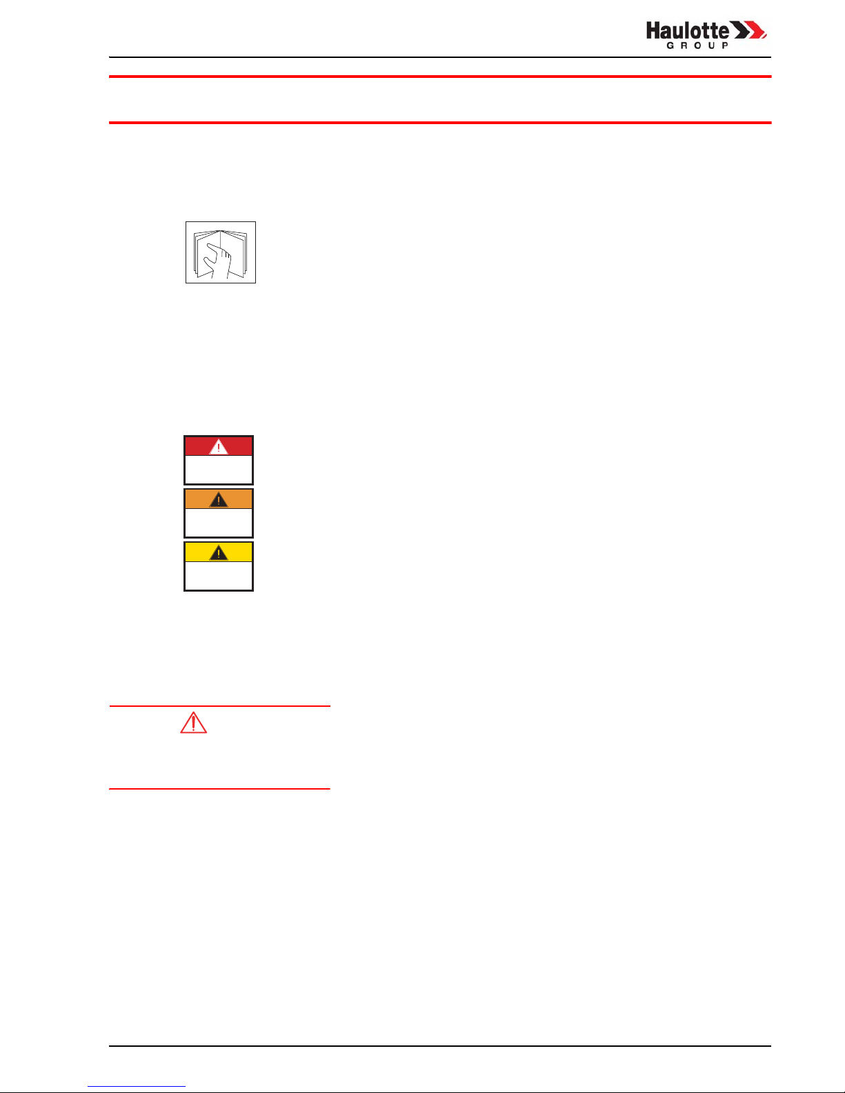
All labels use the following colour code:
• Red indicates a potentially fatal hazard.
• Orange indicates a hazard that may cause serious injury.
• Yellow indicates a hazard that may cause material damage or slight
injury.
The company manager must ensure that all labels and plates are in good
condition and legible. Extra copies can be supplied by the manufacturer on
request.
1.1.3 - Safety
Ensure that any person entrusted with the machine is able to comply with
the safety measures required by its use.
Avoid any work cond itions liab le to affect safety. Any use that do es not
conform to th e instru ctions m ay incur risks an d da mage to pe ople an d
materials.
To attract the reader’s attention,
instructions are indicated by this
standard symbol.
Ensure that all plates and labels related to safety and hazards are complete
and legible.
Operation and maintenance
2
Caution!
1.2 - GENERAL SAFETY INSTRUCTIONS
1.2.1 - Operators
Operators must be aged over 18 and hold an operating permit issued by
the employer after verification of physical aptitude and practical platform
operation tests.
Only trained operators may use
Haulotte self-propelled platforms.
There must be at least two operators so that one can:
• react quickly in an emergency,
• take over the controls in the event of accident or failure,
• monitor a nd p revent ve hicles and ped estrians from mo ving ar ound
the platform,
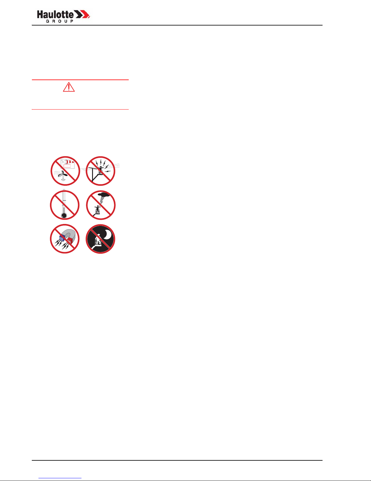
1.2.2 - Environment
This machine is for indoor use only.
Never use the machine:
• on soft, unstable or cluttered ground,
• on a slope that is greater than the permitted slope,
• with a windspeed high er than the pe rmitted limit. If th e machin e is
used ou tside, use a n a nemometer to check that wind speed is less
than or equal to the permitted limit.
• near electric lines (find out minimum distances according to voltage),
• in temperatures of less than -29°C (particularly in cold rooms), consult
us if work is to be carried out at less than -29°C.
• in an explosive atmosphere,
• during storms (lightning risk),
• in the dark without floodlighting,
• in the presence of intense electromagnetic fields (radar, or high currents).
1.2.3 - Using the machine
It is important to ensure that in normal operation, i.e. platform operation, the
platform/turntable station selection key must be removed and kept on the
ground by a person present and trained in emergency/rescue manoeuvres.
Do not use the machine with:
• load greater than the allowed load,
• more people than the authorised number,
• a lateral force in the platform greater than the permissible limit (See
Chap 2.3, page 9).
X km/h
Y km/h
Y>X
-29
0
°C
Operation and maintenance
3
Caution!
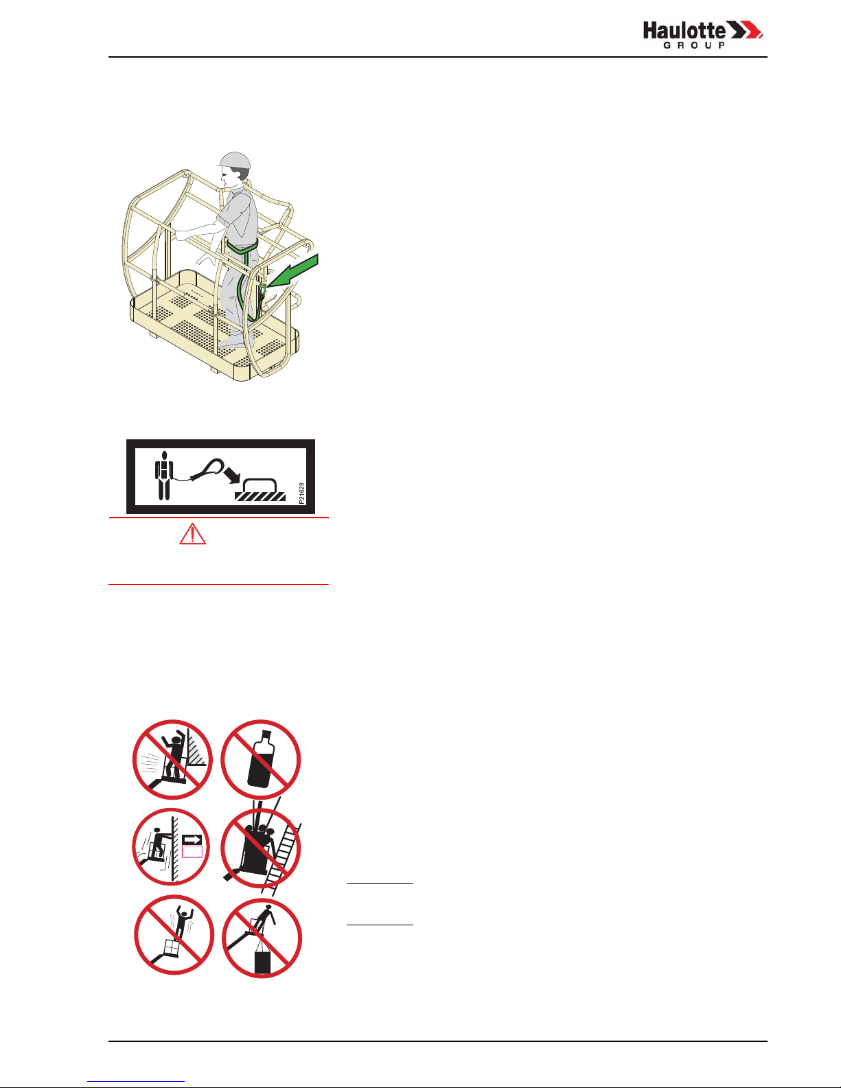
To reduce the risk of falls, op erators must comply with the following
instructions:
• firmly hold the barrier when the machine is moving,
• wipe all traces of oil or grease from the steps, floor or hand rails,
• wear personal protective gear suited to the work conditions and applicable lo cal re gulations, in p articular whe n wor king in ha zardous
areas,
• do not disable the safety end of travel sensors,
• avoid hitting stationary or moving obstacles,
• do not use ladders or other accessories to increase working height,
• do not use the barrier as a means of access to climb into or out of the
platform (use the steps provided on the machine),
• do not climb on the barrier while the machine is raised,
• do not use the machine without setting up the platform’s protective bar
or closing the safety gate,
• do not climb on the covers.
All Quick Up mach ines a re e quipped wit h app roved an chor point s
that will ac cept a single harness per point of anchor. These a nchor
points are indicated by the label opposite.
If local and government regulations in force in the country of use impose the wearing of a harness, we recommend use of these approved
anchor points.
Do not use the machine as a crane,
goods lift or elevator.
To avoid risks of ove rturning, ope rators must comply with th e
following instructions:
• stabilisers must always be engaged wh ilst the platform is raised and
must not be released until the platform is in the fully stowed position,
• do not disable safety end of travel contactors,
• respect the maximum load, and the number of people authorised in
the platform,
• spread the load and place in the centre of the platform if possible,
• check that the ground resists the pressure and load per wheel,
• avoid hitting stationary or moving obstacles,
• do not use the machine with a cluttered platform,
• do not use the machine with equipment or objects hanging from the
guardrails,
• do not use the machine with elements that may increase its wind resistance (e.g.: panels),
• do not perform machine maintenance operations while the machine is
raised without implementing the necessary safety precautions (gantry
crane, crane),
• perform daily checks and monitor correct operation during periods of
use.
NOTE: Do not tow the Quick Up (it is not designed to be towed and
must be transported on a trailer).
200 N
(20 kg)
Operation and maintenance
4
Caution!
1.3 - RESIDUAL RISKS
1.3.1 - Risks of trembling or overturning
The risks of trembling or overturning are high in the following situations:
- sudden action on the control levers,
- platform overload,
- ground collapse (be careful during thaw periods in winter),
- gusts of wind,
- hitting an obstacle on the ground or overhead,
- working on raised pavements, etc.
1.3.2 - Electric risks
If the machine has a 220 V, 16A max.
socket, the extension must be
connected to a mains socket,
protected by a 30mA differential
circuit breaker.
Electric risks are high in the following situations:
- contact with a live line,
- use during storms.
See “Minimum safety distances”, page 6
1.3.3 - Risks of explosion or burning
The risks of explosion or burning are high in the following situations:
- work in an explosive or inflammable atmosphere,
- use of a machine with a hydraulic leak.
1.3.4 - Risks of collision
- Risk o f crushing people lo cated within the m achine’s op erating
area.
- The operator must evaluate any overhead risks before using the
machine.
1.4 - VERIFICATIONS
Comply with current legislation in the country of use.
In FRANCE: Order dated March 1st 2004 + DRT 2005-04 instruction dated
march 24th 2005 specifying:
1.4.1 - Periodic checks
The machine must be examined every 6 months to detect any defects that
may cause an accident.
These examinations are carried out by an external organisation or a person
specially appointed by the company manager and reporting directly to him
(employee of the company or otherwise) Articles R 233-5 and R 233-11 of
the Labour Code.
The results of these examinations are recorded in a safety log kept by the
company ma nager, available at all times to the fa ctory inspector and the
company’s hea lth an d safety com mittee, if the re is on e. The list of an y
specially appointed persons is also to be available similarly (Article R 2335 of the Labour Code).
NOTE: This log can be obtained from professional organisations and
from the OPPBTP or private prevention organisations.
The appointed persons must be experienced in the field of risk prevention
(Articles R 233-11 of decree no. 93-41).
No-one may perform any verifications during machine operation (Article R
233-11 of the Labour Code).

Operation and maintenance
5
1.4.2 - Examination of machine suitability
The manager of the company in which this machine is used must ensure
that the machine is suitable, i.e. suitable to the work to be carried out safely
and that it is used in compliance with the instruction manual. Furthermore,
the French or der dated 01/03/2004 refe rs to problems related to r ental,
examination of the state of r epair, verification before resuming operation
after repair, and the static test conditions coefficient 1.25 and dynamic test
coefficient 1.1 . Each user man ager must fin d ou t an d comp ly with th e
requirements of this order.
1.4.3 - State of repair
The user manager must detect any deterioration liable to cause dangerous
situations (safety systems, load limiters, tilt control, jack leaks, deformation,
state of welds, tightness of bolts, hoses, electric connections, condition of
tyres, excessive mechanical play).
NOTE: If the machine is rented, the user manager of the rented ma-
chine is responsible for checking the state of repair and machine suitability. He must make sure with the lessor that the
general periodical checks and verifications before use have
been carried out.
1.5 - REPAIRS AND ADJUSTMENTS
Major r epairs, in terventions o r adjustments o f the safetly systems o r
devices (concerning mechanical, hydraulic or electric elements) must be
carried out by manufacturer or distributor personnel or people working on
behalf of the manufacturer and use original parts only.
Any mo dification no t controlled by the ma nufacturer o r distributor is not
authorised.
The manufacturer or distributor cannot be held responsible if original parts
are not used or th e work specified above is not car ried out by per sonnel
approved by the manufacturer or distributor.
1.6 - VERIFICATIONS BEFORE RESUMING OPERATION
To be carried out after:
• major dismounting/remounting operations,
• repair of the essential elements of the machine,
• any accident caused by failure of an essential element.
A suitability chec k, check of state of repair, static tes t and dynamic tes t
must be carried out (See Chap 1.4.2, page 5).
1.7 - BEAUFORT SCALE
The Beaufort Scale is recognised throughout the world for measuring wind
force and communicating weather conditions. The scale goes from 0 to 17
and each level represents a certain wind force or speed at 10 m (33 feet)
on flat, clear gound.

Operation and maintenance
6
1.8 - MINIMUM SAFETY DISTANCES
• Quick Up m achines are not insulated. They mu st therefore be ke pt
clear of e lectric line s and swi tchgear, confor m to applicable regulations and the following diagram:
NOTE: This table is applicable, except when the local regulations are
more strict.
Wind description Effects observed on land Kmh m/s
0 Calm Smoke rises vertically 0-1 0-0.2
1 Light air Smoke indicates wind direction 1-5 0.3-1.5
2 Light breeze Wind felt on fac. Leaves rustle. Wind vanes move 6-11 1.6-3.3
3 Gentle breeze Leaves and small twigs constantly moving, flags move
slightly
12-19 3.4-5.4
4 Moderate breeze Dust and light papers lifted, small branches move 20-28 5.5-7.9
5 Fresh breeze Small trees sway. Waves form on lakes 29-38 8.0-10.7
6 Strong breeze Large branches move, electric wires and chimneys whist-
le. Umbrellas difficult to use
39-49 10.8-13.8
7 Near gale All trees move. Resistance felt walking against the wind 50-61 13.9-17.1
8 Gale Broken branches, generally cannot walk against the wind 62-74 17.2-20.7
9 Strong gale Wind cases slight damage to buildinngs. Tiles and chim-
ney pots lifted from rooftops.
75-88 20.8-24.4
Electric voltage
Minimum safety distance
Mètre Feet
0 - 300 V Avoid contact
300 V - 50 kV 3 10
50 kV - 200 kV 5 15
200 kV - 350 kV 6 20
350 kV - 500 kV 8 25
500 kV - 750 kV 11 35
750 kV - 1000 kV 14 45

Operation and maintenance
7
2 - PRESENTATION
Quick Up machines, types 7, 8, 9, 11, 12, 13 an d 1 4 are designed for
overhead work within the limits of their characteristics (Chap. 2.3, page 9)
in compliance with the s afety instruct ions sp ecific to the equipment an d
places of use.
The machine is equipped with two control panels:
• the control panel on the platform is used normally for machine operation;
• the control panel on the mast is used to check correct operation and
stability of the machine. It is als o an emergency panel that can be
used by a second operator if the operator in the platform is unable to
return to the ground (fainting, etc.).
2.1 - IDENTIFICATION
A pla te on th e fr ont of th e ch assis is engraved with th e mach ine’s
identification information.
REMINDER:When r equesting infor mation, inter vention or spa re parts,
specify the type and serial number of the machine.

Operation and maintenance
8
2.2 - MAIN COMPONENTS
Fig. 1 - Main components
1
2
13
14
15
16
10
11
12
8
9
7
6
5
18
19
20
4
3
1 - Chassis 11 - Electric sockets
2 - Loading support bar 12 - Platform control panel
3 - Support bar lowering stop 13 - Mast top
4 - Blocking pin positioning point 14 - Stabiliser bar support in transport position
5 - Hydraulic unit 15 - Tilt sensor
6 - Mast control panel 16 - Handling bar
7 - Electric motor 17 - Mast
8 - Stabiliser bar blocking pin 18 - Platform
9 - Stabiliser bar support in work position 19 - Platform access bar
10 - Stabiliser bar 20 - Harness anchor point

Operation and maintenance
9
2.3 - TECHNICAL CHARACTERISTICS
2.3.1 - Quick Up technical characteristics
2.4 - SIZE
2.4.1 - Size
7 8 9 11 12 13 14
Working height (m) 6.50 7.90 9.30 10.70 12.00 12.80 13.90
Floor height (m) 4.50 5.90 7.30 8.70 10.00 10.80 11.90
Useful load (kg) 159 136
Mains power (V) 110 - 220
Battery power (V) 12
Operating temperature - 29° C to 57° C
Sound level 80 dB
Mass (mains version) (kg) 346 366 386 421 460 461 565
Mass (battery version) (kg) 366 386 406 441 480 501 585
Slope 0°
A - Folded height (m) 1,97 2,77
B - Folded width (m) 0.74 0.80
C - Folded length (m) 1.21 1.27 1.34 1.40 1.46 1.34 1.40
Platform dimensions (m) 0.66 x 0.68
D x E - Floor space taken with
stabiliser bars extended (m)
1,70 x 1,40 1,9 x 1,6 2,10x1,81 2,32x2,02
Max. wind speed (km/h) 0 km/h
A
B
E
D
C

Operation and maintenance
10
2.5 - LABELS
2.5.1 - List of labels
Ref Code Qty Description
1 307P218560 1 Floor height + load (Quick Up 7 - 8 - 9 - 11)
1 307P222880 1 Floor height + load (Quick Up 12 - 13 -14)
2 307P218570 1 Danger
3 307P218580 1 Do not climb ...
4 307P218590 1 Risk of overturn
5 307P218600 1 Collision risk
6 307P218610 1 Hand crush
7 307P218620 1 Manual repair
8 307P218660 1 Forbidden: danger
9307P2186801Tilt
10 307P218690 1 Stabiliser locking
11 307P218700 1 Lock for loading
12 307P218710 1 Disconnect the battery
13 307P220060 1 Operating instructions
14 307P216290 1 Harness anchor point
15 307P215920 1 Lifting point
16 3078143680 1 See operating instructions
17 307P217120 1 Risk of body crush
18 3078143610 1 Burn risk - Wear protective gear
19 307P220190 1 Turret lectern
20 307P220200 1 Platform lectern
21 307P217080 1 HAULOTTE Group logo
22 307P222920 1 Battery Weight

Operation and maintenance
11
2.5.2 - Common "red" labels
3
2
4
5
6
8
1
0
1
8
1
7
307P222920 a
13 KG
28 LBS
>
2
2

Operation and maintenance
12
2.5.3 - Common "yellow" labels
2.5.4 - Common "orange" labels
2.5.5 - Miscellaneous common labels
1
2
1
3
7
9
1
1
1
6
1
4
1
5

Operation and maintenance
13
2.5.6 - Specific "red" labels
Quick Up 7 - 8 - 9 - 11 :
Quick Up 12 - 13 -14 :
2.5.7 - Positionning labels
1
200 N
(20 kg)
136
kg
kg
kg
1
0 km / h
0
307P222880 a
1
1
2
14
10
16178
9
19
20
3
21
13
4
5
6
7
15
18
11
36
(USA ONLY )
12
18
22

Operation and maintenance
14

Operation and maintenance
15
3 - OPERATING PRINCIPLE
3.1 - HYDRAULIC CIRCUIT
The Qu ick Up ma chine’s up /down mo vement is po wered by hydr aulic
energe fr om an e lectropump su pplied with 1 2V, 1 10V or 220V ( ref. 2
page 35).
This pump supplies a single action lifting jack.
Circuit pressure is limited to 144b by a pressure limiter (ref. 3 page 35).
A suction filter protects the installation from pollution.
Lifting speed depends on pump output.
Lowering speed depends on the output regulator (ref. 5 page 35) built into
the lifting jack; the jack is lowered under the effect of the weight of the load
when the electrovalve lower command is activated ( ref. 4 p age 35). This
electrovalve is equipped with a manual emergency command in the event
of control solenoid failure.
3.2 - ELECTRIC CI RCUIT
The ele ctric powe r used to drive the ele ctropump an d su pply th e
commands comes from a 12V 100Ah battery or 110 or 220V mains supply.
The electric circuit has two separate parts:
• power circuit, for electropump operation: 12V or 110V or 220V.
• control circuit: 12V for supply of commands and safety systems.
3.2.1 - Stabiliser control
4 detectors establish authorisation enabling platform lifting.

Operation and maintenance
16

Operation and maintenance
17
Caution!
Caution!
Caution!
4 - USE
4.1 - UNLOADING - LOADING - MOVING
Incorrect manoeuvres can cause
the machine to fall, causing very
serious injuries and material
damage.
Before any manipulation:
- check that the machine is in good condition and that it was not
damaged during transport. If damage is observed, ma ke any reserves
to the transport company,
- check that no tools or debris are in the platform,
- make sure that the platform is fully folded and that the stablisers are
retracted.
Before making any movements,
make sure there are no obstacles
that may hinder manoeuvres.
Caution!
No operators should be inside the
platform during the various
manoeuvres.
4.1.1 - Manual loading
Carry out load ing operations on a stable, flat and clear surface th at is
sufficiently resistant.
NOTE: For battery machines, place the battery in the basket and se-
cure with straps during transport.
• Release the loading pivot blocking pin.
Make sure that the truck floor is able
to bear the weight of the Quick Up.
• Lower the loading pivot until it comes into contact with the floor of the
transport vehicle. Remember to put the blocking pin into place before
manoeuvring the QUICK UP.

Operation and maintenance
18
.
• Release the handling bar, pull towards you and lock again to enable
totally safe handling of the Quick Up.
• Tip the Quick Up forwards to position it on the floor.
• Push so that the whole machine is on the transport vehicle after retracting the handling bar
4.1.2 - Manual unloading
REMINDER:Perform unl oading operations on a stable, flat a nd cle ar
surface that is sufficiently resistant.
• Perform the same operations as for loading but in reverse order.
• When loading, be careful that the Quick Up does not fall off the truck
(overturn).

Operation and maintenance
19
Caution!
Caution!
4.1.3 - Unloading with a lift truck
A lift truck can only be used to
unload the Quick Up if it is vertical
Precautions: use a lift truck of sufficient capacity and make sure that:
- the machine is totally folded,
- the personnel operating the manoeuvres is authorised to use lifting
equipment,
- the machine is stable.
Never stand underneath or too
close to the machine during
manoeuvres.
• Unloading:
- lift slowly, ensuring that the load is distributed evenly and set the
machine down gently.
4.1.4 - Unloading by lifting
• Use a sling.
• Precautions: check that:
- the lifting accessories are in good working order and of sufficient
capacity,
- the sling accessories can bear the weight and are not abnormally
worn,
- the slinging lugs are clean and in good condition,
- the personnel operating the manoeuvres is authorised to use lifting
equipment.
• Unloading:
- fasten the sling to the slinging lug,
- lift slowly, ensuring that the load is distributed evenly and set the
machine down gently.
4.1.5 - Moving
BEFORE ANY MOVEMENT:
- MAKE SURE THERE ARE NO PEOPLE, HOLES, BUMPS,
SLOPES, OBSTACLES, DEBRIS AND COVERS THAT MAY
DISSIMULATE OTHER HAZARDS ON THE ROUTE
- CHECK THAT THERE IS ENOUGH ROOM TO MOVE THE
MACHINE IN RESTRICTED AREAS
- ASK ANOTHER OPE RATOR TO HELP MOVE THE
MACHINE IF VISIBILITY IS LIMITED.

Operation and maintenance
20
Caution!
Caution!
To avoid all risk of overturning,
drive with the Quick Up platform
towards the front on flat surfaces.
REMINDER:Perform m anoeuvres on st able, flat an d c lear surfaces th at
are sufficiently resistant. Make sure the platform is fully folded
and the stabilisers are retracted.
Makes sure that non-operati ve
personnel are at least 1.8m from the
machine during movement.
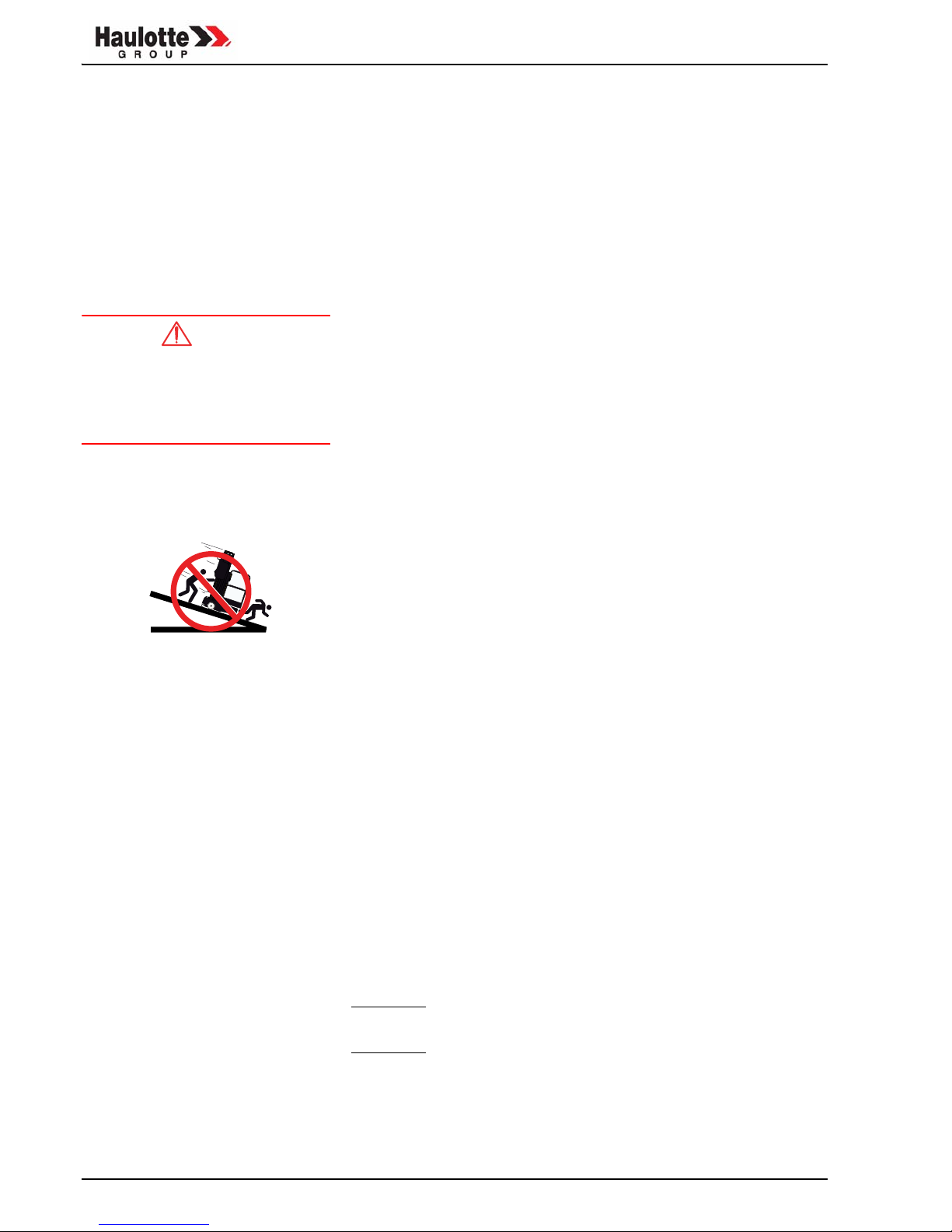
TO GO UP OR DOWN A SLOPE:
- TW O OPERATORS ARE RE QUIRED TO GO DOWN
SLOPES OF 5°. USE A LI FT TRUCK TO MOVE THE
MACHINE ON SLOPES OF MORE THAN 5°.
- IT IS ESSENTIAL TO MOVE UP OR DOWN A SLOPE WITH
THE END OF THE MACHINE PLAT FORM P OINTING
DOWNHILL. THE TWO O PERATORS MUST REMAIN
BESIDE THE QUICK UP TO GUIDE IT.

Operation and maintenance
21
4.2 - OPERATIONS BEFORE FIRST USE
REMINDER:Before any operation, get to know the machine by reading this
manual and the instructions marked on the various plates.
Before using the machine:
• Identify obstacles such as cranes, lifting equipment, construction machines in the working area.
• Make sure that operators of other overhead or ground level machines
are aware of the presence of the Quick Up.
• The operator must take the safety precautions necessary to avoid all
risks in the work area.
4.2.1 - "Mast" control panel
Photo 1: "Mast" control panel
1 - Mains light indicator 6 - Power on light indicator
2 - Battery light indicator 7 - Emergency lowering push button
3 - Platform/chassis control panel/machine stop selection
8 - Stabiliser bar OK light indicators
4 - Start push button 9 - Lowering light indicator
5 - Emergency stop push button
OK
307P220190 c
1
2
3
4
6
7
9
5
8

Operation and maintenance
22
Caution!
Caution!
4.2.2 - "Platform" control panel
Photo 2: Platform control panel
DURING HIGH PRESSURE
WASHING, DO NOT DIRECT THE
JET AT THE ELECTRIC BOXES AND
CABINETS
4.2.3 - Checks before use
• Make sure that the machine is on a flat, stable floor that can take the
weight of the machine
• Visually inspect the w hole machine for pain t ch ips, le aking ba ttery
acid, etc.
• Check that there are no loose bolts, nuts, connections or hoses, no oil
leaks, no broken or disconnected electric wires.
• Check the mast, chassis, stabilis er bars and platform : no v isible damage, no indications of wear or deformation.
• Check that there are no leaks, traces of wear or impact, scratches,
rust or foreign matter on the jack rods.
• Hydraulic unit and pump: no leaks, tight components.
• Check the level of hydraulic oil: top up if necessary.
• Check that the battery terminals are clean and tight: slack or corroded
terminals may result in a loss of power.
• Check battery charge: recharge if necessary.
These machines are not insulated
and must not be used near electric
lines.
• Check that the platform control panel power cable is in good condition.
• Check correct operation of the emergency stops.
• Check that the labels are clean and legible.
• Check that the wheels work properly.
• Visually check the underside of the chassis.
10 - Emergency stop button
11 - Up/down switch
12 - Start button
307P220200 c
12
11
10

Operation and maintenance
23
Caution!
4.3 - STARTING UP
IMPORTANT: Only start work after careful completion of all the
operations in the previous chapter.
REMINDER:The main control panel is in the platform.
In normal use, the "mast" control panel is used to check correct operation
and stabilisation of the machine. It is also an emergency control panel to
be used by a second operator if th e operator in the platform is unable to
get down (fainting, etc.).
The platform/mast panel selection key must be removed and kept on the
ground by a person present and trained in emergency/rescue manoeuvres.
4.3.1 - Power on
• Connect the battery or plug the machine in to the mains.
• Put the key in and turn the selector to the chassis position (ref. 3 Photo 1).
• Unlock the emergency stop button (ref. 5 Photo 1).
• The power light indicator (ref. 6 Photo 1) comes on.
• The mains or battery power light indicator (ref. 1 or ref. 2 Photo 1) comes on.
4.3.2 - Machine stabilisation
• Insert the stabiliser bars and ensure that they are properly locked with
the blocking pins.
• Move the stabilisation foot in either direction until the relevant light indicator comes on on the bottom control panel.
• When the machine is perfectly stable, the 4 light indicators are on.
4.3.3 - Up/Down
MAXIMUM LOAD:
QUICK UP 7, 8, 9, 11, 12, 13: 159 kg
QUICK UP 14: 136 kg
• Put the control panel selection key (ref. 3 Photo 1) in the platform position.
• Unlock the emergency stop button (ref. 7 Photo 1) on the bottom panel.
• In the pla tform, mo ve the switch to the up or down position (ref. 11
Photo 2), while holding down the start button (ref. 12 Photo 2).
• Release of the switch (ref. 11 Photo 2) or of the start button (ref. 12
Photo 2) interrupts movement.

Operation and maintenance
24
Caution!
Caution!
Caution!
Caution!
Climb into the basket, respecting
the maximum load
recommendations, distributing the
load over the whole floor if
necessary.
4.3.4 - Testing the platform control panel
Make sure there are no people or
obstacles under the platform before
lowering it.
• Make sure that the platform emergency stop button (ref. 10 Photo 2)
is enabled.
• If a movement is not made when commanded, push the emergency
stop button (ref. 10 Photo 2) then reset.
• Test the up/down movements (ref. 11 Photo 2).
4.3.5 - Stopping the machine
• Press the emergency stop button on the bottom panel (ref. 5 Photo 1).
• Put the key selector in the "NORMAL" position (ref. 3 Photo 1).
• Remove the key.
4.4 - EMERGENCY AND RESCUE OPERATIONS
4.4.1 - Emergency lowering
If the operator in the platform is no longer able to control the movements in
spite of the ma chine ope rating no rmally, a n au thorised op erator on the
ground can do so.
If the platform is trapped by
overhead structures or equipment,
the operator must be evacuated
from the platform before freeing the
Quick Up.
• Put the selector (ref. 3 Photo 1) in the chassis position.
• Press the emergency stop button (ref. 7 Photo 1).
• The platform moves down.
NOTE: 8 x LR6 batteries, inside the mast control pane l, take over
from the main batteries if they are discharged to enable lowering of the platform.
4.4.2 - Rescue lowering
If a disorder of operation prohibited to the user to go down the ground, an
authorised operator on the ground can do so:
• Turn the manual valve anti-clockwise.
• The platform moves down.
Remember to screw the valve back
into place once the platform
reaches the ground, otherwise the
machine will be lowered again the
next time it is raised.

Operation and maintenance
25
4.5 - USE AND MAINTENANCE OF BATTERIES
The b atteries pr ovide the po wer fo r you r p latform. When th ey ar e
discharged, the battery light indicator on the mast control panel flashes.
Here a re some tips to help yo u use the ba tteriese to the ir full cap acity
without risk of premature deterioration.
4.5.1 - Starting operation
• Check the electrolyte level.
• Do not force the batteries during the first few cycles. Ensure not to exceed discharges higher than 4 hours of use.
• The batteries will provide full capacity after about ten work cycles. Do
not add water before these ten cycles have been completed.
4.5.2 - Discharge
• Never discharge the batteries by more than 80% of their capacity in 3
hours.
• Never leave the batteries discharged.
4.5.3 - Charge
• When to recharge?
- after 3 hours of use or after a long period of inactivity.
• How to recharge?
- make sure the mains power is suitable to charger consumption,
- fill with electrolyte to the minimum level if the level of an element is
below this minimum,
- work in a clean, aired area, away from any naked flames,
- open the box covers,
- use the machine’s built-in charger. Its charge output is suited to
battery capacity.
• During charging
- do not remove or open the caps of the elements,
- make sure element temperature does not exceed 45°C (be careful
in summer or in areas where ambient temperature is high).
• After charging
- fill up with electrolyte if necessary.
4.5.4 - Servicing
• Never add acid (in the event of spillage, contact Aftersales).
• Never leave discharged batteries inactive.
• Avoid overflow.
• Clean the batteries to avoid salt formation and current drift.
• Wash the top without removing the caps.
• Dry with compressed air and wipe with clean cloths.
• Grease the terminals.
• Implement ade quate safety me asures f or b atteries servicing operations (wear protective gloves and goggles).
To enable rapid diagnosis of the state of your batteries, note the density of
each element once a month using a battery hydrometer, as a fun ction of
the temperature, using the graphs below (do not measure just after filling).

Operation and maintenance
26
Caution!
BATTERY CHARGE STATE AS A FUNCTION OF DENSITY AND TEMPERATURE
DO NOT PERFORM ELECTRIC ARC
WELDING ON THE MACHINE
WITHOUT FIRST DISCONNECTING
THE BATTERIES
IMPORTANT: DISCONNECT THE BATTERIES FIRST. NEVER TRY TO
USE THE BATTERIES TO START ANOTHER VEHICLE

Operation and maintenance
27
Caution!
Caution!
Caution!
Caution!
5 - MAINTENANCE
5.1 - GENERAL RECOMMENDATIONS
Before any intervention on the
machine, position it on a firm,
horizontal floor, fold it completely,
disconnect electric power and
depressurise the hydraulic circuit.
The maintenance operations indicated in this manual are given for normal
operating conditions.
In difficult co nditions: ex treme t emperatures, hig h hygrometry, po lluted
atmosphere, high alt itude, etc., certain o perations should b e car ried out
more frequently and specific precautions may be necessary. Consult the
manufacturer’s or distributor’s Aftersales service for more information.
Any technical intervention must be
performed by a HAULOTTE service
technician or an approved
HAULOTTE agent.
Only approved, skilled technic ians ma y intervene on the machine. They
must comply with the safety instructions co ncerning per sonnel an d
environmental protection.
Check correct operation of the safety systems before use.
Never work underneath a lifted
platform without first securing it
with wedges or overhead slings.
Caution!
Before straightening an overturned
machine, make sure it has not
suffered any damage that could
prevent it from standing correctly
on its wheels in the vertical
position. Use a crane, lift truck or
other machine and gradually bring
the Quick Up back to the vertical
position.
IMPORTANT: For any repair operation, use manufacturer certified
original parts. Any non compliance with this rule may incur serious
safety and stability risks for the machine.
IMPORTANT: For major maintenance operations requiring
dismounting of one or more of the machine’s components, contact
the manufacturer for specific recommendations to avoid any
dangerous situations.
After dismounting a component affecting the lifting structure, static
and dynamic tests must be performed before putting the machine
back into operation (see Chap. 1.4.2, page 5).
Do not use the machine as a
welding earth -
do not weld without disconnecting
the (+) and (-) terminals of the
batteries -
Do not start other vehicles with the
batteries connected.

Operation and maintenance
28
Caution!
After an incident, inspect the
machine carefully and test all the
functions. Only lift the platform after
checking that all damage has been
repaired and that all commands
work properly.
THE MANUFACT URER MU ST BE INFORMED
IMMEDIATELY OF ANY INCI DENT INVOLVING A QUICKUP, E VEN IF N O MATER IAL DAMAGE OR IN JURY IS
CAUSED.
5.1.1 - Periodical servicing
IMPORTANT: IF USING "ORGANIC" OR "EXTREME COLD" OIL, THE
PRERIODICITIES INDICATED BELOW SHOULD BE HALVED .
• Collect old oil to prevent environmental pollution.
NOTE: Maintenance personnel must refer to the requirements of lo-
cals standards, in regard to the general and 10 year inspection requirement which apply to this product.
PERIODICITY OPERATION
Before use • Check all the machine’s safety systems
Every day • Check:
- that the re are no oil le aks (traces o n the g round un der the
parked machine)
- that the mast pad slide paths are clean
- the condition of protections
- the condition of welding
- the electric connections and battery power cables
- the stabliser bars and their blocking pins
- the manual lowering valve
Every week • Visually check
- the battery level. If necessary, top up with distilled water, only
after charging
- the condition of the cables.
• If necessary, clean and/or oil the masts and cables.
Every 3 months • Check:
- battery density
-masts
-platform
- control boxes
- platform overload
• Oil the mast chains
• Check tightness of wheels, hydraulic connectors and bolts
Every 6 months • Change the batteries
Every year • Check:
- Perform a co mplete check of ma sts an d/or co ntact the
manufacturer and/or distributor
- Electric connections.
• Empty the hydraulic tank and change the oil.
• Have the machine examined by a certified inspection organisation (Order dated March 15th 2004)

Operation and maintenance
29
Caution!
Caution!
5.1.2 - Operating instructions
5.1.2.1 -Disassembly of Mast
1. Remove the mast just as like the previous mentioned.
2. Remove holding bolt fro m clevis blo ck a t the e nd o f cylin der r od fo r
raising.
3. Push carefully outward under part of mast supporting cylinder.
4. Turn carefully mast in order first column to be positioned behind.
5. Re move adjustable nut fr om sequence ca ble. Do wn sequence pulley
bracket and remove it.
6. Remove control box on working platform.
7. Release installation screw connecting box under part of mast. Remove
control cable from mast.
8. Remove adjust screw and rock nut from carrier chain terminal.
9. Push carrier outward to under part of mast and remove it.
Chain shall not be twisted. 10. Lay the chain on the upper part of mast.
11. Push up per colu mn upward in order to be ge t 30 cm a bove an d
assemble installation bolt of idle wheel.
12. Remove idle wheel for installation of wheel shaft plate at the upper part
of column.
13. Re move adju st nu t o f rock nu t a t the ch ain ter minal of up per pa rt of
column.
14. Push mast outward to under part of mast and lay down it.
Chain shall not be twisted. 15. Lay the chain down outside of column. Pick the chain and lay it on the
upper part of column.
16. Repeat 11 to 15 step for the rest.
Before de taching cha ins, the chains shall be ma rked for p revention of
misconnection.
Holding bolt
The first column
The second column
The third column
The first chain
T
he second chain

Operation and maintenance
30
Caution!
Caution!
5.1.2.2 -Assembly of mast
1. Remove seams under the roller wheel button and clean all the column.
2. Put first column on the supporting plate and put the chain on the upper
part.
3. Paste wax on outside and inside channel of column.
4. Push the second column into the inside of first column so that the upper
part of co lumn could contacts to the upper part of roller wheel at the first
column.
5. Spread grease on end of the roller bolt and button.
6. Install sea m on the u pper and middle part of roller wheel. Install roller
wheel button. Don't install lower roller button.
7. Push the second column into the chain column and inspect whether it is
placed in between.
8. The seam at the side for adjustment shall be identical and it will be fasten
so that it shall withstand the 6.8~9kg of loads.
9. Seam of roller wheel will be fasten so that it shall withstand the 6.8-9kg
of loads.
10. Repeat 3 to 9 step for the rest.
11. Remove all column from supporting plate in turn after supporting seam.
12. Install chain inside column and installation plate for chain fastening.
13. Put the chain in each column.
The chain shall not be contaminated
or twisted.
14. Put the chain in first column.
15. Push the second column into the first column in order to be get 30 cm
above the upper part of first column.
16. Install id le wh eel in upper p art of the seco nd column. Be sure to
securely installed and inspect it is smoothly rotated without moving 1mm to
the side. When it is worn so that it shall be changed, outside diameter shall
maintain equal distance.
The chain shall not be contaminated
or twisted.
17. Put the chain in second column.
18. Connect chains inside of the first and second column. The idle wheel in
the second column shall be located to be pulled up.
19. Push the third column into the second column in order to be get 30 cm
above the upper part of second column.
20. Install chain in the bracket of third column.
21. The second column is constrained by the first column.
22. Push the third column into the second column in order to be get 30 cm
above the upper part of second column.
23. Repeat 16 to 25 step for the rest column.
24. Press the second colu mn u ntil the bo ttom pa rt o f the fir st colu mn is
identical.
25. Increase the tension so that the chain connected to the end of rod has
the identical tension.
26. Install rock nut in 4th and 5th column.
27. Put the third column placed 5.08 cm projected.

Operation and maintenance
31
28. Push carrier under the mast.
29. Adjust the end of chain rod until the bottom of the third column contacts
the reference line of the second column. Tension of rod at the end of chain
shall be identical.
30. Install rock nut at the third column. There shall be no shake.
31. Repeat 29 to 30 for the rest of column.
32. Push the third column 15.2 cm ahead.
33. Install idle wheel plate as the same level of column.
5.1.2.3 -Adjustment of raising chain
1. Lower th e m achinery completely an d adjust the distance as sp ecified
after measuring the spa ce between th e bo ttoms of second an d th ird
column.
2. Raise the working platform 2 mm high.
3. Release rock nut at the end of chain rod in the third column.
4. Turn nut at the chain end clockwise or counterclockwise in order to be
strong. Lock rock nut.
5. Lo wer the ma chine comp letely and ad just the chain as specified after
measuring the space between the bottoms of third and fourth column.
6. Adjust the rest as the same method.
5.1.2.4 -Electric batteries
• Disconnect the battery.
• Remove the battery from its support.
The third column
Base

Operation and maintenance
32

Operation and maintenance
33
6 - OPERATING INCIDENTS
REMINDER:Compliance with the mach ine’s o perating a nd maintenance
instructions will avoid most incidents.
However, if an incident does occur, before any intervention, check the table
below for information and follow the instructions.
Only common incidents that can be solved by the operator are mentioned.
For a ny othe r incid ent, co ntact your HAULOT TE age nt or th e
manufacturer’s Aftersales service.
Before diagnosing a failure, check that:
• the mast and platform emergency stop buttons are unlocked
• the batteries are properly charged.
INCIDENTS PROBABLE CAUSES SOLUTION
No movement from the
platform
• Mast key selector in the wrong po sition
• Platform overload
• Lifting button operating fault
• Panel power cable damaged
• Batteries discharged
• Check cable voltage
• ·Put in platform position
• Remove load
• Replace the button
• Repair or replace the cable
• Recharge the batteries
• Repair or replace the cables
Electropump no t
working
• Reset button not working
• Defective or discharged batteries
• The battery cable is not making contact
• Check tightness of the power cables
• Repair or replace the contactor
• Replace or recharge the batteries
• Clean and tighten the terminals
Insufficient pressure or
power
• Hydraulic pump not working properly
• Unit pressure regulation screw requires calibration
• Oil leak on connector, hose o r component
• Hydraulic unit fault ·
• Repair or replace the pump
• Calibrate (contact Aftersales)
• Repair or replace·
• Replace the unit· (contact Aftersales)
Noisy hydraulic pump • Insufficient oil in the tank
• Broken or loo se ho se or co nnector
(suction side)
• Fill up
• Repair, tighten or replace

Operation and maintenance
34

Operation and maintenance
35
7 - HYDRAULIC DIAGRAM
7.1 - AC VERSION

Operation and maintenance
36
7.2 - DC VERSION

Operation and maintenance
37
8 - WIRING DIAGRAMS
8.1 - AC VERSION

Operation and maintenance
38
8.2 - DC VERSION

39
9 - REGISTER OF INSPECTION AND REPAIR
Date Comments

40
Date Comments
 Loading...