

Haulotte 45XA, HLA16PX Operator's Maintenance Manual
OPERATOR’S & MAINTENANCE
MANUAL
B33-01-0104 Rev. 4 August 2012

HAULOTTE GROUP
SELF-PROPELLED AERIAL WORK PLATFORM
This equipment is designed and manufactured in compliance with the duties, responsibilities and
standards set forth for manufacturers in the ANSI, CSA, AS and / or CE standards in effect at the time
of manufacture.
This equipment meets or exceeds applicable ANSI, CSA, AS and / or CE codes and standards when
operated in accordance with manufacturer’s recommendations.
It is the responsibility of the user to follow all Federal, State, and Local codes and regulations that
govern the safe operation of this equipment.
Obtain, read and obey all safety precautions before performing maintenance or repairs or
attempting to operate this equipment.
all Federal, State, and Local codes and regulations.
To ensure proper and safe use of this equipment, it is strongly recommended that only trained and
authorized personnel attempt to operate and maintain the aerial work platform. Some countries
require that operators are licensed to operate aerial work platforms. Check with all Federal, State, and
Local codes and regulations before operation this machine.
This manual shall be considered a permanent and necessary component of the aerial work platform
and shall be kept with the machine at all times.
Owners and Lessors should complete a full inspection of all components and perform a test of all
functions, including brake functions, before commissioning or reselling the aerial work platform. Repair
or replace all damaged or malfunctioning components. Check local requirements with your manager.
This includes all manufacturer recommendations as well as
Haulotte Group is dedicated to the continuous improvement of this and all Haulotte Group products.
Therefore, equipment information is subject to change without notice. Direct any questions or
concerns regarding errors and / or discrepancies in this manual to the Haulotte Group Customer
Service Department: at 1-800-537-0540 or visit Haulotte Group online at www.haulotte-usa.com.
CALIFORNIA
Proposition 65 Warning
Diesel engine exhaust and some of its constituents are
known to the State of California to cause cancer, birth
defects, and other reproductive harm.
2

HAULOTTE GROUP
TABLE OF CONTENTS
1 SAFETY …………………………………………………………………………………………………….7
LEGEND: SAFETY ADVISORIES...................................................................................................7
BEFORE OPERATION.....................................................................................................................8
DURING OPERATION .....................................................................................................................9
DRIVE SAFETY..............................................................................................................................11
FALL PROTECTION ......................................................................................................................11
MANUAL FORCE...........................................................................................................................12
WIND LOADING.............................................................................................................................12
EXPLOSION HAZARD...................................................................................................................12
MAINTENANCE .............................................................................................................................13
2 SPECIFICATIONS..........................................................................................................................15
RANGE OF MOTION .....................................................................................................................15
SPECIFICATIONS..........................................................................................................................16
WARRANTY - NEW PRODUCT; HAULOTTE NORTH AMERICA ................................................18
WARRANTY CLAIMS PROCEDURE.............................................................................................19
DAMAGED EQUIPMENT POLICY.................................................................................................20
3 OPERATION...................................................................................................................................21
GROUND (LOWER) CONTROL PANEL........................................................................................22
PLATFORM (UPPER) CONTROL PANEL.....................................................................................25
JOYSTICK - PLATFORM (UPPER) CONTROL PANEL................................................................28
NORMAL OPERATING PROCEDURE..........................................................................................29
DRIVE FUNCTION.........................................................................................................................32
MANUAL BRAKE RELEASE..........................................................................................................32
MANUAL BOOM OPERATION.......................................................................................................33
LIFTING THE AERIAL WORK PLATFORM...................................................................................35
TRANSPORTING THE AERIAL WORK PLATFORM ON TO A TRUCK BED...............................36
4 EQUIPMENT MAINTENANCE.......................................................................................................37
BATTERY RECHARGE..................................................................................................................38
BATTERY FAULT CODES.............................................................................................................39
DAILY SERVICE CHECKS ............................................................................................................40
WEEKLY SERVICE CHECKS........................................................................................................43
MONTHLY SERVICE CHECKS .....................................................................................................44
ANNUAL SERVICE CHECKS ........................................................................................................45
STRUCTURAL INSPECTION ........................................................................................................47
MOTOR DRYING INSTRUCTIONS ...............................................................................................47
LEVELING SYSTEM CALIBRATION PROCEDURE .....................................................................48
OVERLOAD PROTECTION CALIBRATION PROCEDURE..........................................................50
ADDITIONAL SERVICE INFORMATION.......................................................................................53
MANUAL OUTRIGGER RETRACTION..........................................................................................54
HYDRAULIC PRESSURE GAUGE................................................................................................55
TROUBLESHOOTING ...................................................................................................................56
ERROR CODE DEFINITIONS – CONTROLS................................................................................57
ERROR CODE DEFINITIONS – MOTOR CONTROLLER.............................................................68
5 CYLINDER REPLACEMENT.........................................................................................................71
MASTER / SLAVE CYLINDER REPLACEMENT...........................................................................71
LIFT CYLINDER REPLACEMENT.................................................................................................73
OUTRIGGER CYLINDER REPLACEMENT...................................................................................75
6 DECAL REPLACEMENT ...............................................................................................................77
DECAL KIT - ANSI .........................................................................................................................78
ID E N T I F I CAT I O N P L ATE S & OPT I O N A L EQU I P MEN T - A N S I............................................................80
DECALS - ANSI..............................................................................................................................82
3

HAULOTTE GROUP
7 OPTIONAL EQUIPMENT ...............................................................................................................87
MATERIAL LIFT HOOK.................................................................................................................88
PLATFORM ROTATOR.................................................................................................................91
8 MATERIAL SAFETY.......................................................................................................................93
LEAD ACID BATTERIES, WET, FILLED WITH ACID – UN 2794................................................. 93
POWERFLOW™ AW HVI HYDRAULIC OIL.................................................................................98
9 ANSI REPRINT.............................................................................................................................105
INSPECTION FORM FOR HAULOTTE AERIAL WORK PLATFORMS ..........................................117
LIST OF TABLES
TABLE 1-1. MINIMUM SAFE APPROACH DISTANCES .....................................................................9
TABLE 1-2. BEAUFORT SCALE ........................................................................................................12
TABLE 4-1. BATTERY CHARGER FAULT CODES...........................................................................39
TABLE 4-2. TROUBLE SHOOTING....................................................................................................56
TABLE 4-3 ERROR CODE DEFINITIONS.........................................................................................57
TABLE 4-4. ERROR CODE DEFINITIONS - MOTOR CONTROLLER ..............................................68
TABLE 9-1. MINIMUM SAFE APPROACH DISTANCES .................................................................115
4

HAULOTTE GROUP
LIST OF ILLUSTRATIONS
Figure 2-1. Range of Motion............................................................................................................15
Figure 3-1. Ground (Lower) Control Panel ....................................................................................22
Figure 3-2. Platform (Upper) Control Panel...................................................................................25
Figure 3-3. Platform Controls Joystick..........................................................................................28
Figure 3-4. Boom Travel Latches ...................................................................................................29
Figure 3-5. Outrigger Control Panel...............................................................................................30
Figure 3-6. Drive Speed Selector....................................................................................................32
Figure 3-7. Manual Break Release..................................................................................................32
Figure 3-8. Hand Pump Controls for Manual Operation...............................................................33
Figure 3-9. Location of Lift Cylinders for Manual Boom Lowering.............................................34
Figure 3-10. Location of Manual Lowering Valves..........................................................................34
Figure 3-11. Lifting the Aerial Work Platform..................................................................................35
Figure 3-12. Transport the Aerial Work Platform............................................................................36
Figure 4-1. Battery Charger Faceplate...........................................................................................38
Figure 4-2. Outrigger Position Switch............................................................................................41
Figure 4-3. Hydraulic Reservoir......................................................................................................42
Figure 4-4. Wheel Nut Tightening Sequence.................................................................................44
Figure 4-5. Display Run Time Hours..............................................................................................45
Figure 4-6. Machine Position for Slew Ring Measurement..........................................................46
Figure 4-7. Slew Ring Position Measurement ...............................................................................46
Figure 4-8. Platform Position After Rotation.................................................................................46
Figure 4-9. Position Machine for Leveling.....................................................................................48
Figure 4-10. Level Sensor Digitally Based.......................................................................................48
Figure 4-11. Level Sensor Pendulum Based...................................................................................48
Figure 4-12. Ground (Lower) Control Panel for Leveling System .................................................49
Figure 4-13. Platform Position..........................................................................................................50
Figure 4-14. Ground (Lower) Control Panel for Overload Protection ...........................................50
Figure 4-15. Manual Outrigger Control Wire Harness ....................................................................54
Figure 4-16. Bottom Side of the Ground (lower) Control Box. ......................................................54
Figure 4-17. Hydraulic Power Unit....................................................................................................54
Figure 4-18. Attaching the Pressure Gauge to the Hydraulic Power Unit. ...................................55
Figure 4-19. Motor Controller............................................................................................................68
Figure 5-1. Location of Master Cylinder ........................................................................................71
Figure 5-2. Location of Slave Cylinder...........................................................................................72
Figure 5-3. Location of Manual Lowering Valves for Lift Cylinder Replacement ......................73
Figure 5-4. Push “Button” Lowering Valve ...................................................................................73
Figure 5-5. Lift Cylinder Replacement ...........................................................................................73
Figure 5-6. Outrigger Cylinder Replacement.................................................................................75
Figure 5-7. Cylinder Valve Removal...............................................................................................75
Figure 7-1. Disconnect Plug from Load Sense Module................................................................88
Figure 7-2. Remove Platform (Upper) Control Box.......................................................................88
Figure 7-3. Loopback plug..............................................................................................................88
Figure 7-4. Platform Removal.........................................................................................................89
Figure 7-5. Material Lifting Hook Installation ................................................................................89
Figure 7-6. Material Lift “Stowed” Position...................................................................................90
Figure 7-7. Material Lift “In Use” Position.....................................................................................90
Figure 7-8. Manual Platform Rotator..............................................................................................91
Figure 9-1. Minimum Safe Approach Distance............................................................................114
5
HAULOTTE GROUP
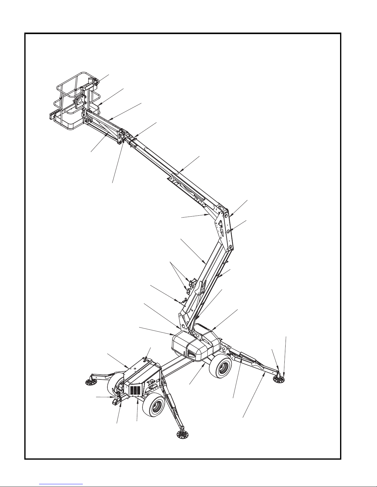
PRIMARY MACHINE COMPONENTS
JIB LIFT
CYLINDER
SLAVE
CYLINDER
PLATFORM CONTROL BOX
PLATFORM
JIB BOOM
EXTENSION
BOOM
SECONDARY BOOM
KNUCKLE
POWER UNIT
COMPARTMENT
ENGINE
COMPARTMENT
PRIMARY
BOOM REST
LIFT CYLINDER
PRIMARY BOOM
FORK LIFT
POCKETS
SECONDRY
BOOM REST
TURNTABLE
SECONDARY
.
FUEL
TANK
REAR
AXLE
MASTER
CYLINDER
LOWER LINK
PRIMARY
LIFT CYLINDER
GROUND
CONTROL BOX
OUTRIGGER
PAD
OUTRIGGER
FOOT
OUTRIGGER
CYLINDER
BOOM
LATCH
6
FRONT
AXLE
OUTRIGGER
LEG
HAULOTTE GROUP 1 SAFETY
1 SAFETY
Proper training is required for the safe operation of any mechanical device. Failure to follow all
instructions and safety precautions in this manual and attached to the aerial work platform will result
in death or personal injury.
Prior to Operation:
Read, understand and obey all instructions and safety precautions in this manual and attached to
the aerial work platform.
Read, understand and obey all Federal, State and Local codes and regulations.
Become familiar with the proper use of all controls.
Inexperienced users should receive instruction by a qualified instructor before attempting to
operate or maintain the aerial work platform.
The use of intelligence and co mmon sens e is the b est pr actic e when follo wing an y safety policy .
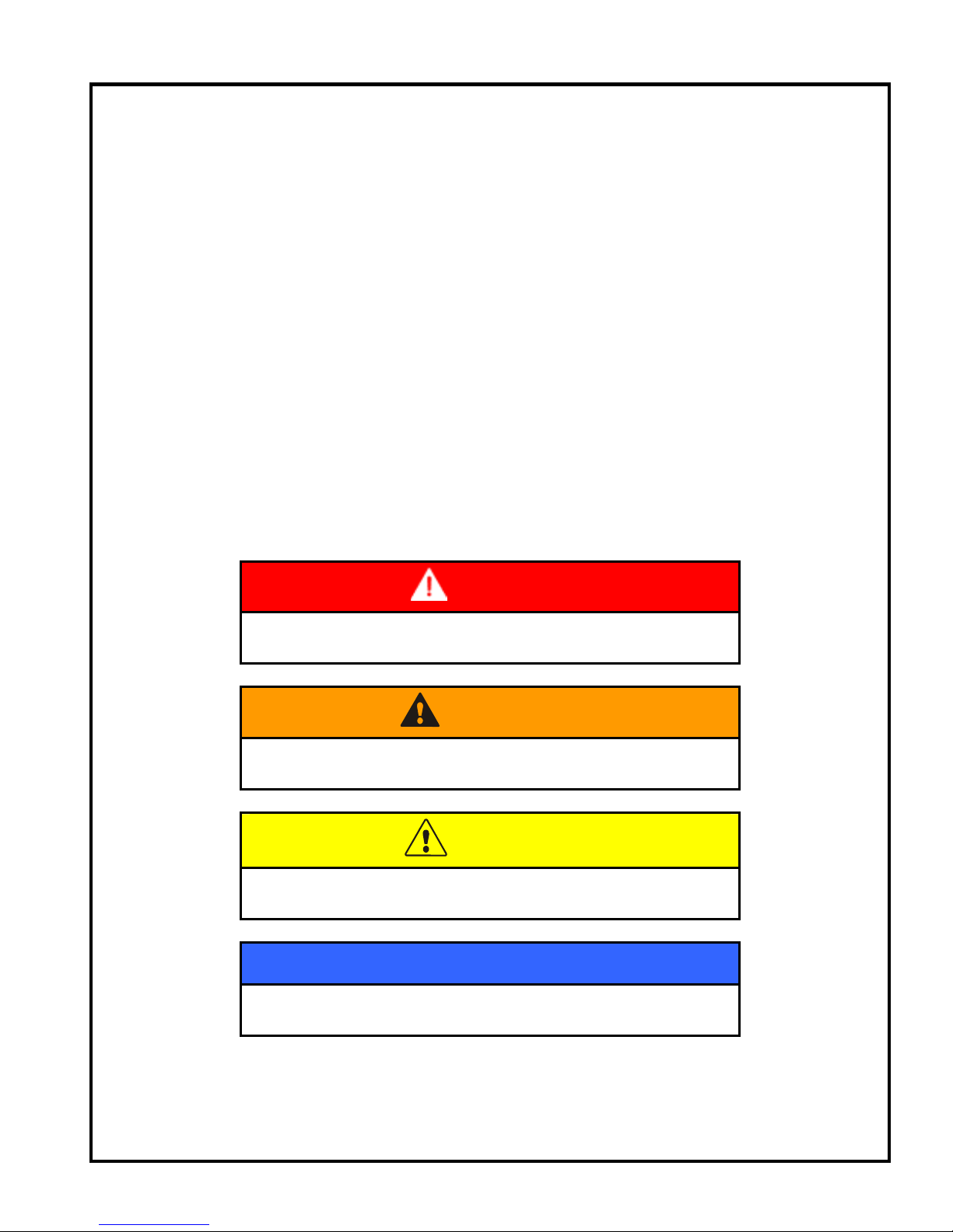
LEGEND: SAFETY ADVISORIES
The following safety advisories are used throughout this manual to indicate specific hazards when
operating or maintaining the aerial work platform. Read, understand and obey all safety advisories to
prevent improper service, damage to equipment, personal injury or death.
DANGER
Indicates a hazardous situation which if not avoided, will
result in death or serious injury
.
WARNING
Indicates a hazardous situation which if not avoided, could
result in death or serious injury
.
CAUTION
Indicates a hazardous situation which, if not avoided, may
result in minor or moderate injury.
NOTICE
Contains information important in the prevention of errors
that could damage the machine or its components
.
NOTE: Contains additional information important for
performing a procedure.
7

HAULOTTE GROUP 1 SAFETY
BEFORE OPERATION
Ensure the following general safety precautions are followed before operating the aerial work
platform:
ALWAYS inspect the usage area for potential hazards, such as unstable or unlevel surfaces,
overhead obstructions and electrically charged wires or conductors. ALWAYS watch for moving
vehicles in the operating area.
ALWAYS conduct a thorough visual inspection of the aerial work platform before operation. Check
for damaged or worn parts, hydraulic leaks, damaged wiring, loose wiring conductors, damaged
outriggers, low tire pressure, uneven tire wear or tire damage. Check for any improperly operating
components. NEVER operate the aerial work platform if any damage is observed or suspected.
Repair damaged or malfunctioning equipment before operation.
ALWAYS wear proper clothing. Wear protective equipment as required by Federal, State and Local
codes and regulations. Keep loose clothing, jewelry, gloves and hair away from moving parts.
ALWAYS wear a Safety Harness and energy-absorbing Lanyard, such as the Safety Harness and
Lanyard available through the Haulotte Group.
ALWAYS inspect platform floor and outrigger footpads for mud, grease, debris or other foreign
material. ALWAYS remove any such material from the aerial work platform before operation.
ALWAYS RED tag any part of this machine known or suspected to be damaged or malfunctioning.
ALWAYS remove a malfunctioning, damaged or defective aerial work platform from service. NEVER
operate an aerial work platform that has any known or suspected defect.
ALWAYS comply with the instructions found in Safety and / or Service Bulletins distributed by the
manufacturer / factory. Bulletins may contain critical procedures that supersede the information
contained in this manual.
NEVER operate this aerial work platform while under the influence of drugs or alcohol, while taking
prescription medications that may leave the operator drowsy or prone to dizziness, or while feeling ill.
NEVER modify, alter or change the aerial work platform in any way that would affect its original
design or operation.
NEVER deface, modify or obscure any decals or markings on the aerial work platform.
NEVER operate this aerial work platform in any way for which it is not intended.
NEVER operate this aerial work platform in explosive or flammable environments.
Before attempting aerial work platform operations, operator(s) should:
Attend a training program as required by all Federal, State, and Local codes and regulations.
Obtain, read and obey all safety precautions as indicated by manufacturer’s recommendations
and all Federal, State and Local codes and regulations.
Become familiar with the location and use of all controls.
Verify that there are no overhead obstructions or live power sources in the work area that could
interfere with the safe operation of the aerial work platform.
Cordon off the area surrounding the aerial work platform to keep personnel, vehicles and moving
equipment away from the aerial work platform while in use.
Position the aerial work platform on a firm and level surface.
Conduct a pre-operation inspection by performing all recommended daily service checks.
Refer to the “Equipment Maintenance” section of this manual.
8
HAULOTTE GROUP 1 SAFETY
DURING OPERATION
Ensure the following general safety precautions are followed while operating the aerial work platform:
ALWAYS position away from power lines, this ensures that no part of the aerial work platform
accidentally reaches into an unsafe area. This includes full extension of the telescoping boom
through 700º of Non-Continuous rotation.
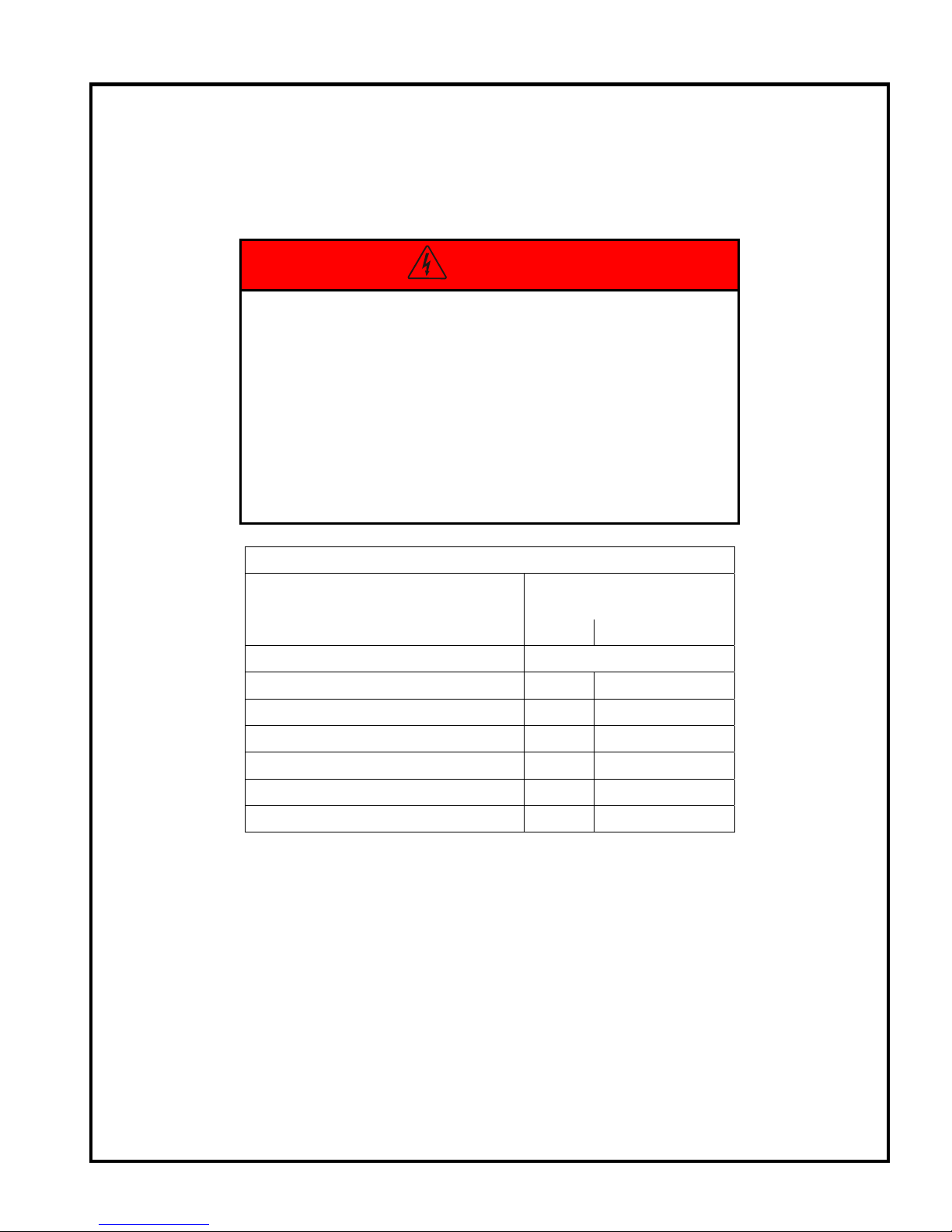
DANGER
This aerial work platform is NOT insulated for use near
electrical power lines and DOES NOT provide protection
from contact with or close proximity to any electrically
charged conductor. Operator must maintain safe
clearances at all times (10 ft (3.05 m) minimum) and must
always allow for Platform movement due to gusty winds.
Always contact power company before working near
power lines. Assume every power line is live. Power lines
can be blown by the wind.
Refer to Table 1-1 for minimum safe approach distances
between the machine and electrical power lines.
TABLE 1-1. MINIMUM SAFE APPROACH DISTANCES
Minimum Safe Approach
Voltage Range
(Phase to Phase)
(Feet) (Meters)
Distance
0 to 300V Avoid Contact
Over 300V to 50KV 10 3.05
Over 50KV to 200KV 15 4.60
Over 200KV to 350KV 20 6.10
Over 350KV to 500KV 25 7.62
Over 500KV to 750KV 35 10.67
Over 750KV to 1000KV 45 13.72
ALWAYS check with local electrical authorities regarding any local requirements which may differ
from those shown in Table 1-1.
ALWAYS keep away from an aerial work platform that is exposed to electrically charged power lines.
If the aerial work platform comes in contact with electrically charged power lines, NEVER touch or
operate the aerial work platform from ground level until power lines are shut off.
ALWAYS operate only on a firm and level surface. NEVER operate on surfaces that do not support
the aerial work platform with its rated load capacity, or on surfaces that do not support force exerted
by the outriggers during aerial work platform operation. Operate only on surfaces that can support a
pressure of 25 psi (1.8 kg/cm
2
) to ensure safe operation.
ALWAYS keep personnel away from potential pinch and shear points and from potential crush
hazards as indicated by decals attached to the aerial work platform.
ALWAYS keep the safety bar lowered (closed) unless personnel are entering or exiting the work
platform.
9

HAULOTTE GROUP 1 SAFETY
DURING OPERATION (CONTINUED)
ALWAYS use a three (3) point contact (both hands and one foot) when entering or exiting the work
platform.
ALWAYS wear proper footgear. ALWAYS keep the platform free of debris.
ALWAYS keep personnel and obstructions clear of the aerial work platform when repositioning the
boom or platform.
ALWAYS cordon the area surrounding the outriggers to keep personnel, vehicles and moving
equipment away from the aerial work platform while in use.
ALWAYS stay clear of overhead obstructions, including wires and cables.
ALWAYS disengage aerial work platform travel latches before raising aerial work platform sections
and reengage aerial work platform travel latches before transporting.
ALWAYS exercise caution when rotating the boom from the ground (lower) control panel. ALWAYS
watch for personnel inside the radius of the turntable and boom arm when rotating from the ground
(lower) or platform (upper) controls.
ALWAYS remove personnel from the aerial work platform before attempting to free an elevated
platform that has become caught or snagged on an adjacent structure or obstacle.
NEVER operate the aerial work platform from a position on a truck-bed, trailer, floating vessel or
scaffolding without written approval from the manufacturer / factory.
ALWAYS maintain joystick enable lever during drive operation.
NEVER allow electrode contact with any part of the aerial work platform while welding from the
platform. NEVER use the aerial work platform as a ground for welding.
NEVER operate without the outriggers fully extended or when the aerial work platform is not level.
NEVER position an elevated platform against another object to steady the platform.
NEVER override or bypass the manufacturer’s safety devices.
NEVER attach a safety harness to an adjacent structure, pole, or to nearby equipment while working
from the platform.
NEVER raise the outriggers with materials or personnel on board, or while platform is raised or
extended.
NEVER sit, stand or climb on platform railing. ALWAYS keep both feet firmly on the platform floor.
NEVER attempt to increase the working height with boxes, ladders, stools or any other materials.
NEVER operate this aerial work platform when exposed to high winds, thunderstorms, ice or any
weather conditions that would compromise operator safety.
NEVER operate aerial work platform in conditions where wind speeds exceed 28 mph (12.5 m/sec or
45 km/h). Steady or gusty winds that exceed the recommended wind speed may affect stability and
aerial work platform operation.
NEVER allow ropes, electric cords, hoses or other equipment to become entangled in the aerial work
platform.
NEVER exceed the load limits set by the manufacturer / factory. Use only the material lifting hook,
supplied as an option and manufactured by Haulotte Group when lifting materials. Safely stow all
tools and equipment.
10
HAULOTTE GROUP 1 SAFETY
DURING OPERATION (CONTINUED)
NEVER exceed load ratings by transferring loads to the aerial work platform at elevated heights.
NEVER use the platform to lift a load that exceeds the platform dimensions. NEVER lift a load in
such a way that the center of gravity is higher than the top guardrail of the platform.
NEVER modify the platform or carry materials that would increase the surface area of the platform.
Increasing the area exposed to the wind may affect the aerial work platform stability. NEVER attach
overhanging loads when raising or lowering the platform.
NEVER use the boom or platform to push or pull or to lift any part of the machine.
NEVER use the boom or platform to place a load against any structure, materials or equipment.
NEVER climb on the boom.
NEVER leave an elevated platform unattended.
NEVER leave the keys in the aerial work platform while unattended or not in use.
DRIVE SAFETY
ALWAYS maintain an awareness of limited sight and blind spots when operating drive functions.
ALWAYS limit travel speed according to surface conditions, slope, location of personnel and
obstructions and any other factors which may result in collision.
NEVER operate drive functions on slopes exceeding 45% (24°).
NEVER engage in stunt driving, horseplay or any other behavior considered unsafe according to
employer, job site and all Federal, State, and Local codes and regulations.
NEVER operate the internal combustion engine in an area that is not properly ventilated.
NEVER fuel the internal combustion engine while smoking, or while near spark or open flame.
FALL PROTECTION
Occupants must wear a safety belt or harness in accordance
with all Federal, State, and Local codes and regulations. Attach
lanyard to the anchor provided on the work platform.
Never sit, stand, or climb on the platform guard rails. Maintain
a firm footing on the platform floor at all times.
Never climb down from the platform when raised. If a power
failure should occur, ground personnel should use the manual
controls to lower the platform. Refer to the “Operation” section
of this manual for manual operation.
Keep platform floor clear of debris.
Lower the platform entry mid-rail or close the entry gate before
operating
.
11

HAULOTTE GROUP 1 SAFETY
MANUAL FORCE
Never push off or pull toward any object outside the platform.
Maximum allowable manual force is 90 lb. (400 N).
WIND LOADING
Never operate the aerial work platform in strong or winds that exceed 28 mph (12.5 m/s) or 45
km/h). Never increase the surface area of the platform or the load. Increasing the area exposed
to the wind will decrease the aerial work platform stability.
The Beaufort scale of wind force is accepted internationally and is used when communicating
weather conditions. It consists of a number 0-10>, each representing a certain strength or velocity
of wind at 33 ft (10 m) above ground level in the open. Refer to Table 1-2
TABLE 1-2. BEAUFORT SCALE
Description of wind Specifications for use on land m/h km/hr m/s
0 Calm Calm; smoke rises vertically.
1 Light Air Direction of wind shown by smoke.
2 Light Breeze Wind felt on face; leaves rustle; ordinary
vanes moved by wind.
3 Gentle Breeze Leaves and small twigs in constant motion;
wind exceeds light flag.
4 Moderate Breeze Raises dust and loose paper; small
branches are moved.
5 Fresh Breeze Small trees in leaf begin to sway; crested
wavelets form on inland waterways.
6 Strong Breeze Large branches in motion; whistling heard
in telephone wires; umbrellas used with
difficulty.
7 Near Gale Whole trees in motion; inconvenience felt
when walking against wind.
8 Gale Breaks twigs off trees; generally impedes
progress.
9 Strong Gale Slight structural damage occurs (chimney
pots and slates removed).
10> Storm, Violent
Storm, Hurricane
Trees uprooted, widespread damage to
structures, widespread devastation
1
1-3
4-7 6-11 1.6-3.3
8-12 12-19 3.4-5.4
13-17 20-28 5.5-7.9
18-24 29-38 8.0-10.7
25-30 39-49 10.8-13.8
31-38 50-61 13.9-17.1
39-46 62-74 17.2-20.7
47-54 75-88 20.8-24.4
55> 89> 24.5>
0-1 0-0.3
1-5 0.3-1.5
EXPLOSION HAZARD
NEVER operate aerial work platform if you smell or detect Liquid Petroleum Gas (LPG), gasoline,
diesel fuel or other explosive substances.
ALWAYS charge Batteries in an open, well-ventilated area away from sparks, flames and lighted
tobacco.
If this aerial work platform is equipped with a generator:
NEVER refuel with the engine running.
NEVER operate engine unless in a well-ventilated area to avoid carbon monoxide poisoning.
12

HAULOTTE GROUP 1 SAFETY
MAINTENANCE
Ensure the following general safety precautions are followed while performing maintenance on the
aerial work platform:
General Maintenance
ALWAYS perform maintenance procedures according to manufacturer’s guidelines. NEVER
disregard or bypass proper maintenance procedures.
ALWAYS inspect hydraulic system to ensure that all lines, connectors and fittings are properly
fastened and are in good condition.
ALWAYS turn the key switch to the “
OFF” position and remove key before performing maintenance.
Whenever possible, ALWAYS perform maintenance with the boom and platform in a fully lowered,
“stowed” position.
ALWAYS secure the boom before performing maintenance on hydraulic cylinders.
ALWAYS disconnect power to the hydraulic pump drive motor before making electrical checks to the
hydraulic valves.
ALWAYS keep all mechanical parts properly adjusted and lubricated according to maintenance
schedule and manufacturer / factory specifications. Refer to the “Equipment Maintenance” section of
this manual.
ALWAYS perform a function check of operating controls before each use and after any repairs have
been made.
ALWAYS locate and protect against possible pinch points before performing any maintenance or
repairs. Be aware of personnel under, and around the aerial work platform.
ALWAYS use only manufacturer-approved parts to repair or maintain aerial work platform. If any
portion of this aerial work platform is rebuilt or repaired, retesting is required in accordance with
manufacturer / factory instructions.
ALWAYS maintain a safe distance while testing the hydraulic components. ALWAYS relieve
hydraulic pressure before loosening or removing hydraulic components. NEVER test or operate the
hydraulic components while personnel are near the aerial work platform.
NEVER allow water or foreign particles into the DC electric motor housing. Inclusion of water or
foreign particles may cause serious damage to the motor. If the motor becomes wet, refer to the
“Motor Drying Instructions” located in the Equipment Maintenance section of this manual, or contact
the Haulotte Customer Service Department: at 1-800-537-0540 for proper drying instructions.
NEVER add unauthorized fluids to the hydraulic system or battery. NEVER mix hydraulic oils.
Consult manufacturer specifications. Refer to the “Equipment Maintenance” section of this manual
for hydraulic system maintenance procedures. Refer to the next page for Battery maintenance.
NEVER exceed the manufacturer’s recommended relief valve settings.
NEVER touch or allow metal tools to contact any components that are sensitive to static discharge.
ALWAYS use static discharge prevention mats and grounding devices when handling electronic
components.
NEVER adjust, repair, replace or bypass any hydraulic or electrical control or safety device. These
include, but are not limited to; hydraulic load control and flow control valves, solenoid valves and limit
switches. ALWAYS consult an authorized Haulotte Group technician by contacting the Customer
Service Department: at 1-800-537-0540 if repairs are necessary.
NEVER modify, alter or change the aerial work platform without first consulting an authorized
Haulotte Group technician, and NEVER in any way that would affect its original design or operation.
13

HAULOTTE GROUP 1 SAFETY
MAINTENANCE (CONTINUED)
Battery Maintenance
Ensure the following general safety precautions are followed when performing battery maintenance
on the aerial work platform:
ALWAYS check the battery fluid level daily.
ALWAYS wear safety glasses when working with or near batteries.
ALWAYS avoid contact with battery acid. Battery acid causes serious burns and should be kept
away from skin or eyes. If contact occurs, flush with water and consult a physician immediately.
ALWAYS disconnect ground cable first when removing battery.
ALWAYS connect ground cable last when installing battery.
ALWAYS charge batteries in open, well-ventilated areas.
ALWAYS replace batteries using only parts recommended by manufacturer / factory. ALWAYS use
only batteries with sealed caps over cells.
NEVER smoke while servicing batteries.
NEVER charge batteries near flammable materials.
NEVER allow batteries to overcharge and boil.
NEVER short across battery posts to check for current. NEVER break a live circuit at the battery.
NEVER disconnect battery from charger while charger is connected to a live power source.
NEVER jump-start other vehicles using the aerial work platform batteries.
14
HAULOTTE GROUP 2 SPECIFICATIONS
2 SPECIFICATIONS
The following information is based on ideal working conditions. Machine performance may vary
based on work environment and on machine options.
Only one telescoping boom motion is permitted at a time and only as long as the telescoping boom is
within the safe operating zone. When a selected telescoping boom motion exceeds a safe operating
limit, the telescoping boom motion ceases and another telescoping boom motion must be selected
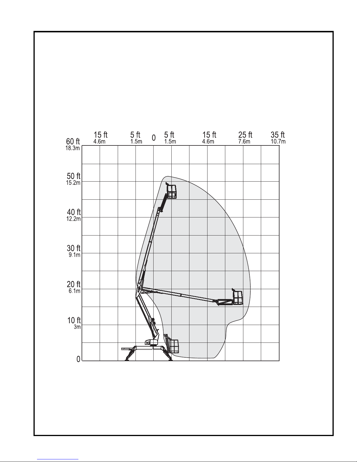
within the safe operating zone. Refer to Figure 2-1.
RANGE OF MOTION
Figure 2-1. Range of Motion
15

HAULOTTE GROUP 2 SPECIFICATIONS
SPECIFICATIONS
Maximum Working Height
Maximum Platform Height
Up and Over Height
Maximum Horizontal Outreach
From Centerline of Rotation 27 ft 0 in (8.2 m)
From Outrigger Footpad Edge 21 ft 0 in (6.4 m)
Rated Platform Capacity
Without Platform Rotation 500 lb (227 kg)
With Platform Rotation 440 lb (200 kg)
Maximum Number of Occupants
Total Weight
Turntable Rotation
Leveling Capability
Wheel Base
Turning Radius
Inside 11 ft 0 in (3.4 m)
Outside 16 ft 8 in (5.0 m)
Platform Dimensions
Height 3 ft 7 in (1.1 m)
Length 2 ft 6 in (0.8 m)
Width 5 ft 0 in (1.5 m)
Platform Rotation / Type (Optional)
Stowed Dimensions
Height 6 ft 7 in (2.1 m)
Length 18 ft 2 in (5.5 m)
Width 5 ft 6 in (1.7 m)
Jib Dimensions
Length 4 ft 3 in (1.3 m)
Vertical Motion 150° (+70° / -80°)
Outrigger Footprint (To Center of Pad)
Length 12 ft 4 in (3.8 m)
Width 11 ft 4 in (3.5 m)
Footpad Diameter 12.5 in (0.3 m)
Brake
Maximum Drive Speed
DC 1.75 mph (3 km/h)
IC 3.5 mph (6 km/h)
Gradeability
Tire Size
Control System
Battery
Charger
220 Volt 50 Hz
Engine
Gas (Air Cooled) Kawasaki 21 hp (15.7 kw)
Diesel (Air Cooled) Hatz 16 hp (11.2 kw)
51 ft 0 in (15.7 m)
45 ft 0 in (13.7 m)
20 ft 9 in (6.3 m)
2
4,900 lb (2,223 kg)
700º Non-Continuous
12.5º
8 ft 8 in (2.7 m)
120° / Manual
Spring Applied
45%
26 x 12 Bar Lug
24V DC
4 x 6V 245 amp-hr
110 Volt 60 Hz
16

HAULOTTE GROUP 2 SPECIFICATIONS
SPECIFICATIONS (CONTINUED)
Hydraulic Pressure
Reservoir Capacity
Hydraulic System Capacity
Hydraulic Oil (Standard)
Maximum Noise Level
DC Mode – Ground (Lower) 60 dBA
DC Mode – Platform (Upper) 55 dBA
Engine Mode – Ground (Ground) 70 dBA
Engine Mode – Platform (Upper 65 dBA
Function Speeds
Boom - Primary
Primary, Up - Fast
Primary, Up - Slow
Primary, Down – Fast
Primary, Down - Slow
Boom - Secondary
Secondary Up - Fast
Secondary Up - Slow
Secondary Down - Fast
Secondary Down - Slow
Boom - Jib
Jib, Up – Fast
Jib, Up - Slow
Jib, Down - Fast
Jib, Down - Slow
Extension Boom
Boom Extend - Fast
Boom Extend - Slow
Boom Retract - Fast
Boom Retract - Slow
Turntable 700° Non Continuous Rotation
Turntable Rotation - Fast
Turntable Rotation - Slow
Platform
Platform Compensation - Up - Fast
Platform Compensation - Up - Slow
Platform Compensation - Down - Fast 10-14 sec
Platform Compensation - Down - Slow 14-18 sec
Outrigger (Auto Level)
Outrigger Extend
Outrigger Retract
Localized (Foot Plate) Pressure per Outrigger
Maximum Pressure per Tire - Floor Loading 35 psi (2.5 bar)
Operating Temperature Range
-20º to 110º Fahrenheit (-29º to 43º Celsius)
3,000 psi (207 bar) (20,684 kPa)
4.3 Gallons (16.3 L)
6.3 Gallons (23.9 L)
HVI AW32
22-26 sec
54-58 sec
22-26 sec
89-93 sec
20-24 sec
38-42 sec
32-36 sec
74-78 sec
8-12 sec
12-16 sec
20-24 sec
38-42 sec
24-28 sec
48-52 sec
28-32 sec
58-62 sec
194-198 sec
326-330 sec
10-14 sec
18-22 sec
18-22 sec
30-34 sec
25 psi (1.8 kg/cm
2
) (176.5 kPa)
17

HAULOTTE GROUP 2 SPECIFICATIONS
WARRANTY - NEW PRODUCT; HAULOTTE NORTH AMERICA
Haulotte US Inc (Haulotte) warrants its new products made by it to be free from defects in material or
workmanship for twelve (12) months under normal operational conditions from the warranty start date
(delivery date).
In addition, Haulotte further warrants the structural elements of each new product made by it, as
defined in its then current warranty policies and procedures, to be free from defects in material or
workmanship for five (5) years from the warranty start date (delivery date).
Haulotte agrees to repair or replace at its own expense; at its facility in Frederick MD, or at an
authorized repair facility designated by Haulotte, any part or parts of the product found to be defective
in material or workmanship, provided Haulotte is notified of such defect or defects within the
applicable warranty period and given a reasonable time to correct the defect. In no case shall any
warranty extend to defects in materials, components, or services furnished by third parties. Defects
caused by chemical action or the presence of abrasive materials and defects arising following the
operation beyond rated capacity or the improper use or application of any products shall not be
considered defects within the scope of this warranty. If any repairs or alterations are made or any
parts are replaced during the applicable warranty periods by anyone other than Haulotte or an entity
authorized by Haulotte for use in its products, customer shall pay for such repairs or parts without
recourse against Haulotte, and Haulotte should be relieved of responsibility for fulfillment of this
warranty with respect to such repairs, alterations, or replacement so made. Haulotte obligations
under this warranty shall at all times be subject to its current warranty policies and procedures. The
above mentioned warranty shall not apply to replacement or service parts made and sold by Haulotte.
Periodic maintenance, periodic maintenance items (including paint and decals), and minor
adjustments are excluded from this warranty. Certain components, including, but not limited to,
engines, tires and batteries, which may be part of the product are not manufactured or warranted by
Haulotte. Any applicable warranty for such component is provided through the original manufacturer
of the component or its distributor organization. Haulotte warranty does not apply to defects caused
by negligence, misuse, accidental damage, inadequate or improper use or maintenance, acts of
nature and normal wear and tear of the products.
Under no circumstances shall Haulotte be liable for any consequential or special damages which any
person or entity may incur or claim to incur as a result of any defect in the product or in any correction
or alteration thereof made or furnished by Haulotte or others. Consequential or special damage
includes, but not limited to cost of transportation, lost sales, lost orders, lost profits, lost income,
increased over head, labor and material costs, and cost of manufacturing variances and operational
inefficiencies. Haulotte maximum liability under this warranty shall be the purchase price paid to
Haulotte with respect to the product to which such warranty is claimed. This warranty constitutes
Haulotte entire and exclusive warranty as to the product and is the sole and exclusive remedy for the
product defects in material and workmanship. Haulotte does not assume (and has not authorized any
other person to assume on its behalf) any other warranty or liability in connection with any product
covered by this warranty.
Haulotte expressly disclaims any and all other warranties of any kind whatsoever as to the product
furnished hereunder, including but not limited to any express warranties, except for the exclusive
warranty provided herein, or implied warranties as to merchantability, or fitness for any particular
purpose.
This warranty shall be void, if, upon the occurrence of any incident involving any product made by
Haulotte and resulting in any personal injury or property damage, customer shall fail to notify Haulotte
within 48 hours of such occurrence or permit Haulotte and its representatives to have immediate
access to such product and all records of or within the control of the customer relating to the product
and occurrence. For the procedure to apply for warranty please refer to the warranty procedure
(document # QC-00001).
North America Warranty 2010/4. QC-00002
18

HAULOTTE GROUP 2 SPECIFICATIONS
WARRANTY CLAIMS PROCEDURE
In order to qualify for warranty coverage, the following conditions must be met:
1) Return of completed “Warranty Registration” form to Haulotte Group|BilJax within 15 days of
receipt of product;
2) Notification to Haulotte Group|BilJax Service within 48 hours of any claimed defect, or damage
resulting from the claimed defect;
3) Warranty is limited to parts that are determined to be defective by an authorized service
dealership in conjunction with Haulotte Group|BilJax Service. This does not include parts worn
out due to normal wear and tear.
Haulotte Group|BilJax authorized dealers or distributors are responsible for filing claims under
warranty. Listed below is the warranty claims procedure.
1) Contact Haulotte Group|BilJax Customer Service Department: at 1-800-537-0540 or visit Haulotte
Group online at www.haulotte-usa.com
Machine serial number and machine hours must be provided when call is placed. A call ID
number will be created when the call is placed. The service representative will issue the call ID
number to you at the end of the call.
2) Identify the components to be claimed under warranty along with description of failure. An RMA
number will be issued from Haulotte Group|BilJax to return warranty parts at the time the parts
order is placed.
3) Replacement parts will then be sent by Haulotte Group|BilJax to the dealer or distributor. All parts
are invoiced at dealer|distributor list price. Credits will be issued when defective parts are
returned to Haulotte Group|BilJax under the proper RMA number and found to be defective under
warranty.
4) After completing repairs, submit warranty application form and return the defective parts to
Haulotte Group|BilJax. Warranty application form and parts must be received within 30 days of
claim in order to be eligible for credit. Returned parts are to be sent prepaid and will be credited
when part is received and verified. Warranty labor rate will be paid at current rate set by Haulotte
Group|BilJax. The amount of labor hours reimbursed will be determined by Haulotte Group|BilJax
and will be limited to 4 hours unless approved by Haulotte Group|BilJax Service.
5) The warranty application must include; the issued RMA number, the invoice number for the
associated parts, the machine serial number, the machine hours on the date of failure, the issued
call ID number, failure and repair description, and requested customer information.
Failure to follow the warranty claims procedure may result in delay in processing claim or denial of
the claim. Haulotte Group|BilJax reserves the right to limit or adjust warranty claims with regard to
parts, labor, and travel time. Replacement components purchased from suppliers other than Haulotte
Group|BilJax are not covered under the terms of this warranty.
to report the claim and verify warranty coverage.
QC-00001
19

HAULOTTE GROUP 2 SPECIFICATIONS
DAMAGED EQUIPMENT POLICY
Safety Statement
At Haulotte Group we are dedicated to the safety of all users of our products. All Haulotte Group
aerial work platforms are designed, manufactured and tested to comply with current applicable ANSI,
CSA, AS and / or CE Standards and regulations.
Damage Policy
There may be occasions when a Haulotte Group aerial work platform is involved in an incident that
results in structural damage to the aerial work platform. Such damage can seriously compromise the
ability of the aerial work platform to perform in a safe manner. Therefore, whenever a Haulotte Group
aerial work platform has sustained visual structural damage, or when there is suspected internal
structural damage, Haulotte Group may require that the aerial work platform be returned to our facility
for a complete inspection and recertification. For any questions concerning whether your aerial work
platform may have sustained structural damage or the Damaged Equipment Policy, direct any
questions to the Haulotte Group Customer Service Department: at 1-800-537-0540 or visit Haulotte
Group online at www.haulotte-usa.com
Damage Repair Notice
There may be occasions when a Haulotte Group aerial work platform is involved in an accident
resulting in damage to non-structural components. When such damage occurs and repairs are made
by the owner or area distributor, please notify Haulotte Group of these non-maintenance repairs and
request a repair form to be filled out and returned to Haulotte Group.
.
20

HAULOTTE GROUP 3 OPERATION
3 OPERATION
The Haulotte Model 45XA / HLA 16 PX is a Self-Propelled aerial work platform, designed and
manufactured to position personnel with their tools and equipment at overhead work locations. The
platform load capacity is rated at 500 pounds (227 kilograms). During all aerial work platform
operations, four extended outriggers support the unit.
The aerial work platform drive function has the option to be battery (DC) or fuel (IC) powered, the
boom functions are battery (DC) operated only. This machine is operated with electronic pushbutton
controls, a hydraulic power unit, a hydraulic gear motor and hydraulic cylinders. The hydraulic power
unit includes a reservoir, pump and control valves. Hydraulic cylinders elevate and extend the
telescoping boom and maintain the platform leveling during operation. The hydraulic motor and
mating worm gear allow the telescoping boom to rotate 700º Non-Continuous around a vertical axis.
The hydraulic power unit uses a 24-Volt DC motor to drive the hydraulic pump.
The DC motor is powered by four 6-Volt DC, 245 amp-hour deep charge batteries connected in
series. An automatic onboard battery charger is provided for recharging the batteries at the end of
each work period.
The Kawasaki (IC) engine (21 hp (16 kw)) is fueled by gas. The Hatz (IC) engine (16 hp (12 kw)) is
fueled by diesel.
The ground (lower) control panel controls the power, outriggers, boom lift elevation, and rotation
functions.
The platform (upper) control panel also controls the power, outriggers, boom lift elevation, rotation
functions, and drive functions.
NOTE: The elevation and rotation controls are operational only when the outriggers are correctly
extended and the extension boom is within a programmed safe operating zone.
The ground (lower) control panel includes a lighted text window that displays the current operating
status or an existing error condition.
Safety devices prevent the boom from retracting suddenly in the event of a hydraulic hose or system
failure. It is strongly recommended that no one adjust or tamper with these safety devices. If service
is required, contact the Customer Service Department: at 1-800-537-0540 or visit Haulotte Group
online at www.haulotte-usa.com
.
In the event of power loss, control system failure or other malfunction, boom lowering functions may
be accomplished manually.
To manually operate boom retraction, and turntable rotation functions, use the hand pump, and
“motion selection” valve on the hydraulic pump unit that can be accessed inside the pump
compartment.
Manual lowering of the boom and platform may also be performed by actuating the valve plunger
found on the base of each boom lift cylinder. Pushing in and holding the valve “button” on the
appropriate cylinder retracts that cylinder, thereby retracting that part of the boom. The boom may
need to be rotated to a clear area before lowering.
21
HAULOTTE GROUP 3 OPERATION
GROUND (LOWER) CONTROL PANEL
The ground (lower) control panel is used to operate outriggers and all boom functions. To access the
ground (lower) control panel, open the control panel access cover found on the turntable.
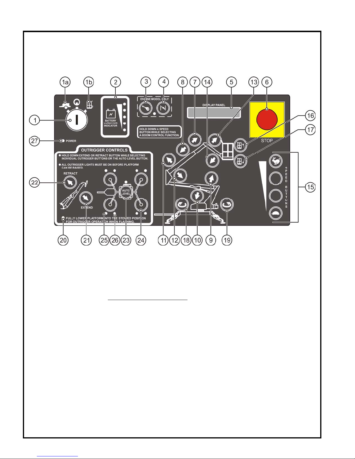
The ground (lower) control panel includes the following controls and indicators. Refer to Figure 3-1.
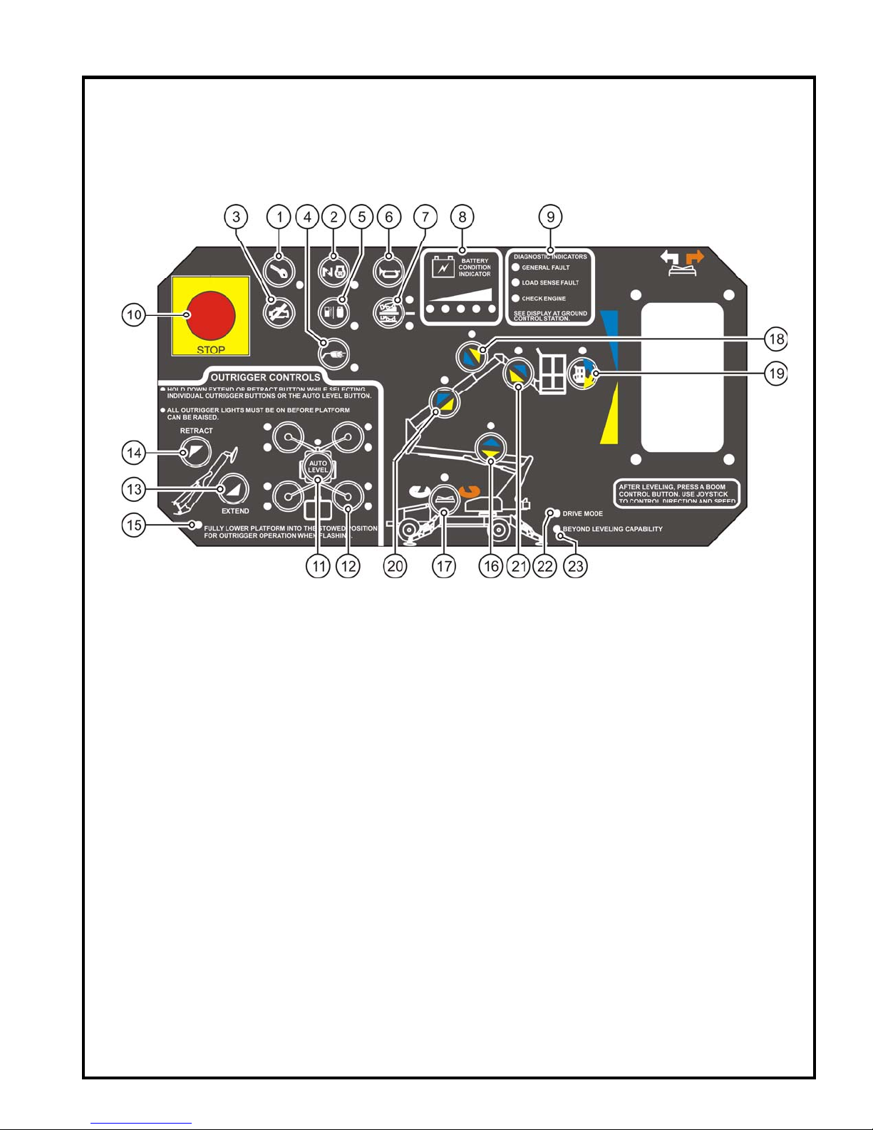
Figure 3-1. Ground (Lower) Control Panel
1. Key Switch
Turning the KEY SWITCH (1) counter clockwise to the GROUND (1a) icon selects operation
from the ground (lower) control panel. Turning the
PLATFORM
KEY SWITCH (1) to the vertical position (power “OFF”) interrupts all electric and hydraulic
power operations except emergency lowering
(1b) icon selects operation from the platform (upper) control panel. Turning the
. Removal of the KEY protects against any
KEY SWITCH (1), clockwise to the
unauthorized persons attempting to operate the aerial work platform. The
removed with the
KEY SWITCH (1) in any selected position.
2. Battery Condition Indicator
Indicator LEDs light up to indicate the level of charge in the batteries.
A lighted green LED indicates an adequate charge level.
A lighted yellow LED indicates the need for charging soon.
A lighted red LED warns that the battery charge level is low; all functional operations
become non-functional until the batteries are recharged.
3-4. Engine Start and Choke / Glow Plug
Start a cold engine by pressing (pushing) in and holding the CHOKE (4) button then press (push)
the
ENGINE START (3) button. To start / rest art a warm engine, press (push) the ENGINE START (3)
button only.
GLOW PLUG OPERATION – Press (push) the GLOW PLUG OPERATION (4) button and hold for 30-
60 seconds then press (push) the
ENGINE START (3) button.
KEY may be
22

HAULOTTE GROUP 3 OPERATION
GROUND (LOWER) CONTROL PANEL (CONTINUED)
5. Display Panel
The DISPL AY PANEL is a lighted text window that displays the current operating status or an
existing error condition when the
6. Emergency Stop Button
When pushed in, the EMERGENCY STOP (6) button disconnects electrical power to the ground
(lower) and platform (upper) control panels. The
pressed (pushed) in to immediately stop all aerial work platform motion. To resume control,
“pull out” the
EMERGENCY STOP (6).
7-8. Boom Extend / Retract Buttons
Pressing (pushing) in and holding a desired SPEED (15) button, and the BOOM EXTEND (7)
button at the same time extends the secondary boom. Pressing (pushing) in and holding a
desired
SPEED (15) button, and the BOOM RETRACT (8) button at the same time retracts the
secondary boom. Telescopic boom motion continues until the buttons are released, or until
the boom reaches a hard stop, or a safe travel limit.
9-14. Boom Raise / Down Buttons
Pressing (pushing) and holding a desired SPEED (15) button, and the PRIMARY BOOM
RAISE
(9) button at the same time will raise the primary boom. Pressing (pushing) and
holding a desired
same time will retract the primary boom.
Pressing (pushing) and holding a desired
RAISE (11) button at the same time will raise the secondary boom. Pressing (pushing)
and holding a desired
the same time will retract the secondary boom.
Pressing (pushing) and holding a desired
(13)
button at the same time will raise the JIB BOOM, pressing (pushing) and holding a
desired
retract the
SPEED (15) button, and the JIB BOOM DOWN (14) button at the same time will
JIB BOOM.
The selected Boom motion continues until the buttons are released or until the selected
boom reaches a hard stop or a safe travel limit
SPEED (15) button, and the PRIMARY BOOM DOWN (10) button at the
SPEED (15) button, and the SECONDARY BOOM DOWN (12) button at
KEY SWITCH (1) is positioned at either (1a) or (1b).
EMERGENCY STOP button should only be
SPEED (15) button, and the S ECONDARY BOOM
SPEED (15) button, and the JIB BOOM RAISE
.
15. Speed Buttons
The SPEED (15) buttons are located along the lower right side of the control panel, one of the
speed buttons must be pressed (pushed) in and held while selecting any boom function.
There are four speeds that range from fast (
control the positioning of the Boom and the Jib.
16-17. Platform Tilt Buttons
Press (push) and hold any SPEED (15) button, and the desired PLATFORM TILT UP (16) or
PLATFORM TILT DOWN (17) button at the same time to level the work platform. This levels the
platform only, NOT the aerial work platform.
18-19. Boom Rotation Buttons
Pressing (pushing) and holding a desired SPEED (15) button, and the BOOM ROTATION (18)
button at the same time enables the boom to rotate in the CLOCKWISE direction. Pressing
(pushing) and holding a desired
the same time enables the boom to rotate in the
will rotate through 700° of Non-Continuous rotation until the buttons are released or the stop
is reached.
RABBIT), to slow (TURTLE), available to help
SPEED (15) button, and the BOOM ROTATION (19) button at
COUNTER CLOCKWISE direction. The boom
23
HAULOTTE GROUP 3 OPERATION
GROUND (LOWER) CONTROL PANEL (CONTINUED)
Figure 3-1. Ground (Lower) Control Panel
20. Auto Level LED
When this LED is “FLASHING” it indicates that the booms are not in the “stowed” position,
and the outriggers are not functional. When this LED is “ON SOLID” it indicates that the
booms are in the “stowed” position, and the outriggers are functional.
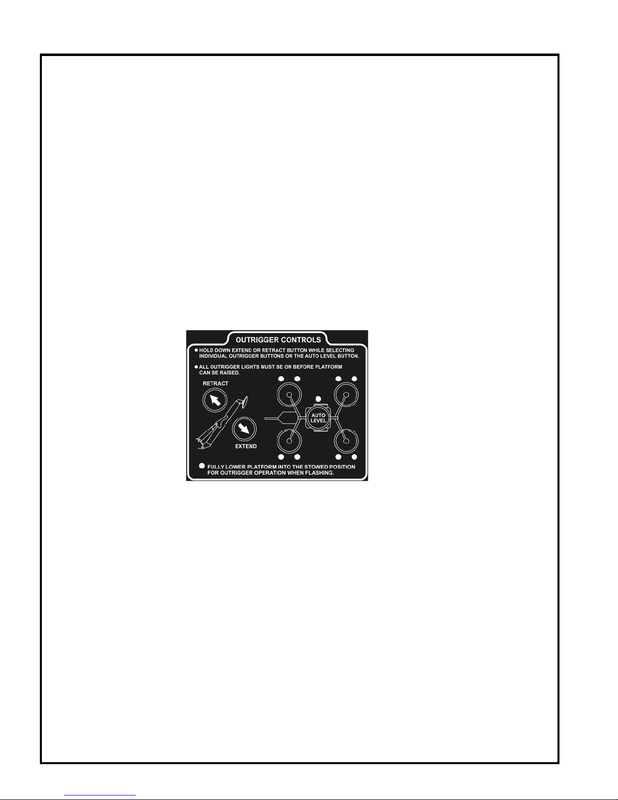
21-24. Outrigger Controls
For simultaneous automatic outrigger extension / retraction of all four (4) outriggers: Select
the
EXTEND (21) button or RETRACT (22) button and the AUTO LEVEL (23) button at the same
time. To individually extend or retract the outriggers: Select the
RETRACT
outrigger indicator LEDs (20) lights up when the outriggers are properly deployed and the
aerial work platform weight is on the outrigger foot pads. Each of the outer outrigger LEDs
(25) indicates load is on the outrigger foot pad. Each of the inner outrigger LEDs (26), when
flashing, indicate that side is low, and needs to be further raised for leveling.
(22) button, and one of the four OUTRIGGER (24) buttons at the same time. The
EXTEND (21) button or
24
HAULOTTE GROUP 3 OPERATION
PLATFORM (UPPER) CONTROL PANEL
The platform (upper) control panel is used to control all functions. The platform (upper) control panel
is activated by turning the
PLATFORM (1b) icon. Enter the work platform using a three (3) point contact (both hands and one foot).
The platform (upper) control panel includes the following controls and indicators. Refer to Figure 3-2.
KEY SWITCH (1) on the ground (lower) control panel, clockwise to the
Figure 3-2. Platform (Upper) Control Panel
1-2. Engine Start and Choke / Glow Plug
Start a cold engine by pressing (pushing) and holding the CHOKE (2) button and pressing
(pushing) the
press (push) the
GLOW PLUG OPERATION – Press (push) and hold the GLOW PLUG (2) button for 30-60 seconds
then press (push) the
ENGINE START (1) button to start the Engine. To start / restart a warm Engine,
START (1) button only.
ENGINE START (1) button.
3. Engine Stop
Press (push) the ENGINE STOP (3) button to shut the engine “OFF”.
4. Generator On / Off
To activate and / or deactivate the generator, press (push) the GENERATOR ON / OFF (4) button. When
the generator is “
ON” the LED will be lit. The generator provides power to the battery charger as well as
both GFI outlets (one on the wall of the turntable, one on the bulkhead).
5. Fuel Toggle
Press (push) the
FUEL TOGGLE (5) button to change between the different types of fuel.
6. Horn Button
Pressing (pushing) the HORN (6) button will sound the HORN. Use the HORN (6) button to warn
personnel in the area of a falling object hazard, impending boom motions, or the need for
assistance.
7.
Drive Speed Selector
Press (push) the
and high speed / low torque. The Low speed / high torque setting is the machines’ default
setting, and is recommended when operating on inclines.
DRIVE SPEED SELECTOR (7) button to switch between low speed / high torque
25
HAULOTTE GROUP 3 OPERATION
PLATFORM (UPPER) CONTROL PANEL (CONTINUED)
Figure 3-2. Pl atform (Upp er) Cont rol Panel
8. Battery Condition Indicator
Indicator LEDs light up to indicate the level of charge in the batteries.
A lighted green LED indicates an adequate charge level.
A lighted yellow LED indicates the need for charging soon.
A lighted red LED warns that the battery charge level is low; all functional operations
become non-functional until the batteries are recharged.
9. Diagnostic Indicators
Indicator LED’s warn of machine or engine issues.
9A. General Fault - When lit, refer to the
for an error code.
Refer to Table 4-3 Error Code Definitions, located in the “Equipment Maintenance”
section of this manual.
9B. Load Sense Fault - When lit, this is an indication of too much weight in the work
platform; all functional operations become non-functional until the weight is below the
Maximum Allowable Capacity (500 lb (227kg)) rating.
9C. Check Engine – When lit, turn the engine “
refer to the
DISPLAY PANEL on the ground (lower) control panel for an error code.
Refer to Table 4-3 Error Code Definitions, located in the “Equipment Maintenance”
section of this manual.
DISPLAY PANEL on the ground (lower) control panel
OFF” by using the ENGINE STOP (5) button;
10. Emergency Stop Button
When pushed in, the EMERGENCY STOP (10) button disconnects electrical power to the ground
(lower) and platform (upper) control panels. The
pressed (pushed) to immediately stop all aerial work platform functions. To resume control,
pull the
EMERGENCY STOP (10) button out.
11-15 Outrigger Controls
The Outrigger controls on the platform (upper) control panel are identical to the controls on the
ground (lower) control panel. Refer to the previous section for details.
26
EMERGENCY STOP (10) button should only be

HAULOTTE GROUP 3 OPERATION
PLATFORM (UPPER) CONTROL PANEL (CONTINUED)
NOTE: For all Boom Raising and Lowering, Extending and Retracting functions: Boom motion
continues until the
reached. When referencing moving the
operator, backwards is towards the operator.
16. Primary Boom Raise / Boom Lower Button
Press (push) the PRIMARY BOOM RAISE / BOOM LOWER (16) button until the LED is lit. Pressing
(squeezing) the
direction arrows, move the
the primary boom, move the
section
17. Boom Rotation Button
Press (push) the BOOM ROTATION (17) button until the LED is lit. To rotate CLOCKWISE press
and hold the right side (orange arrow) of the
COUNTER CLOCKWISE press and hold the left side (white arrow) of the TOGGLE button on top of
the
JOYSTICK. To rotate the boom, press (squeeze) the ENABLE LEVER on the JOYSTICK and
move the joystick slightly off center. The boom will rotate through 700° of Non-Continuous
rotation until the
18. Boom Extend / Retract Buttons
Press (push) the BOOM EXTEND / RETRACT (18) button until the LED is lit. Pressing (squeezing)
the
ENABLE LEVER on the JOYSTICK, enables the function. Using the color-coded direction
arrows, move the
secondary boom, move the
JOYSTICK is released, or until the boom reaches a hard stop or a safe travel limit is
JOYSTICK forward or backwards, forward is away from the
ENABLE LEVER on the JOYSTICK, enables the function. Using the color-coded
JOYSTICK slightly off center; move the JOYSTICK forward to raise
JOYSTICK backwards to lower the boom. Refer to the next
JOYSTICK – PLATFORM (UPPER) CONTROL PANEL for a visual of the JOYSTICK.
TOGGLE button on top of the JOYSTICK. To rotate
JOYSTICK is released, or a hard stop is reached.
JOYSTICK slightly off center; move the JOYSTICK back to extend the
JOYSTICK forward to retract the secondary boom.
19. Platform Tilt Button
Press (push) the PLATFORM TILT (19) button until the LED is lit. Pressing (squeezing) the
ENABLE LEVER on the JOYSTICK, enables the function. Using the color-coded direction arrows
move the
the
JOYSTICK backwards to lower the platform.
JOYSTICK slightly off center; move the JOYSTICK forward to ra ise the platform, move
This levels the platform only, NOT the aerial work platform.
20. Secondary Boom Raise / Boom Lower Button
Press (push) the SECONDARY BOOM RAISE / BOOM LOWER (20) button until the LED is lit.
Pressing (squeezing) the
color-coded direction arrows, move the
forward to raise the secondary boom, move the
ENABLE LEVER on the JOYSTICK, enables the function. Using the
JOYSTICK slightly off center; move the JOYSTICK
JOYSTICK backwards to lower the boom.
21. Jib Boom Raise / Boom Lower Button
Press (push) the JIB BOOM RAISE / BOOM LOWER (21) button until the LED is lit. Pressing
(squeezing) the
direction arrows, move the
the jib boom, move the
ENABLE LEVER on the JOYSTICK, enables the function. Using the color-coded
JOYSTICK slightly off center; move the JOYSTICK forward to raise
JOYSTICK backwards to lower the boom.
22. Drive Enable LED
Once the outriggers are retracted and in the “stowed” (upright) position, the aerial work
platform defaults to the
drivable. If the LED is not lit, check the control panel to see if there are any boom function
LED’s lit, if so toggle it off to enable the drive mode.
DRIVE MODE, the DRIVE MODE LED (22) will be lit, and the machine is
23. Beyond Leveling Capability
When the BEYOND LEVELING CAPABILITY LED (23) is lit; it is an indication that the aerial work
platform is on a grade that is beyond the machines leveling capability. The LED will stay lit
until the aerial work platform has reached a location that is within the machines leveling
capability.
27
HAULOTTE GROUP 3 OPERATION
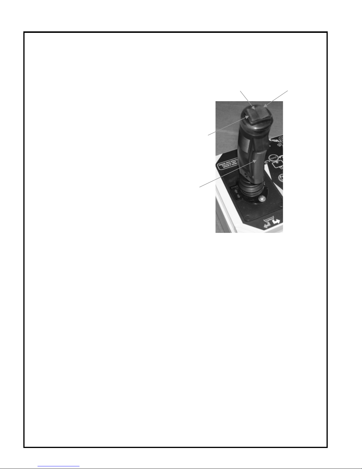
JOYSTICK - PLATFORM (UPPER) CONTROL PANEL
The platform (upper) control panel includes a JOYSTICK that operates the drive and boom functions
when the
Refer to Figure 3-3.
JOYSTICK TOGGLE SWITCH
The TOGGLE SWITCH is used in conjunction with
two separate functions; boom rotation, and
steering while driving the aerial work platform.
JOYSTICK ENABLE LEVER
To activate a function, press (push) the desired
function
(squeezing) the
enables the function. Using the color-coded
direction arrows move the
the neutral position, and in the desired direction.
Moving the
position increases the function speed. Boom
motion continues until:
The
The
The boom reaches a hard stop or a safe
Boom Rotation
ENABLE LEVER is pressed (squeezed).
button until the LED is lit, pressing
ENABLE LEVER on the JOYSTICK
JOYSTICK slightly off of
JOYSTICK away from the neutral
JOYSTICK is released.
JOYSTICK is returned to center.
travel limit.
TOGGLE
SWITCH
LEFT
TOGGLE
RIGHT
TOGGLE
ENABLE
LEVER
Figure 3-3. Platform Controls Joystick
Shown upside down and reversed for clarity.
Use the TOGGLE SWITCH to determine the direction of rotation. To rotate CLOCKWISE press the right
side of the
To rotate the boom: press (squeeze) the
TOGGLE SWITCH, to rotate COUNTER CLOCKWISE press the left side of the TOGGLE SWITCH.
ENABLE LEVER, using the TOGGLE SWITCH, select (press) a
direction, then move the joystick in either direction.
NOTE: When rotating the turntable, the turntable will rotate in the desired direction regardless of the
direction of the
JOYSTICK.
Driving the aerial work platform
TOGGLE SWITCH on the JOYSTICK is used to steer the machine.
The
To drive the aerial work platform, grasp the
the
JOYSTICK slightly off of the neutral position and in the direction of travel desired.
To turn / steer the aerial work platform either right or left, press (squeeze) the
press the desired
TOGGLE SWITCH on top of the JOYSTICK.
JOYSTICK and press (squeeze) the ENABLE LEVER, move
ENABLE LEVER and
28
HAULOTTE GROUP 3 OPERATION
NORMAL OPERATING PROCEDURE
Become familiar with the location and function of all controls. Learn to smoothly START and STOP all
boom functions.
Perform the following procedures to operate the machine:
Read and obey all safety precautions and operating instructions, as well as all Federal, State, and
Local codes and regulations.
Conduct a Pre-Operation Inspection by performing all recommended Daily Service Checks.
Refer to the “Equipment Maintenance” Section of this manual.
Position the aerial work platform at the work area. Make sure the aerial work platform is on a firm
and level surface and there are no potential hazards such as overhead obstructions or electrically
charged conductors. DO NOT operate the aerial work platform if such hazards exist.
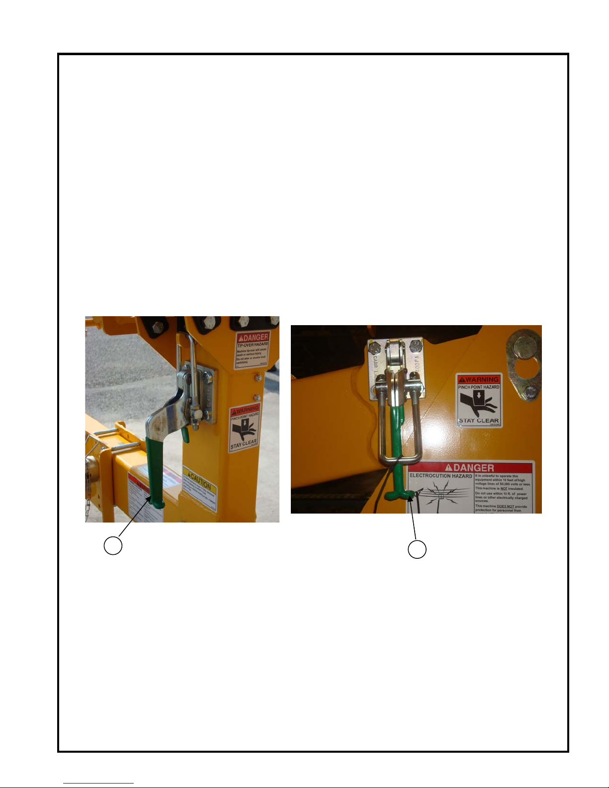
Release both travel latches, (1) the primary latch on the boom rest, and (2) the secondary latch
on the Primary Boom, by raising the latch handle and swinging the clasp down.
Refer to Figure 3-4.
PRIMARY
1
LATCH
Figure 3-4. Boom Travel Latches
SECONDARY
2
LATCH
29
HAULOTTE GROUP 3 OPERATION
NORMAL OPERATING PROCEDURE (CONTINUED)
Become familiar with the location and function of all controls. Learn to smoothly START and STOP all
boom functions.
At the ground (lower) control panel, turn the KEY SWITCH (1) counter clockwise to the GROUND
CONTROLS
buttons;
plugged in.
The control microprocessor will perform self-diagnostics to test the operating system. After
several seconds, the
Monitor the battery condition indicator during operation and charge the batteries as necessary.
(1a) icon. If power does not come on, make sure that both of the EMERGENCY STOP
GROUND (6), and PLATFORM (5), are pulled out and the main power disconnect plug is
DISPLAY PANEL window will read:
HAULOTTE GROUP
ACCESS SOLUTIONS
Extend the four outriggers individually, or for simultaneous extension use the
AUTO LEVEL (23)
button on the ground (lower) control panel. When the aerial work platform is leveled properly, a
buzzer will sound, the two LEDs at each
LEVEL
(23) button will be lit. Refer to Figure 3-5.
OUTRIGGER (25 and 26) button, and the LED at the AUTO
Figure 3-5. Outrigger Control Panel
o Auto Level: Press (push) and hold the
EXTEND (21) and AUTO LEVEL (23) buttons at the same
time.
o Manual Level: Extend the two outriggers closest to the trailer coupler first. Lower the front
pair of outriggers by pressing (pushing) the
EXTEND (21) button and the two front OUTRIGGER
buttons at the same time. Lower the back pair of outriggers by pressing (pushing) the
(21) button and the two back OUTRIGGER buttons at the same time.
EXTEND
Verify that the
AUTO LEVEL (23) indicator LED is lit. If the AUTO LEVEL (23) indicator is not lit, the
aerial work platform may not be level, and the weight of the machine may not be on the outrigger
foot pad.
NOTE: If the boom is not level or if one or more outriggers are not supporting the
machines load the safety interlock system prevents all boom operations.
NOTE: The Range of Motion Diagrams at the ground (lower) and platform (upper) control
stations displays the range of platform motion (safe operating zone). Verify that the
operating zone is clear of obstructions through 700º of Non-Continuous rotation.
30
 Loading...