


Operator's manual
3522A - HTA13P - 4527A - HTA16P - 5533A - HTA19P
Operator's manual
3522A - HTA13P - 4527A - HTA16P - 5533A
- HTA19P
3522A - HTA13P - 4527A - HTA16P -
5533A - HTA19P
24203 0
X
USA
4000670470 E 04.19 USA / GB

3522A - HTA13P - 4527A - HTA16P - 5533A - HTA19P
2 4000670470 E 04.19 USA / GB

Operator's manual
CONTENTS
A
FOREWORD
1 - User responsibility . . . . . . . . . . . . . . . . . . . . . . .
1.1 - Owner's responsibility. . . . . . . . . . . . . . . . . . . . . . . . . . . . . . . . . . . . . . . . . . . 8
1.2 - Employer's responsibility . . . . . . . . . . . . . . . . . . . . . . . . . . . . . . . . . . . . . . . . 8
1.3 - Trainer's responsibility. . . . . . . . . . . . . . . . . . . . . . . . . . . . . . . . . . . . . . . . . . . 8
1.4 - Operator's responsibility. . . . . . . . . . . . . . . . . . . . . . . . . . . . . . . . . . . . . . . . . 9
2 - Safety. . . . . . . . . . . . . . . . . . . . . . . . . . . . . . . . .
2.1 - Safety instructions . . . . . . . . . . . . . . . . . . . . . . . . . . . . . . . . . . . . . . . . . . . . . 10
2.1.1 - Misuse Hazards . . . . . . . . . . . . . . . . . . . . . . . . . . . . . . . . . . . . . 10
2.1.2 - Falling Hazards . . . . . . . . . . . . . . . . . . . . . . . . . . . . . . . . . . . . . 11
2.1.3 - Overturning / Tip-over Hazards . . . . . . . . . . . . . . . . . . . . . . . . . 12
2.1.4 - Electrocution Hazards . . . . . . . . . . . . . . . . . . . . . . . . . . . . . . . . 14
2.1.5 - Explosion / Fire Hazards . . . . . . . . . . . . . . . . . . . . . . . . . . . . . . 15
2.1.6 - Crushing / Collision Hazards . . . . . . . . . . . . . . . . . . . . . . . . . . . 15
2.1.7 - Uncontrolled movement Hazards . . . . . . . . . . . . . . . . . . . . . . . . 16
3 - Safety inquiries. . . . . . . . . . . . . . . . . . . . . . . . .
4 - Incident notification . . . . . . . . . . . . . . . . . . . . .
5 - Compliance . . . . . . . . . . . . . . . . . . . . . . . . . . . .
5.1 - Product information. . . . . . . . . . . . . . . . . . . . . . . . . . . . . . . . . . . . . . . . . . . . 18
5.1.1 - Change of Ownership Notification . . . . . . . . . . . . . . . . . . . . . . . 18
5.1.2 - Owner information update form . . . . . . . . . . . . . . . . . . . . . . . . . 19
5.2 - Product specifications. . . . . . . . . . . . . . . . . . . . . . . . . . . . . . . . . . . . . . . . . . 20
8
10
17
17
18
B
FAMILIARIZATION
1 - General safety. . . . . . . . . . . . . . . . . . . . . . . . . .
1.1 - Intended use. . . . . . . . . . . . . . . . . . . . . . . . . . . . . . . . . . . . . . . . . . . . . . . . . . 21
1.2 - Decal content . . . . . . . . . . . . . . . . . . . . . . . . . . . . . . . . . . . . . . . . . . . . . . . . . 22
1.3 - Symbols and colors . . . . . . . . . . . . . . . . . . . . . . . . . . . . . . . . . . . . . . . . . . . 23
1.4 - Level of severity . . . . . . . . . . . . . . . . . . . . . . . . . . . . . . . . . . . . . . . . . . . . . . . 23
1.5 - Symbols legend and definitions . . . . . . . . . . . . . . . . . . . . . . . . . . . . . . . . . 24
2 - Models description. . . . . . . . . . . . . . . . . . . . . .
3 - Primary machine components . . . . . . . . . . . .
3.1 - Layout. . . . . . . . . . . . . . . . . . . . . . . . . . . . . . . . . . . . . . . . . . . . . . . . . . . . . . . . 26
CONTENTS
3.2 - Ground control box . . . . . . . . . . . . . . . . . . . . . . . . . . . . . . . . . . . . . . . . . . . . 28
3.2.1 - Layout . . . . . . . . . . . . . . . . . . . . . . . . . . . . . . . . . . . . . . . . . . . . 28
3.3 - Platform control box . . . . . . . . . . . . . . . . . . . . . . . . . . . . . . . . . . . . . . . . . . . 32
3.3.1 - Layout . . . . . . . . . . . . . . . . . . . . . . . . . . . . . . . . . . . . . . . . . . . . 32
4 - Performance Specifications . . . . . . . . . . . . . .
4.1 - Technical characteristics . . . . . . . . . . . . . . . . . . . . . . . . . . . . . . . . . . . . . . . 36
4.2 - Working area / Range of motion . . . . . . . . . . . . . . . . . . . . . . . . . . . . . . . . 42
5 - Decals and markings locations. . . . . . . . . . . .
21
25
26
36
45
3

Operator's manual
C
PRE-OPERATION INSPECTION
1 - Recommendations . . . . . . . . . . . . . . . . . . . . . .
2 - Working area assessment . . . . . . . . . . . . . . . .
3 - Inspection and Functional test . . . . . . . . . . . .
3.1 - Daily inspection . . . . . . . . . . . . . . . . . . . . . . . . . . . . . . . . . . . . . . . . . . . . . . . 73
3.2 - Inspection Form. . . . . . . . . . . . . . . . . . . . . . . . . . . . . . . . . . . . . . . . . . . . . . . 77
4 - Safety functional checks . . . . . . . . . . . . . . . . .
4.1 - E-Stop button check . . . . . . . . . . . . . . . . . . . . . . . . . . . . . . . . . . . . . . . . . . . 79
4.2 - Activation of controls . . . . . . . . . . . . . . . . . . . . . . . . . . . . . . . . . . . . . . . . . . . 80
4.3 - Fault detector . . . . . . . . . . . . . . . . . . . . . . . . . . . . . . . . . . . . . . . . . . . . . . . . . 80
4.3.1 - Indicators/LED's test . . . . . . . . . . . . . . . . . . . . . . . . . . . . . . . . . 80
4.4 - Automatic engine cut-out. . . . . . . . . . . . . . . . . . . . . . . . . . . . . . . . . . . . . . . 81
4.5 - Outriggers . . . . . . . . . . . . . . . . . . . . . . . . . . . . . . . . . . . . . . . . . . . . . . . . . . . . 81
D
71
72
73
79
OPERATION INSTRUCTIONS
1 - Operation. . . . . . . . . . . . . . . . . . . . . . . . . . . . . .
1.1 - Introduction . . . . . . . . . . . . . . . . . . . . . . . . . . . . . . . . . . . . . . . . . . . . . . . . . . . 83
1.2 - Operation from the ground control box. . . . . . . . . . . . . . . . . . . . . . . . . . . 85
1.3 - Operation from the platform control box. . . . . . . . . . . . . . . . . . . . . . . . . . 86
2 - Ground control box . . . . . . . . . . . . . . . . . . . . .
2.1 - Boom and arm controls . . . . . . . . . . . . . . . . . . . . . . . . . . . . . . . . . . . . . . . . 87
3 - Platform control box . . . . . . . . . . . . . . . . . . . .
3.1 - To start and stop the machine . . . . . . . . . . . . . . . . . . . . . . . . . . . . . . . . . . 89
3.2 - Platform box controls (Primary station). . . . . . . . . . . . . . . . . . . . . . . . . . . 90
3.3 - Additional controls . . . . . . . . . . . . . . . . . . . . . . . . . . . . . . . . . . . . . . . . . . . . . 91
4 - Outriggers extension . . . . . . . . . . . . . . . . . . . .
5 - Rescue and emergency procedures. . . . . . . .
5.1 - In case of power loss . . . . . . . . . . . . . . . . . . . . . . . . . . . . . . . . . . . . . . . . . . 94
5.1.1 - Manual Boom Operation . . . . . . . . . . . . . . . . . . . . . . . . . . . . . . 95
5.1.1.1 - Manual retraction . . . . . . . . . . . . . . . . . . . . . . . . . . . . . . . . . . . . 95
5.1.1.2 - Manual rotation. . . . . . . . . . . . . . . . . . . . . . . . . . . . . . . . . . . . . . 95
5.1.1.3 - Manual Boom Lowering Procedure . . . . . . . . . . . . . . . . . . . . . . 96
5.2 - To rescue operator in platform . . . . . . . . . . . . . . . . . . . . . . . . . . . . . . . . . . 97
5.3 - No power available . . . . . . . . . . . . . . . . . . . . . . . . . . . . . . . . . . . . . . . . . . . . 97
83
87
89
92
94
4

Operator's manual
6 - Transportation . . . . . . . . . . . . . . . . . . . . . . . . .
6.1 - Putting in transport position . . . . . . . . . . . . . . . . . . . . . . . . . . . . . . . . . . . . . 98
6.1.1 - Machine layout . . . . . . . . . . . . . . . . . . . . . . . . . . . . . . . . . . . . . . 98
6.1.2 - Transporting on to a truck bed . . . . . . . . . . . . . . . . . . . . . . . . . . 99
6.1.3 - Unloading . . . . . . . . . . . . . . . . . . . . . . . . . . . . . . . . . . . . . . . . . . 99
6.2 - Towing. . . . . . . . . . . . . . . . . . . . . . . . . . . . . . . . . . . . . . . . . . . . . . . . . . . . . . 100
6.2.1 - Procedure to hitch and tow. . . . . . . . . . . . . . . . . . . . . . . . . . . . 101
6.3 - Storage . . . . . . . . . . . . . . . . . . . . . . . . . . . . . . . . . . . . . . . . . . . . . . . . . . . . . 102
6.4 - Lifting operation . . . . . . . . . . . . . . . . . . . . . . . . . . . . . . . . . . . . . . . . . . . . . . 103
7 - Cold Weather Recommendations . . . . . . . . .
7.1 - Engine oil. . . . . . . . . . . . . . . . . . . . . . . . . . . . . . . . . . . . . . . . . . . . . . . . . . . . 104
7.2 - Hydraulic oil. . . . . . . . . . . . . . . . . . . . . . . . . . . . . . . . . . . . . . . . . . . . . . . . . . 104
E
GENERAL SPECIFICATIONS
1 - Machine dimensions . . . . . . . . . . . . . . . . . . .
2 - Major component masses . . . . . . . . . . . . . . .
3 - Acoustics and vibrations. . . . . . . . . . . . . . . .
4 - Wheel/Tire assembly . . . . . . . . . . . . . . . . . . .
4.1 - Technical specifications . . . . . . . . . . . . . . . . . . . . . . . . . . . . . . . . . . . . . . . 109
4.2 - Inspection and maintenance. . . . . . . . . . . . . . . . . . . . . . . . . . . . . . . . . . . 110
5 - Options . . . . . . . . . . . . . . . . . . . . . . . . . . . . . .
5.1 - Important . . . . . . . . . . . . . . . . . . . . . . . . . . . . . . . . . . . . . . . . . . . . . . . . . . . . 114
5.2 - Drive and set. . . . . . . . . . . . . . . . . . . . . . . . . . . . . . . . . . . . . . . . . . . . . . . . . 115
5.2.1 - Drive and set safety . . . . . . . . . . . . . . . . . . . . . . . . . . . . . . . . . 115
5.2.2 - Drive and set controls. . . . . . . . . . . . . . . . . . . . . . . . . . . . . . . . 116
5.2.3 - Drive and set use . . . . . . . . . . . . . . . . . . . . . . . . . . . . . . . . . . . 118
5.2.3.1 - Initial Operation . . . . . . . . . . . . . . . . . . . . . . . . . . . . . . . . . . . . 118
5.2.3.2 - During Operation . . . . . . . . . . . . . . . . . . . . . . . . . . . . . . . . . . . 119
5.3 - Platform rotator. . . . . . . . . . . . . . . . . . . . . . . . . . . . . . . . . . . . . . . . . . . . . . . 120
98
104
106
108
108
109
114
CONTENTS
5

Operator's manual
F
MAINTENANCE
1 - General . . . . . . . . . . . . . . . . . . . . . . . . . . . . . .
2 - Maintenance Schedule. . . . . . . . . . . . . . . . . .
3 - Inspection program . . . . . . . . . . . . . . . . . . . .
3.1 - General program. . . . . . . . . . . . . . . . . . . . . . . . . . . . . . . . . . . . . . . . . . . . . 123
3.2 - Daily inspection . . . . . . . . . . . . . . . . . . . . . . . . . . . . . . . . . . . . . . . . . . . . . . 123
3.3 - Periodic inspection. . . . . . . . . . . . . . . . . . . . . . . . . . . . . . . . . . . . . . . . . . . . 124
3.4 - Reinforced inspection. . . . . . . . . . . . . . . . . . . . . . . . . . . . . . . . . . . . . . . . . 124
3.5 - Major inspection. . . . . . . . . . . . . . . . . . . . . . . . . . . . . . . . . . . . . . . . . . . . . . 124
4 - Repairs and adjustments. . . . . . . . . . . . . . . .
G
OTHER INFORMATION
1 - HAULOTTE® new product warranty
North America . . . . . . . . . . . . . . . . . . . . . . . . . . .
1.1 - Warranty claims procedure. . . . . . . . . . . . . . . . . . . . . . . . . . . . . . . . . . . . 129
1.2 - Warranty registration. . . . . . . . . . . . . . . . . . . . . . . . . . . . . . . . . . . . . . . . . . 130
2 - Subsidiary contact information. . . . . . . . . . .
2.1 - California warning . . . . . . . . . . . . . . . . . . . . . . . . . . . . . . . . . . . . . . . . . . . . 132
121
122
123
125
127
131
6

A
B
C
D
E
F
G
H
I
3522A - HTA13P - 4527A - HTA16P - 5533A - HTA19P
A
- Foreword
You have just purchased a HAULOTTE® product and we would like to thank you for your business.
Foreword
The Aerial Work Platform is a mechanical device primarily designed and manufactured with the intent to position people
with the necessary tools and material to overhead elevated temporary workplaces. All other uses or alterations/
modifications to the aerial work platform must be approved by HAULOTTE®.
This equipment is designed and manufactured in compliance with the duties, responsiblities and standards set forth for
manufacturers in the ANSI, CSA and AS standards in effect at the time of manufacture.
This equipment meets or exceeds applicable ANSI and CSA standards when operated in accordance with
manufacturer's recommendations.
This manual shall be considered a permanent component of the machine and shall be kept with the aerial work platform
in the designated Manual Holder, at all times.
Safe operation of this product can only be assured if you follow the operating instructions contained in this manual. To
ensure proper and safe use of this equipment, only trained and authorized personnel must operate and maintain the
aerial work platform.
We would particularly like to draw your attention to 2 essential points :
• Comply with safety instructions.
• Use the equipment within the specified/published performance limits.
With regard to the designation of our equipment, we stress that this is purely for commercial purposes and not to be
confused with the technical specifications. Only the specifications in this manual should be used to study the suitability
of the equipment for the intended use.
This operator's manual is specific to the HAULOTTE® products listed on the cover page of this manual.
Original language and version :
Manuals in English and French are the original instructions. Manuals in other languages are translations
of the original instructions.
The operator's manual does not replace the basic training required for equipment operators. HAULOTTE® has compiled
this manual to assist in safe and efficient operation of the products covered in the manual.
The manual must be available to all operators and must be kept in a legible condition. Additional copies can be ordered
from HAULOTTE Services®.
Stay Safe and keep working with HAULOTTE® !
7 4000670470 E 04.19 USA / GB

3522A - HTA13P - 4527A - HTA16P - 5533A - HTA19P
A
- Foreword
1 - User responsibility
1.1 - OWNER'S RESPONSIBILITY
The owner (or hirer) has the obligation :
• To inform operators of the instructions contained in the Operator's Manual.
• For applying the local regulations regarding operation of the machine.
• To replace all manuals or decals that are either missing or not legible. Additional copies can
be ordered from HAULOTTE Services®.
• To establish a preventive maintenance program in accordance with the manufacturer's
recommendations, taking into account the environment and severity of use of the machine.
• To perform periodic inspections in accordance with HAULOTTE® recommendations and
local regulations.
All malfunctions and problems identified during the inspection shall be corrected before the
aerial work platform is returned to service.
1.2 - EMPLOYER'S RESPONSIBILITY
The employer has the obligation :
• To authorize the operator to use the machine.
• To inform and familiarize the operator with the local regulations.
Forbid anyone from operating the machine if :
• Under the influence of drugs, alcohol, etc.
• Subject to fits, loss of motor skills, dizziness, etc.
1.3 - TRAINER'S RESPONSIBILITY
The trainer must be qualified to provide training to operators in accordance with applicable
local regulations. The training must be given in an obstacle-free area until the trainee is
considered competent as defined by the training program undertaken.
8 4000670470 E 04.19 USA / GB

A
B
C
D
E
F
G
H
I
3522A - HTA13P - 4527A - HTA16P - 5533A - HTA19P
A
- Foreword
1.4 - OPERATOR'S RESPONSIBILITY
The operator has the obligation to :
• Read and understand the contents of this manual and familiarize himself with the decals
affixed on the machine.
• To inspect the machine before use according to HAULOTTE®'s recommendations..
• Inform the owner (or hirer) if the manual or any decals are missing or are not legible.
• To inform of any malfunctioning of the machine.
The operator shall ensure that frequent inspections were conducted by the owners and the
operator may only operate the machine for the purpose intended by the manufacturer.
Only authorized and qualified operators may operate HAULOTTE® machines.
All operators must become familiar with and fully understand the emergency controls and be
able to operate the machine in an emergency.
The operator has the obligation to stop using the machine in the event of malfunction or safety
problems on the machine or in the work area and report the problem immediately to his/her
supervisor.
9 4000670470 E 04.19 USA / GB

3522A - HTA13P - 4527A - HTA16P - 5533A - HTA19P
A
- Foreword
2 - Safety
2.1 - SAFETY INSTRUCTIONS
2.1.1 - Misuse Hazards
• Do not use the machine for any other purpose than to position
people, their tools and material to the overhead/elevated
temporary work places.
• Do not use the machine as a crane, material lift or elevator.
Only use the machine as it was intended.
• Do not attach overhanging loads when raising or lowering the platform.
• Do not tie the boom or platform to an adjacent fixed or mobile structure.
• Do not use/operate the machine when alone. A survey person or immediate Supervisor must
be present on the ground in case of emergency.
• Do not use a faulty or poorly maintained machine. Remove defective/damaged machine
from service.
• Do not climb onto the compartment covers of the machine.
• Do not replace items critical to machine stability with items of different weight or specification.
• Do not replace factory-installed tires with tires of different specifications or ply rating.
• Do not alter or disable machine components that in any way affect safety and stability.
• Do not disable the safety devices.
• Do not deface, modify or obscure any decals or markings on the aerial work platform.
10 4000670470 E 04.19 USA / GB
A
B
C
D
E
F
G
H
I
3522A - HTA13P - 4527A - HTA16P - 5533A - HTA19P
307P216290 b
x 1
A
- Foreword
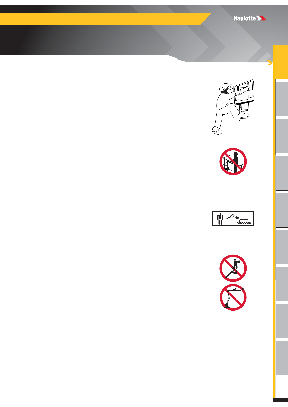
2.1.2 - Falling Hazards
To enter or exit from the platform :
• The machine must be completely stowed.
• Face the machine to access the entry opening to the platform.
• Keep 3 points of contact (both hands and a foot) on the steps
and the guardrail.
Before commencing operation :
• Ensure that guard rails are correctly installed and secured.
• Ensure that gate or sliding bar is in it’s proper closed position.
• Remove oil or grease from the steps, floor, handrail and the
guardrails.
• Clear the platform floor free of debris.
When in the platform :
• Occupants must wear a fall arrest harness with energy
absorber, in accordance with applicable governmental
regulations. Attach the lanyard to the designated fall arrest
anchor provided in the platform.
• The correct use of the harness requires the lanyard to be
connected to an anchorage point designated by the decals.
Refer to this decal located on the platform.
• Hold on securely to the guardrails.
• Always keep your feet firmly on the floor of the platform.
• Do not sit, stand, or climb on the platform guard rails.
• Work only within the platform guardrails area and do not lean
over guardrails to perform work.
• Do not exit the platform until it is in the completely stowed
position.
• Do not use the guardrail as a means of access to climb in or
out of the platform.
11 4000670470 E 04.19 USA / GB
3522A - HTA13P - 4527A - HTA16P - 5533A - HTA19P
A
- Foreword
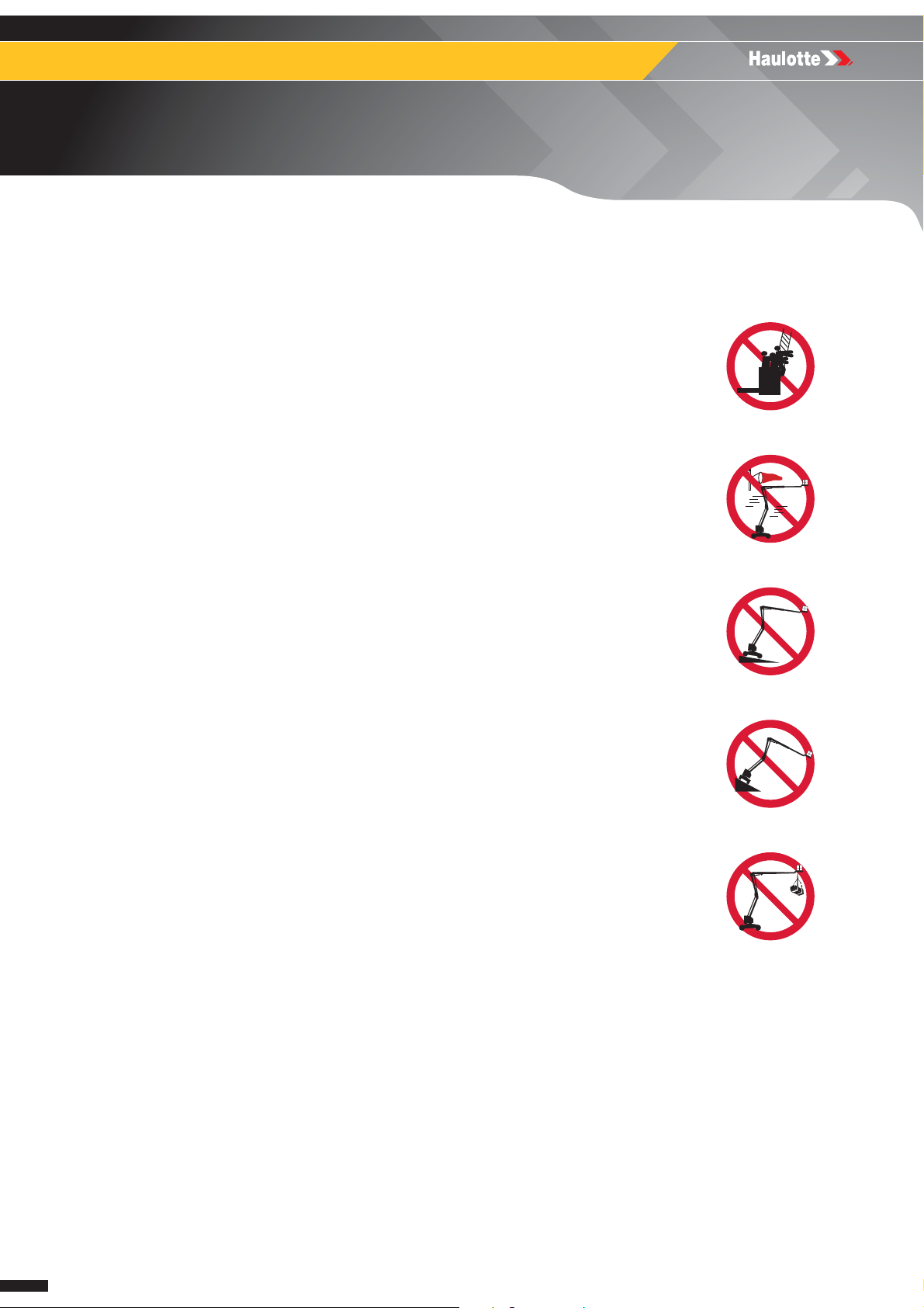
2.1.3 - Overturning / Tip-over Hazards
Before positioning and operating the machine :
• Ensure that the surface is capable of supporting the machine weight
including the rated capacity. Check the load bearing capacity of the
supporting ground.
• Do not operate on surfaces that do not support force exerted by the
outriggers during aerial work platform operation.
• Do not exceed the maximum rated capacity that includes the weight
of both material and allowed number of occupants. Do not exceed
the allowable number of occupants.
• Place the loads uniformly distributed on the platform floor.
• Do not increase the working height (using extensions, ladder, etc.).
• Do not place ladders or scaffolds in the platform or against any part
of this machine.
• Do not use the machine in winds exceeding the permissible limit.
• Do not increase the surface area of the platform exposed to wind.
This includes adding panels, mesh, banners. Be aware when
working with materials with a large surface area. This will add to the
wind load on the machine.
• Do not replace components critical to stability with components of
different weight or specification.
• Do not use the machine with material or objects hanging from the
guardrail or the boom.
• Do not pull or push towards any object outside of the platform. Do not
exceed the maximum allowable side force stated in the performance
specifications.
• Do not use boom or platform to push or pull or to lift any part of the
trailer.
• Do not use the machine to support any external structure.
• Do not use the machine to drag materials.
• Do not operate aerial work platform without outriggers fully extended
or when platform is not level.
• Do not raise the outriggers or move the trailer with materials or
personnel on board, or while boom is raised or extended.
12 4000670470 E 04.19 USA / GB

A
B
C
D
E
F
G
H
I
3522A - HTA13P - 4527A - HTA16P - 5533A - HTA19P
A
- Foreword
WIND : The aerial work platform can operate up to a maximum wind speed as indicated in the
specifications. To identify the local wind speed, use the Beaufort scale below, use a wind
gauge or an anemometer.
N.B.-:-T
COMMUNICATING
CLEAR LAND IS ASSOCIATED WITH EACH DEGREE.
Force
0 Calm Smoke rises vertically. 0 - 0,3 0 - 1 1
1 Very light breeze Smoke indicates the wind direction. 0,3 - 1,5 1 - 5 1 - 3
2 Light breeze
3 Slight breeze
4 Nice breeze
5 Nice breeze
6 Cool wind
7 Near gale
8 Gale
9 Strong gale
10
Storm, Violent Storm,
Hurricane
HE BEAUFORT SCALE OF WIND FORCE IS ACCEPTED INTERNATIONALLY AND IS USED WHEN
WEATHER CONDITIONS. A WIND SPEED RANGE AT 10 M (32 FT 9 IN) ABOVE FLAT,
Beaufort scale
Meteorological
description
Wind felt on the face. Leaves rustle.
Weather vanes turn.
Leaves and small twigs in constant
motion. Flags move slightly.
Raised dust and loose papers. Small
branches are moved.
Small trees in leaf to sway. Crested
wavelets form on inland waterways.
Large branches in motion. Power
lines and chimneys 'sing'. Umbrellas
used with difficulty.
Whole trees in motion. Inconvenience
felt when walking against wind.
Some branches break. Generally we
cannot walk against the wind.
The wind causes slight damage to
buildings. Tiles and chimney stacks
are blown off.
Trees uprooted, widespread damage
to structures, widespread
devastation.
Observed effects m/s km/h mph
1,6 - 3,3 6 - 11 4 - 7
3,4 - 5,4 12 - 19 8 - 12
5,5 - 7,9 20 - 28 13 - 17
8,0 - 10,7 29 - 38 18 - 24
10,8 - 13,8 39 - 49 25 - 30
13,9 - 17,1 50 - 61 31 - 38
17,2 - 20,7 62 - 74 39 - 46
20,8 - 24,4 75 - 88 47 - 54
More
than 24,5
More
than 89
More
than 55
13 4000670470 E 04.19 USA / GB
3522A - HTA13P - 4527A - HTA16P - 5533A - HTA19P
A
- Foreword
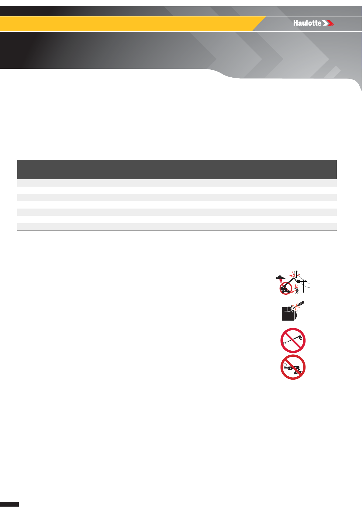
2.1.4 - Electrocution Hazards
The machine is not electrically insulated and does not provide protection from contact or
proximity to electrically charged conductors.
Always position the lift at a safe distance from electrically charged conductors to ensure that
no part of the machine is within an unsafe area.
Respect the local rules and the minimum safety distance from power lines.
Minimum safe approach distances
Electric voltage Minimum safety distance
Mètre Feet
0 - 300 V Avoid contact
300 V - 50 kV 3 10
50 - 200 kV 5 15
200 - 350 kV 6 20
350 - 500 kV 8 25
500 - 750 kV 11 35
750 - 1000 kV 14 45
N.B.-:-U
• Do not operate the machine when close to live power lines,
consider the movement of the machine and the sway of the
electric power lines particularly in windy conditions.
• Do not operate the machine during lightning, thunderstorms,
snow/ice or any weather condition that could compromise
operator safety.
• Do not use the machine as a ground for welding.
• Do not weld on the machine without first disconnecting the
battery terminals.
• Always disconnect ground cable first.
• The machine must not be used while charging the batteries.
• When using the AC power supply, ensure it is protected with a
circuit breaker and residual current device.
Keep away from the machine if it contacts energized power
lines. Personnel on the ground or in the platform must not touch
or operate the machine until energized power lines are shut off.
SE THIS TABLE EXCEPT WHERE LOCAL REGULATIONS INDICATE OTHERWISE.
14 4000670470 E 04.19 USA / GB
A
B
C
D
E
F
G
H
I
3522A - HTA13P - 4527A - HTA16P - 5533A - HTA19P
A
- Foreword
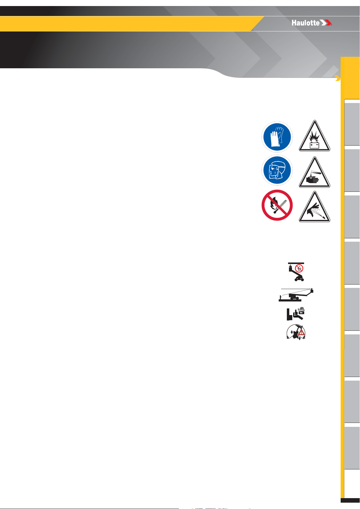
2.1.5 - Explosion / Fire Hazards
Always wear protective clothing and eye wear when working with
batteries and power sources/systems.
N.B.-:-A
• Do not start the engine if you smell or detect liquid propane gas
(LPG), gasoline, diesel fuel or other explosive substances.
• Do not work on or operate a machine in an explosive or flammable
atmosphere / environment.
• Do not touch hot components.
• Do not bridge the battery terminals with metallic objects.
• Do not service the battery in proximity of spark, open flame, lit
cigarettes.
• Do not fill up the fuel tank, when the engine is running and/or near
a flame.
• Avoid contact with battery acid. Battery acid causes serious burns
and should be kept away from skin or eyes. If contact occurs, flush
with water and consult a physician immediately.
2.1.6 - Crushing / Collision Hazards
CID IS NEUTRALIZED WITH SODIUM BICARBONATE AND WATER.
When in the platform :
• Check the work area for clearance overhead, beside and below
the platform when lifting and lowering the platform.
• During movement, keep all the parts of the body inside the
platform. Hold onto the guardrails on the opposite side to any
surrounding structures. Take care to avoid trapping hands whilst
holding the guardrails.
• Ensure there are no obstacles (structure) in the work area.
• Always cordon off the area around the base of the machine to keep personnel and other
equipment away from the machine while in use.
• Warn personnel not to work, stand, or walk under a raised boom/platform.
• Do not drive in reverse direction (opposite the field of vision).
• Be aware of the boom position and tail swing when rotating the turret (turntable).
• Always ensure that the chassis is never driven any closer than 1 m (3 ft 3 in) to holes,
bumps, slopes, obstructions, debris and ground coverings that may hide holes and other
dangers.
• Keep non-operating personnel at least 5 m (16 ft 5 in) away from the machine when driving
and slewing.
15 4000670470 E 04.19 USA / GB

3522A - HTA13P - 4527A - HTA16P - 5533A - HTA19P
A
- Foreword
• Be aware of driving direction.
• When changing the driving direction (Forward <> Reverse) the joysticks or switches must return to the neutral
position before reversing the drive direction and for movement to occur.
• When driving, position the platform so as to provide the best possible visibility and to avoid
any blind spots.
• Hold on securely to the guardrails.
• Occupants must wear a fall arrest harness with energy absorber, in accordance with
applicable governmental regulations. Attach the lanyard to the designated fall arrest anchor
provided in the platform.
• Avoid contact with fixed or mobile obstacles (other machines).
• Other machines (crane, aerial work platform, etc.) operating in the work area increase the
risk of crushing or collision. Restrict the operation of machines moving within the aerial work
platform work area.
• Take into consideration the stopping distance, reduced visibility and blind spots of the
machine.
• Limit travel speed to suit the ground surface condition, slope (incline), and people in the
vicinity.
2.1.7 - Uncontrolled movement Hazards
Do not use a damaged or malfunctioning machine.
Be aware of uncontrolled movement and always respect the following :
• Maintain clearance from high voltage lines.
• Maintain clearance from generators, radar, electromagnetic fields.
• Never expose the batteries or electrical components to water (high pressure washer, rain).
• Never tow the machine over extended distances.
• In case of a machine breakdown, it is possible to tow short distance to load it onto a trailer.
• Never leave the hydraulic cylinders fully extended before switching off the machine, or when
stationary for an extended period of time.
• Retract the boom and lower the arms to the stowed position.
• Select a safe parking location, on a firm level surface, clear of obstruction and traffic.
• Ensure all compartments are closed and secured.
• Chock the wheels.
• Do not leave keys in the aerial work platform while unattended or not in use.
16 4000670470 E 04.19 USA / GB

A
B
C
D
E
F
G
H
I
3522A - HTA13P - 4527A - HTA16P - 5533A - HTA19P
A
- Foreword
3 - Safety inquiries
Inquiries relating to design criteria/specifications of a product, standards compliance, or overall
machine safety should be sent to the HAULOTTE® PRODUCT SAFETY department.
Each inquiry or request should include all relevant information; including contact name, telephone
number, mailing address, email address, plus the machine model and serial number.
The HAULOTTE® Product Safety department will evaluate each request/inquiry and will provide a
written response.
4 - Incident notification
Notify HAULOTTE® immediately when a HAULOTTE® product has been involved in an incident/
accident leading to personal injury or death, or when there is a major property damage.
HAULOTTE Group - EUROPE
Product Safety Department
Address : La Péronnière - BP 9 42152 L'Horme - France
Tel : +33 (0)4 77 29 24 24
HAULOTTE Group - Australia, India and
Asia Product Safety Department
Address : No.26 Changi North Way Singapore 498812 - Singapore
Tel : +65 6546 0123
HAULOTTE Group - North & South
America Product Safety Department
Address : 3409 Chandler Creek Rd. Virginia Beach, VA 23453 - United States
Tel : +1 757 689 2146
Email : ProductSafety@haulotte.com
Email : ProductSafety@haulotte.com
Email : ProductSafety@haulotte.com
17 4000670470 E 04.19 USA / GB

3522A - HTA13P - 4527A - HTA16P - 5533A - HTA19P
A
- Foreword
5 - Compliance
5.1 - PRODUCT INFORMATION
Without the written permission from Haulotte, modifying a HAULOTTE® product is a Safety
concern. Any modification may violate Haulotte design parameters, government regulations
and industry standards.
If you desire a modification to the product, submit a request in writing to HAULOTTE®.
With the utmost care to ensure enhanced reliability and greater safety of the HAULOTTE®
products, it is pertinent that when a "Service or Safety Bulletin" is issued, action is taken
immediately. Once the bulletin has been addressed, make sure that the completed form is
submitted to HAULOTTE®.
Do not hesitate to contact HAULOTTE Services®, should you have any questions relating to
the issued bulletin(s) or with questions on the policy itself.
5.1.1 - Change of Ownership Notification
It is important and necessary to keep HAULOTTE Services® updated with current ownership
of the machine. This way, HAULOTTE® will be able to provide the necessary support for the
product. If you have sold or transferred this machine(s); it is your responsibility to
notify HAULOTTE Services®. It is not required to include Lessees/Renters of Leased/Rented
machines on this form.
Use the HAULOTTE® Product Status Notification form to report scrapped, stolen, missing or
recovered machine(s).
18 4000670470 E 04.19 USA / GB

A
B
C
D
E
F
G
H
I
3522A - HTA13P - 4527A - HTA16P - 5533A - HTA19P
A
- Foreword
5.1.2 - Owner information update form
Owner information update form
Complete this form and mail or fax it to :
HAULOTTE® subsidiary Name : Address 1 :
Fax : Address 2 :
e.mail address : Address 3 :
Product information :
Model : Machine serial number :
Owner / Servicing information :
Do not include leased or rented units in this form
Current product owner 1 : Current product owner 2 :
Name : Name :
Company : Company :
Address 1 : Address 1 :
Address 2 : Address 2 :
Country : Country :
Phone : Phone :
Date of ownership : Date of ownership :
Signature : Signature :
Date : Date :
Company stamp is mandatory : Company stamp is mandatory :
Check here if the machine has been permanently removed from service (scrapped). The manufacturer's
nameplate must be removed and returned to HAULOTTE Group when the unit is removed from service.
Reason for removal :
19 4000670470 E 04.19 USA / GB

3522A - HTA13P - 4527A - HTA16P - 5533A - HTA19P
A
- Foreword
5.2 - PRODUCT SPECIFICATIONS
HAULOTTE® cannot be held liable for any changes to the technical characteristics/
specifications contained in this manual. HAULOTTE® has a continuous improvement policy
in place for its product range. Given this policy, the Company reserves the right to modify
products technical characteristics / specifications without notice.
Certain options/accessories can modify the machine's operating characteristics and its'
associated safety. If your machine was originally delivered with options fitted, replacing a
safety component associated with a particular option does not require any particular
precaution other than those associated with the installation itself (static test).
Otherwise, it is essential to follow the manufacturer's recommendations as stated below :
• Installation by authorised HAULOTTE® personnel only.
• Update the manufacturer's identification plate.
• Have stability tests carried out by a certified agency/competent person.
• Ensure decals are updated.
20 4000670470 E 04.19 USA / GB

A
B
C
D
E
F
G
H
I
3522A - HTA13P - 4527A - HTA16P - 5533A - HTA19P
B
- Familiarization
Familiarization
1 - General safety
1.1 - INTENDED USE
Do not operate the product in the following situations :
• On soft, unstable or cluttered ground.
• With wind blowing faster than the permissible limit.
• Check the allowable wind speed specified in the performace specifications tabulation.
• Consult the Beaufort scale.
• Close to power lines. Keep a safe distance.
• If the machine is stored at a temperature out of range - 20°C / + 50°C (- 4°F / + 122°F).
• In an explosive atmosphere / environment.
• During storms.
• In the presence of strong electromagnetic fields.
N.B.-:-U
MACHINE
TEMPERATURES, SALINITY, CORROSIVENESS, ATMOSPHERIC PRESSURE), CONTACT HAULOTTE
ERVICES®. REDUCE INTERVALS BETWEEN SERVICING.
S
SE THE MACHINE UNDER "NORMAL" CLIMATIC CONDITIONS. IF YOU NEED TO USE THE
IN CLIMATIC CONDITIONS LIKELY TO CAUSE DETERIORATION (EXTREME : HUMIDITY,
N.B.-:-W
FULLY
CONTROL
HILE THE MACHINE IS NOT IN USE, CARE MUST BE TAKEN TO BRING THE MACHINE TO THE
STOWED POSITION. ENSURE THAT THE MACHINE IS LOCKED IN A SECURE LOCATION, AND THE
KEY IS REMOVED TO PREVENT UNAUTHORISED USE OF THE MACHINE.
21 4000670470 E 04.19 USA / GB
3522A - HTA13P - 4527A - HTA16P - 5533A - HTA19P
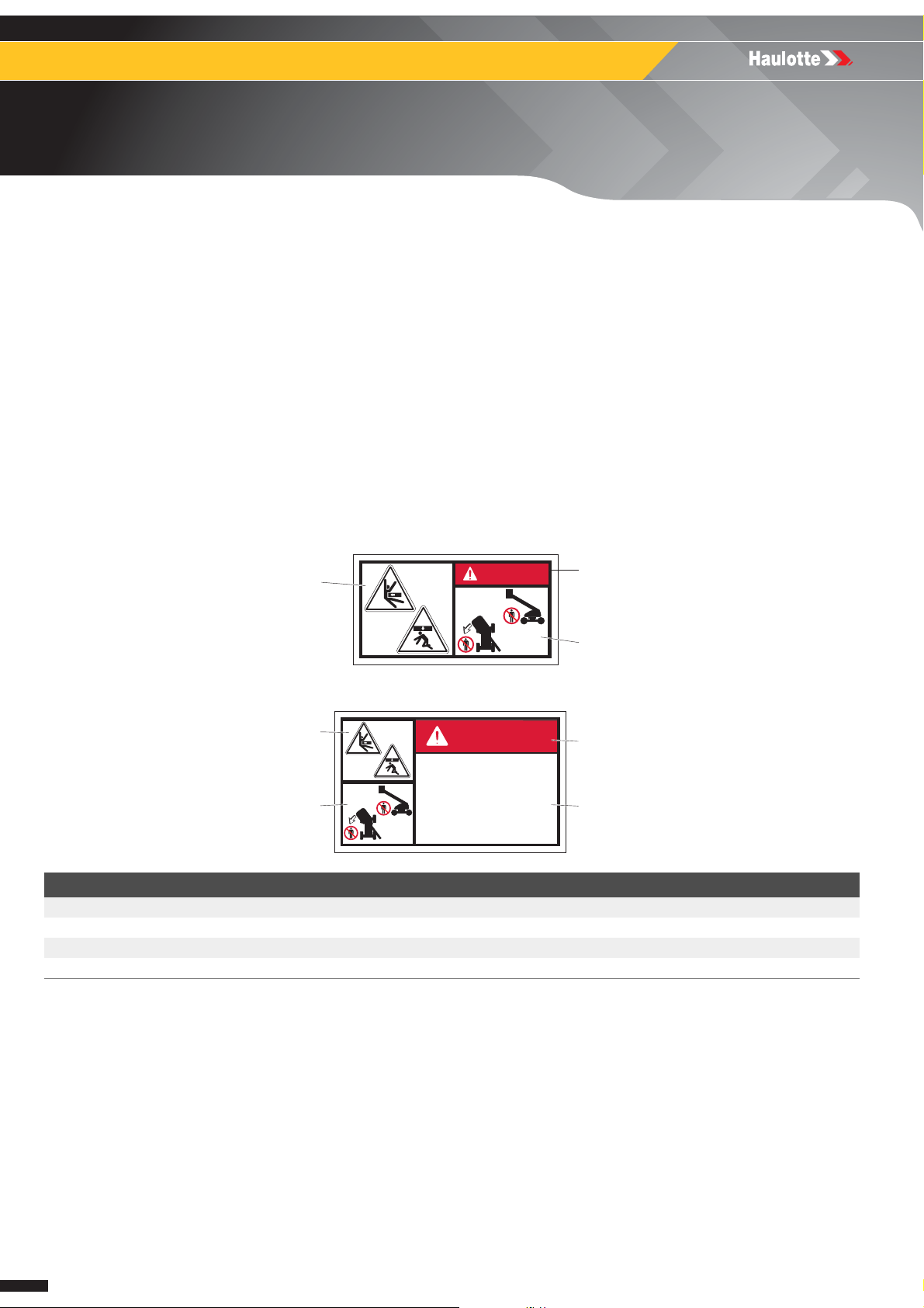
DANGER
CRUSH HAZARD
Do not stand or walk behind or in front
of the machine while in use.
Stay clear from the path of boom
rotation and platform lowering.
Failure to comply will result in death
or in serious injury
1
3
2
4
B
- Familiarization
1.2 - DECAL CONTENT
Decals are provided to alert the user of hazards inherent with the Aerial Work Platforms.
Decals provide the following information :
• The level of severity.
• The specific hazard.
• A method to avoid, suppress or reduce the hazard.
• Descriptive text (where required).
Familiarize yourself with the decals and the hazard severity levels.
Decals must be kept in good legible condition.
Familiarize yourself with the decals and their respective color codes.
Additional decals can be ordered from HAULOTTE Services®.
AS standard
1
DANGER
ANSI and CSA standards
Marking Description
1 Hazard symbol
2 Level of severity
3 Avoidance symbol pictorial
4 Avoidance text
2
3
22 4000670470 E 04.19 USA / GB
A
B
C
D
E
F
G
H
I
3522A - HTA13P - 4527A - HTA16P - 5533A - HTA19P
B
- Familiarization
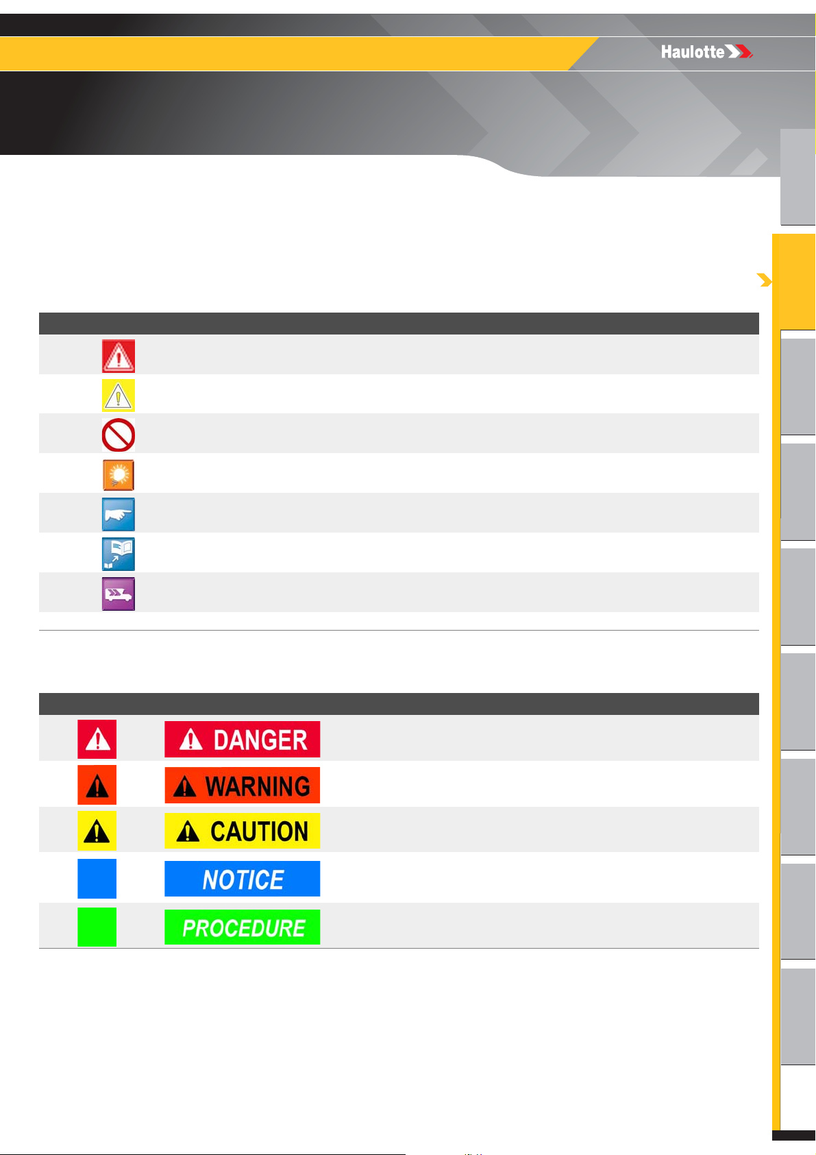
1.3 - SYMBOLS AND COLORS
Symbols and colors are used to alert the operator of safety precautions and/or to highlight
important safety information.
The following safety symbols are used throughout this manual to indicate specific hazards and
the hazard severity level when operating or maintaining the Aerial Work Platform.
Symbol Description
Danger : Risk of injury or death
Caution : Risk of material damage
Prohibited action
Reminder to use good practice or follow pre-operation checks
Cross-reference to another part of the manual
Cross-reference to another manual
Cross-reference to repair (contact HAULOTTE Services®)
N.B. : Additional technical information
1.4 - LEVEL OF SEVERITY
Color Title Description
Danger : Indicates a hazardous situation which if not avoided,
WILL result in death or serious injury.
Warning : Indicates a hazardous situation which if not avoided,
COULD result in death or serious injury.
Caution : Failure to comply could result in minor or moderate
injury.
Notice : Indicates recommended practices if not followed, may
result in a malfunction or damage the machine or its
components.
Procedure : Indicates a maintenance operation.
23 4000670470 E 04.19 USA / GB
3522A - HTA13P - 4527A - HTA16P - 5533A - HTA19P
x 1
B
- Familiarization
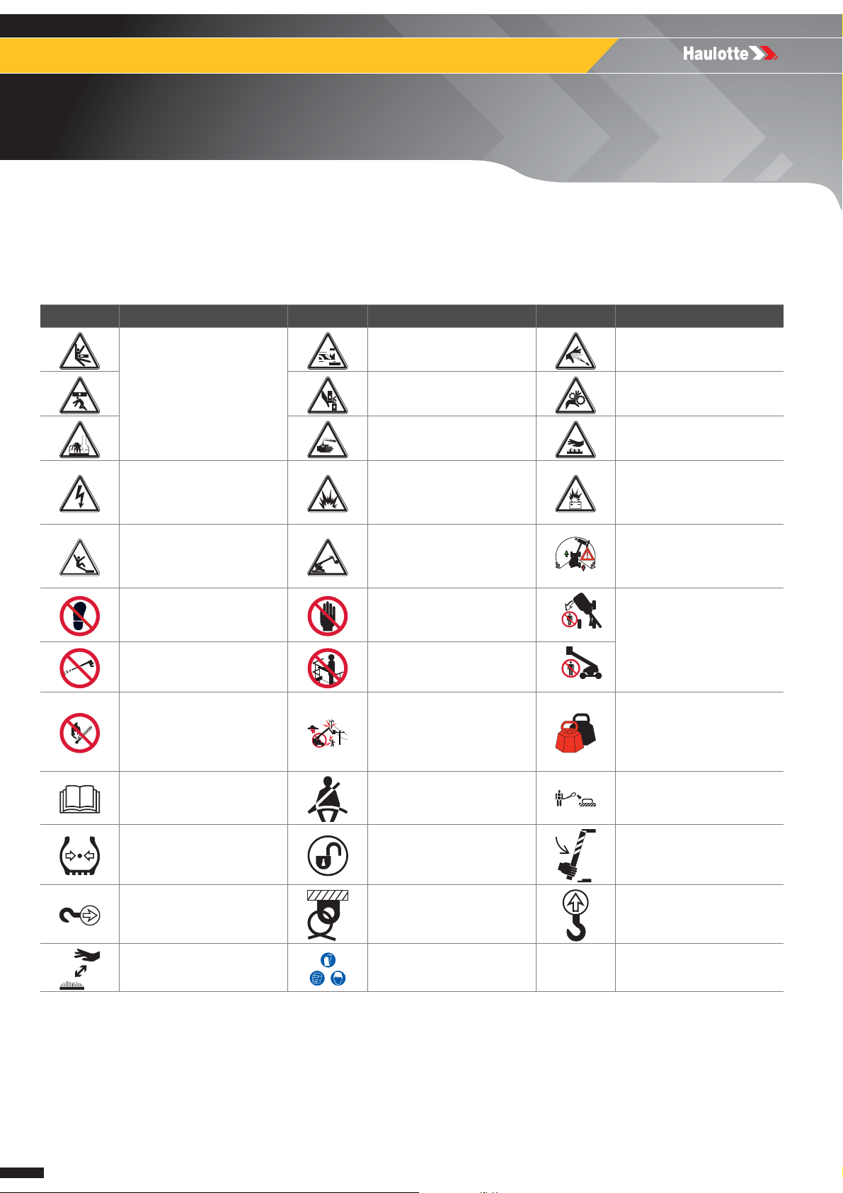
1.5 - SYMBOLS LEGEND AND DEFINITIONS
Symbols are used throughout this manual to depict hazards, avoidance measures and indicate
when information is required.
Refer to the following table to familiarize yourself with these symbols.
Symbol Description Symbol Description Symbol Description
Foot crushing hazard
Body crushing hazard
Electrical contact or lightning
strike
Risk of operator(s) falling
Do not put foot in this area
Never expose batteries and
electrical component to high
pressure washer
Flames prohibited
Refer to operator manual Safety belt
Hand crushing hazard Entanglement hazard
Health/safety hazards
related to chemicals
Burns and scalds from
contact with flames,
explosion or radiation from
heat sources
Tip over due to excessive
loading / wind load and
excessive ground slope
Do not put your hand in this
area
Ensure entry drop rail is
down
Maintain safe clearance from
high voltage electrically
charged conductors as
described in manual - Do not
use in thunderstorms
High pressure fluid ejection
hazard
Health-damaging effects
from hot work environment
Injury from Electric arcs Energy supply disconnecting
devices - Batteries fire,
emissions, etc
Relate and coordinate
directional arrows on the
chassis with those on the
control box
Keep away from product
working area
Overload
Use appropriate lanyard
attached to dedicated
anchor point.
Use safety prop before
Wheel pressure Enable switch
Tow point Tie down point Lift point
Keep away from hot surfaces Wear protective equipment
24 4000670470 E 04.19 USA / GB
attempting any maintenance
work

A
B
C
D
E
F
G
H
I
3522A - HTA13P - 4527A - HTA16P - 5533A - HTA19P
B
- Familiarization
2 - Models description
Regulations Models
ANSI and CSA standards
AS standard
3522A
4527A
5533A
HTA13P
HTA16P
HTA19P
25 4000670470 E 04.19 USA / GB
3522A - HTA13P - 4527A - HTA16P - 5533A - HTA19P
B
- Familiarization
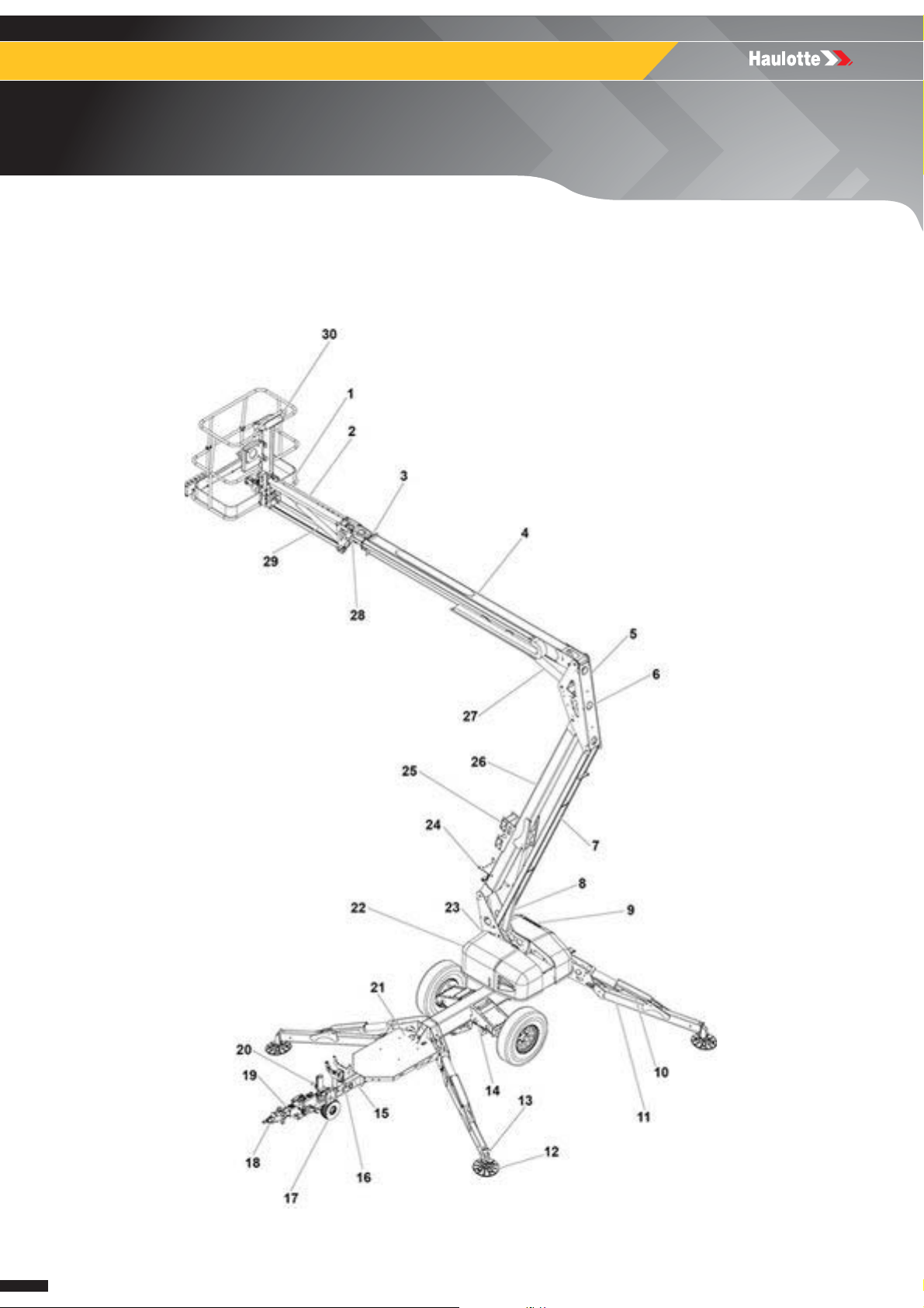
3 - Primary machine components
3.1 - LAYOUT
3522A - HTA13P - 4527A - HTA16P - 5533A - HTA19P
26 4000670470 E 04.19 USA / GB

A
B
C
D
E
F
G
H
I
3522A - HTA13P - 4527A - HTA16P - 5533A - HTA19P
B
- Familiarization
Marking Description Marking Description
C1 Platform C16 Latch release
C2 Jib boom C17 Dolly wheel
C3 Extension boom C18 Trailer hitch
C4 Secondary boom C19 Coupler
C5 Knuckle C20 Jack
C6 Master cylinder C21 Generator interface plate
C7 Lower link C22 Power unit compartment
C8 Primary lift cylinder C23 Turntable
C9 Ground control box C24 Secondary boom rest
C10 Outrigger cylinder C25 Forklift pocket
C11 Outrigger leg C26 Primary boom
C12 Outrigger pad C27 Secondary lift cylinder
C13 Outrigger foot C28 Slave cylinder
C14 Axle C29 Jib lift cylinder
C15 Primary boom rest C30 Platform control box
27 4000670470 E 04.19 USA / GB
3522A - HTA13P - 4527A - HTA16P - 5533A - HTA19P
B
- Familiarization
3.2 - GROUND CONTROL BOX
3.2.1 - Layout
General view
28 4000670470 E 04.19 USA / GB

A
B
C
D
E
F
G
H
I
3522A - HTA13P - 4527A - HTA16P - 5533A - HTA19P
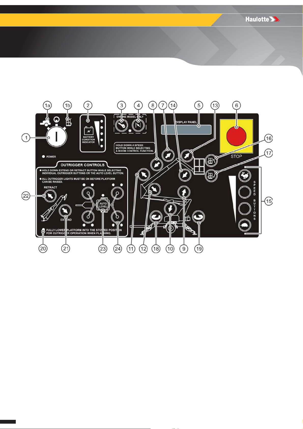
B
- Familiarization
Controls and indicators
Marking Description Function
• Turn the KEY SWITCH ( 1 ) to the GROUND ( 1a ) to select operation from the
ground control box.
• Turn the KEY SWITCH ( 1 ) to the PLATFORM ( 1b ) to select operation from
1 Key Switch
2 Battery Condition Indicator
3 - 4
5 Display panel
6 Emergency stop button
7 - 8
9 - 14
15 Speed/Enable buttons
Engine Start and Choke /
Glow Plug
Boom Extend / Retract
Buttons
Boom Raise / Down Buttons
and Jib Raise / Down
Buttons
1
the platform control box.
• Turn the KEY SWITCH ( 1 ) to the off position . Power supply is now
switched off.
• Remove the key to protect against unauthorized operation.
Indicator LEDs light up to indicate the level of charge in the batteries :
• A lighted green LED indicates an adequate charge level.
• A lighted yellow LED indicates the need for charging soon.
• A lighted red LED warns that the battery charge level is low; all functional
operations become non-functional until the batteries are recharged.
• Start a cold engine : Press and hold the CHOKE ( 4 ) then press the ENGINE
START ( 3 ). To start/restart a warm engine, press the ENGINE START ( 3 ).
• Press and hold the GLOW PLUG ( 4 ) for 30 - 60 seconds then press the
ENGINE START ( 3 ).
The DISPLAY PANEL is a lighted text window that displays the current operating
status or an existing error condition when the KEY SWITCH ( 1 ) is positioned at
either(1a) or(1b).
• When pushed in, the EMERGENCY STOP ( 6 ) button disconnects electrical
power to the ground (lower) and platform (upper) control boxes
• The EMERGENCY STOP button should only be pressed (pushed) in to
immediately stop all aerial work platform motion.
• To resume control, “pull out” the EMERGENCY STOP ( 6 ).
• Pressing (pushing) in and holding a desired SPEED/ENABLE ( 15 ) button,
and the BOOM EXTEND ( 7 ) button at the same time extends the secondary
boom.
• Pressing (pushing) in and holding a desired SPEED/ENABLE ( 15 ) button,
and the BOOM RETRACT ( 8 ) button at the same time retracts the secondary
boom.
• Telescopic boom motion continues until the buttons are released, or until the
boom reaches a hard stop, or a safe travel limit.
• Pressing (pushing) and holding a desired SPEED/ENABLE ( 15 ) button, and
the PRIMARY BOOM RAISE ( 9 ) button at the same time will raise the primary
boom. Pressing (pushing) and holding a desired SPEED/ENABLE ( 15 ) button,
and the PRIMARY BOOM DOWN ( 10 ) button at the same time will retract the
primary boom.
• Pressing (pushing) and holding a desired SPEED/ENABLE ( 15 ) button, and
the SECONDARY BOOM RAISE ( 11 ) button at the same time will raise the
secondary boom. Pressing (pushing) and holding a desired SPEED/
ENABLE ( 15 ) button, and the SECONDARY BOOM DOWN ( 12 ) button at the
same time will retract the secondary boom.
• Pressing (pushing) and holding a desired SPEED/ENABLE ( 15 ) button, and
the JIB BOOM RAISE ( 13 ) button at the same time will raise the JIB BOOM,
pressing (pushing) and holding a desired SPEED/ENABLE ( 15 ) button, and
the JIB BOOM DOWN ( 14 ) button at the same time will retract the JIB BOOM.
• The selected Boom motion continues until the buttons are released or until the
selected boom reaches a hard stop or a safe travel limit.
• The SPEED/ENABLE ( 15 ) buttons are located along the lower right side of
the control panel, one of the speed/enable buttons must be pressed (pushed) in
and held while selecting any boom function.
• There are four speeds that range from fast (RABBIT), to slow (TURTLE),
available to help control the positioning of the Boom and the Jib.
29 4000670470 E 04.19 USA / GB

3522A - HTA13P - 4527A - HTA16P - 5533A - HTA19P
B
- Familiarization
Marking Description Function
• Press (push) and hold any SPEED/ENABLE ( 15 ) button, and the desired
16 - 17 Platform Leveling Buttons
18 - 19 Turret Rotation Buttons
20 Booms stowed LED
21 - 26 Outrigger controls
27 Power • The LED ( 27 ) lights up when power is On.
1. For machines with engines only
PLATFORM TILT UP ( 16 ) or PLATFORM TILT DOWN ( 17 ) button at the
same time to level the work platform.
• This levels the platform only, NOT the aerial work platform.
• Pressing (pushing) and holding a desired SPEED ( 15 ) button, and the
TURRET ROTATION ( 18 ) button at the same time enables the turret to rotate
in the CLOCKWISE direction.
• Pressing (pushing) and holding a desired SPEED ( 15 ) button, and the
TURRET ROTATION ( 19 ) button at the same time enables the turret to rotate
in the COUNTER CLOCKWISE direction.
• The turret will rotate through 700° of Non-Continuous rotation until the buttons
are released or the stop is reached.
• When this LED is "FLASHING" it indicates that the booms are not in the
"stowed" position, and the outriggers cannot be operated (non-functional).
• When this LED is "ON SOLID" it indicates that the booms are in the "stowed"
position, and the outriggers can be operated (functional).
For simultaneous automatic outrigger extension / retraction of all four ( 4 )
outriggers :
• Select the EXTEND ( 21 ) button or RETRACT ( 22 ) button and the AUTO
LEVEL ( 23 ) button at the same time.
To individually extend or retract the outriggers :
• Select the EXTEND ( 21 ) button or RETRACT ( 22 ) button, and one of the
four OUTRIGGER ( 24 ) buttons at the same time.
• The outrigger indicator LEDs ( 20 ) and ( 23 ) light up when the outriggers are
properly deployed and the aerial work platform weight is on the outrigger foot
pads.
• Each of the outer outrigger LEDs ( 25 ) indicates load is on the outrigger foot
pad.
• Each of the inner outrigger LEDs ( 26 ), when flashing, indicate that side is
low, and needs to be further raised for leveling.
30 4000670470 E 04.19 USA / GB

A
B
C
D
E
F
G
H
I
3522A - HTA13P - 4527A - HTA16P - 5533A - HTA19P
B
- Familiarization
Notes
31 4000670470 E 04.19 USA / GB

3522A - HTA13P - 4527A - HTA16P - 5533A - HTA19P
B
- Familiarization
3.3 - PLATFORM CONTROL BOX
3.3.1 - Layout
General view
32 4000670470 E 04.19 USA / GB

A
B
C
D
E
F
G
H
I
3522A - HTA13P - 4527A - HTA16P - 5533A - HTA19P
B
- Familiarization
Controls and indicators
Marking Description Function
• Start a cold engine by pressing (pushing) in and holding the CHOKE ( 2 ) button
1-2
3 Horn button
4
5 Emergency stop button
6 Speed/Enable buttons
7-8 Boom Rotation Buttons
9-14
Engine Start and Choke /
Glow Plug
Battery Condition
Indicator
Boom Raise / Down
Buttons and Jib Raise /
Down Buttons
1
then press (push) the ENGINE START ( 1 ) button. To start / restart a warm engine,
press (push) the ENGINE START ( 1 ) button only.
• Glow plug operation : Press (push) the GLOW PLUG ( 2 ) button and hold for 30 60 seconds then press (push) the ENGINE START ( 1 ) button
Pressing (pushing) the HORN button ( 3 ) will sound the HORN.
Use the horn button to warn personnel in the area of a falling object hazard,
impending boom motions or the need for assistance.
Indicator LEDs light up to indicate the level of charge in the batteries :
• A lighted green LED indicates an adequate charge level.
• A lighted yellow LED indicates the need for charging soon.
• A lighted red LED warns that the battery charge level is low; all functional
operations become non-functional until the batteries are recharged.
• When pushed in, the EMERGENCY STOP ( 5 ) button disconnects electrical
power to the ground (lower) and platform (upper) control boxes
• The EMERGENCY STOP button ( 5 ) should only be pressed (pushed) to
immediately stop all boom functions.
• To resume control, “pull out” the EMERGENCY STOP ( 5 ).
• The SPEED/ENABLE ( 6 ) buttons are located along the lower right side of the
control panel, one of the speed/enable buttons must be pressed (pushed) in and
held while selecting any boom function.
• There are four speeds that range from fast (RABBIT), to slow (TURTLE), available
to help control the positioning of the Boom and the Jib.
• Pressing (pushing) and holding a desired SPEED/ENABLE ( 6 ) button, and the
BOOM ROTATION ( 7 ) button at the same time enables the boom to rotate in the
CLOCKWISE direction.
• Pressing (pushing) and holding a desired SPEED/ENABLE ( 6 ) button, and the
BOOM ROTATION ( 8 ) button at the same time enables the boom to rotate in the
COUNTER CLOCKWISE direction.
• The boom will rotate through 700° of Non-Continuous rotation until the buttons
are released or the stop is reached.
• Pressing (pushing) and holding a desired SPEED/ENABLE ( 6 ) button, and the
PRIMARY BOOM RAISE ( 9 ) button at the same time will raise the primary boom.
Pressing (pushing) and holding a desired SPEED/ENABLE ( 6 ) button, and the
PRIMARY BOOM DOWN ( 10 ) button at the same time will retract the primary
boom.
• Pressing (pushing) and holding a desired SPEED/ENABLE ( 6 ) button, and the
SECONDARY BOOM RAISE ( 11 ) button at the same time will raise the secondary
boom. Pressing (pushing) and holding a desired SPEED/ENABLE ( 6 ) button, and
the SECONDARY BOOM DOWN ( 12 ) button at the same time will retract the
secondary boom.
• Pressing (pushing) and holding a desired SPEED/ENABLE ( 6 ) button, and the
JIB BOOM RAISE ( 13 ) button at the same time will raise the JIB BOOM, pressing
(pushing) and holding a desired SPEED/ENABLE ( 6 ) button, and the JIB BOOM
DOWN ( 14 ) button at the same time will retract the JIB BOOM.
• The selected Boom motion continues until the buttons are released or until the
selected boom reaches a hard stop or a safe travel limit.
33 4000670470 E 04.19 USA / GB

3522A - HTA13P - 4527A - HTA16P - 5533A - HTA19P
B
- Familiarization
Marking Description Function
• Pressing (pushing) in and holding a desired SPEED/ENABLE ( 6 ) button, and the
BOOM EXTEND ( 15 ) button at the same time extends the secondary boom.
15-16
17-18
1. For machines with engines only
Boom Extend / Retract
Buttons
Platform Leveling
Buttons
Outlet
• Pressing (pushing) in and holding a desired SPEED/ENABLE button, and the
BOOM RETRACT ( 16 ) button at the same time retracts the secondary boom.
• Telescopic boom motion continues until the buttons are released, or until the
boom reaches a hard stop, or a safe travel limit.
• Press (push) and hold any SPEED/ENABLE ( 6 ) button, and the desired
PLATFORM TILT UP ( 17 ) or PLATFORM TILT DOWN ( 18 ) button at the same
time to level the work platform.
• This levels the platform only, NOT the aerial work platform.
An outlet has been provided as a power source for running electrical power tools,
while in the work platform. The power plug is located on the trailer frame, in front of
the accessory equipment stowage plate. A connecting power cord must be plugged
into a suitable power source. The outlet is rated for a 15 A load. Do not overload
the accessory power circuit.
34 4000670470 E 04.19 USA / GB

A
B
C
D
E
F
G
H
I
3522A - HTA13P - 4527A - HTA16P - 5533A - HTA19P
B
- Familiarization
Notes
35 4000670470 E 04.19 USA / GB

3522A - HTA13P - 4527A - HTA16P - 5533A - HTA19P
B
- Familiarization
4 - Performance Specifications
4.1 - TECHNICAL CHARACTERISTICS
Use the table to select the right Haulotte machine for the job.
ANSI, CSA and AS standards
Machine 3522A - HTA13P
Characteristics - Dimensions SI Imp.
Maximum working height 12,9 m 41 ft 9 in
Maximum platform height 10,9 m 35 ft 9 in
Up and over height 5,8 m 19 ft 0 in
Maximum horizontal outreach :
• From centerline of rotation
• From outrigger footpad edge
Rated platform capacity :
• Without platform rotator option
• With platform rotator option
Maximum number of occupants 2
Maximum wind speed allowed 45 km/h 28 mph
Total weight :
• Without option
• Drive and set option adds 113 kg (250 lb), Engine option adds 86 kg (190
lb), all other options add 68 kg (150 lb) to weight
Turntable rotation 700° non continuous
Leveling capability 12.5°
Manual force 400 N - 90 lbf
Platform dimensions :
• Height
• Length
• Width
Platform rotation / Type (Optional) 120° / Manual
Machines stowed dimensions :
• Height
• Length
• Width
Jib dimensions :
• Length
• Vertical Motion
Outrigger footprint (To center of pad) :
• Length
• Width
• Footpad diameter
Parking brake Mechanical
Towing brake
Rated towing speed 105 km/h 65 mph
Tire size ST 205/75 R14C
Control system 24V DC
Battery 4 x 6V 245 amp-hr
Charger
Hydraulic pressure 207 bar (20684 kPa) 3000 psi
6,9 m
5,3 m
227 kg
200 kg
1542 kg 3400 lb
1,1 m
0,8 m
1,2 m
2 m
5 m
1,7 m
1,3 m
150° (+70° / -80°)
3,4 m
3 m
0,25 m
Hydraulic Surge
Mechanical
Electrical
110 Volt 60 Hz
220 Volt 50 Hz
150° (+70° / -80°)
22 ft 6 in
17 ft 5 in
500 lb
440 lb
3 ft 7 in
2 ft 6 in
4 ft 0 in
6 ft 5 in
16 ft 3 in
5 ft 5 in
4 ft 3 in
11 ft 1 in
9 ft 11 in
10 in
36 4000670470 E 04.19 USA / GB

A
B
C
D
E
F
G
H
I
3522A - HTA13P - 4527A - HTA16P - 5533A - HTA19P
B
- Familiarization
Machine 3522A - HTA13P
Reservoir capacity 11,7 l 3.1 Gallons
Hydraulic system capacity 19,3 l 5.1 Gallons
Hydraulic oil (Standard) HVI AW32
Localized Pressure per Outrigger 1,8 kg/cm2 (176,5 kPa) 25 psi
Operating Temperature Range From -20 °C(-4 °F) to 50 °C(122 °F)
Engine ( IC generator option)
Function speeds :
• Boom - Primary Up
• Boom - Primary Down
• Boom - Secondary Up
• Boom - Secondary Down
• Boom - Jib Up
• Boom - Jib Down
• Extension boom - Boom extend
• Extension boom - Boom retract
• Turntable 700° Non Continuous Rotation
• Platform Leveling Up
• Platform Compensation Down
• Outriggers (Auto level) - Outrigger extend
• Outriggers (Auto level) - Outrigger retract
• Engine
• Model
• Horsepower rating
• Torque (Ft-Lbs)
• Fuel tank capacity
• Oil capacity
154-158 sec
Honda
GX270
8.4@3600 RPM
14.1@2500 RPM
6.4 US qt
1.16 US qt
14-18 sec
14-18 sec
12-16 sec
18-22 sec
16-10 sec
10-14 sec
10-14 sec
14-18 sec
8-12 sec
5-9 sec
12-16 sec
22-26 sec
37 4000670470 E 04.19 USA / GB

3522A - HTA13P - 4527A - HTA16P - 5533A - HTA19P
B
- Familiarization
ANSI, CSA and AS standards
Machine 4527A - HTA16P
Characteristics - Dimensions SI Imp.
Maximum working height 15,7 m 51 ft 0 in
Maximum platform height 13,7 m 45 ft 0 in
Up and over height 6,3 m 20 ft 9 in
Maximum horizontal outreach :
• From centerline of rotation
• From outrigger footpad edge
Rated platform capacity :
• Without platform rotator option
• With platform rotator option
Maximum number of occupants 2
Maximum wind speed allowed 45 km/h 28 mph
Total weight :
• Without option
• Drive and set option adds 113 kg (250 lb), Engine option adds 86 kg (190
lb), all other options add 68 kg (150 lb) to weight
Turntable rotation 700° non continuous
Leveling capability 12.5°
Manual force 400 N - 90 lbf
Platform dimensions :
• Height
• Length
• Width
Platform rotation / Type (Optional) 120° / Manual
Machines stowed dimensions :
• Height
• Length
• Width
Jib dimensions :
• Length
• Vertical Motion
Outrigger footprint (To center of pad) :
• Length
• Width
• Footpad diameter
Parking brake Mechanical
Towing brake
Rated towing speed 105 km/h 65 mph
Tire size ST 225/75 R15D
Control system 24V DC
Battery 4 x 6V 245 amp-hr
Charger
Hydraulic pressure 207 bar (20684 kPa) 3000 psi
Reservoir capacity 16,3 l 4.3 Gallons
Hydraulic system capacity 23,9 l 6.3 Gallons
Hydraulic oil (Standard) HVI AW32
Localized Pressure per Outrigger 1,8 kg/cm2 (176,5 kPa) 25 psi
Operating Temperature Range From -20 °C(-4 °F) to 50 °C(122 °F)
8,2 m
6,4 m
227 kg
200 kg
1905 kg 4200 lb
1,1 m
0,8 m
1,2 m
2 m
5,9 m
1,7 m
1,3 m
150° (+70° / -80°)
3,8 m
3,5 m
0,3 m
Hydraulic Surge
Mechanical
Electrical
110 Volt 60 Hz
220 Volt 50 Hz
150° (+70° / -80°)
27 ft 0 in
21 ft 0 in
500 lb
440 lb
3 ft 7 in
2 ft 6 in
4 ft 0 in
6 ft 5 in
19 ft 6 in
5 ft 5 in
4 ft 3 in
12 ft 4 in
11 ft 4 in
12.5 in
38 4000670470 E 04.19 USA / GB

A
B
C
D
E
F
G
H
I
3522A - HTA13P - 4527A - HTA16P - 5533A - HTA19P
B
- Familiarization
Machine 4527A - HTA16P
Engine ( IC generator option)
Function speeds :
• Boom - Primary Up
• Boom - Primary Down
• Boom - Secondary Up
• Boom - Secondary Down
• Boom - Jib Up
• Boom - Jib Down
• Extension boom - Boom extend
• Extension boom - Boom retract
• Turntable 700° Non Continuous Rotation
• Platform Leveling Up
• Platform Compensation Down
• Outriggers (Auto level) - Outrigger extend
• Outriggers (Auto level) - Outrigger retract
• Engine
• Model
• Horsepower rating
• Torque (Ft-Lbs)
• Fuel tank capacity
• Oil capacity
Honda
GX270
8.4@3600 RPM
14.1@2500 RPM
6.4 US qt
1.16 US qt
24-28 sec
22-26 sec
20-24 sec
34-38 sec
8-12 sec
24-28 sec
24-28 sec
28-32 sec
205-209 sec
8-12 sec
6-10 sec
16-20 sec
30-34 sec
39 4000670470 E 04.19 USA / GB

3522A - HTA13P - 4527A - HTA16P - 5533A - HTA19P
B
- Familiarization
ANSI, CSA and AS standards
Machine 5533A - HTA19P
Characteristics - Dimensions SI Imp.
Maximum working height 8,8 m 61 ft 3 in
Maximum platform height 16,8 m 55 ft 3 in
Up and over height 7 m 23 ft 1 in
Maximum horizontal outreach :
• From centerline of rotation
• From outrigger footpad edge
Rated platform capacity :
• Without platform rotator option
• With platform rotator option
Maximum number of occupants 2
Maximum wind speed allowed 45 km/h 28 mph
Total weight :
• Without option
• Drive and set option adds 113 kg (250 lb), Engine option adds 86 kg (190
lb), all other options add 68 kg (150 lb) to weight
Turntable rotation 700° non continuous
Leveling capability 12.5°
Manual force 400 N - 90 lbf
Platform dimensions :
• Height
• Length
• Width
Platform rotation / Type (Optional) 120° / Manual
Machines stowed dimensions :
• Height
• Length
• Width
Jib dimensions :
• Length
• Vertical Motion
Outrigger footprint (To center of pad) :
• Length
• Width
• Footpad diameter
Parking brake Mechanical
Towing brake
Rated towing speed 105 km/h 65 mph
Tire size ST 225/75 R15D
Control system 24V DC
Battery 4 x 6V 245 amp-hr
Charger
Hydraulic pressure 207 bar (20684 kPa) 3000 psi
Reservoir capacity 21,2 l 5.6 Gallons
Hydraulic system capacity 32,2 l 8.5 Gallons
Hydraulic oil (Standard) HVI AW32
Localized Pressure per Outrigger 1,8 kg/cm2 (176,5 kPa) 25 psi
Operating Temperature Range From -20 °C(-4 °F) to 50 °C(122 °F)
10,2 m
8,2 m
227 kg
200 kg
2177 kg 4800 lb
1,1 m
0,8 m
1,2 m
2 m
7 m
1,7 m
1,3 m
150° (+70° / -80°)
3,93 m
3,88 m
0,3 m
Hydraulic Surge
Mechanical
Electrical
110 Volt 60 Hz
220 Volt 50 Hz
33 ft 5 in
27 ft 4 in
500 lb
440 lb
3 ft 7 in
2 ft 6 in
4 ft 0 in
6 ft 6 in
22 ft 11 in
5 ft 5 in
4 ft 3 in
150° (+70° / -80°)
12 ft 11 in
12 ft 9 in
12.5 in
40 4000670470 E 04.19 USA / GB

A
B
C
D
E
F
G
H
I
3522A - HTA13P - 4527A - HTA16P - 5533A - HTA19P
B
- Familiarization
Machine 5533A - HTA19P
Engine ( IC generator option)
Function speeds :
• Boom - Primary Up
• Boom - Primary Down
• Boom - Secondary Up
• Boom - Secondary Down
• Boom - Jib Up
• Boom - Jib Down
• Extension boom - Boom extend
• Extension boom - Boom retract
• Turntable 700° Non Continuous Rotation
• Platform Leveling Up
• Platform Compensation Down
• Outriggers (Auto level) - Outrigger extend
• Outriggers (Auto level) - Outrigger retract
• Engine
• Model
• Horsepower rating
• Torque (Ft-Lbs)
• Fuel tank capacity
• Oil capacity
Honda
GX270
8.4@3600 RPM
14.1@2500 RPM
6.4 US qt
1.16 US qt
18-22 sec
18-22 sec
14-18 sec
24-28 sec
6-10 sec
20-24 sec
24-28 sec
26-30 sec
200-204 sec
10-14 sec
7-11 sec
25-29 sec
42-46 sec
41 4000670470 E 04.19 USA / GB

3522A - HTA13P - 4527A - HTA16P - 5533A - HTA19P
B
- Familiarization
4.2 - WORKING AREA / RANGE OF MOTION
The following information is based on ideal working conditions. Machine performance may
vary based on work environment and on machine options. Only one boom function is permitted
at a time, this function is only operable as long as the boom is within the safe operating zone.
Once a boom motion exceeds its safe operating limit, that function ceases, another boom
function within the safe operating zone must be selected.
3522A - HTA13P
42 4000670470 E 04.19 USA / GB

A
B
C
D
E
F
G
H
I
3522A - HTA13P - 4527A - HTA16P - 5533A - HTA19P
B
- Familiarization
4527A - HTA16P
43 4000670470 E 04.19 USA / GB

3522A - HTA13P - 4527A - HTA16P - 5533A - HTA19P
B
- Familiarization
5533A - HTA19P
44 4000670470 E 04.19 USA / GB

A
B
C
D
E
F
G
H
I
3522A - HTA13P - 4527A - HTA16P - 5533A - HTA19P
B
- Familiarization
5 - Decals and markings locations
• Decals contain information that is required for the safe and proper use of the aerial work platform.
• Decals should be considered necessary components of the machine and should be checked before each
use to verify that they are correctly attached and legible.
• Promptly replace all decals that are no longer legible.
45 4000670470 E 04.19 USA / GB

3522A - HTA13P - 4527A - HTA16P - 5533A - HTA19P
B
- Familiarization
Decal placement - Decal kit - ANSI/CSA/AS - 3522A - HTA13 -
Used on machines with serial numbers prior to XXX only
46 4000670470 E 04.19 USA / GB

A
B
C
D
E
F
G
H
I
3522A - HTA13P - 4527A - HTA16P - 5533A - HTA19P
B
- Familiarization
Decal placement - Decal kit - ANSI/CSA/AS - 3522A - HTA13 -
Used on machines with serial numbers prior to XXX only
Marking Color Description Quantity 3522A - HTA13
1 Orange Decal - Warning - Unhitch To Operate 2 B06-00-0550
2 Yellow Decal - Caution - Latch / Jack / Brake 1 B06-00-0551
3 Orange Decal - Warning - Hand Pinch Point 16
4 Blue Decal - Emergency Lower Valve 6
5 Red Decal - Danger - Tip Over Hazard 6 B06-00-0521
6 Orange Decal - Warning - Outrigger Crush Foot 8
7 Other Decal - HAULOTTE Biljax - 5 inBlack / Red on clear 2 B06-00-0161B
8 Orange Decal - Warning - Fork Lift Use 2 B06-00-0477
9 Other Decal 3522A - HTA13 - Black clear vinyl with black letters 2 B06-00-0538
10 Other Decal - Transport latch 1 B06-00-0481
11 Blue
12 Red Decal - Danger - Electrocution 2
13 Other Decal - Lubricate Semi - Annually 1 B06-00-0037
14 Red Decal - Danger - Main Instruction / Hazard - Platform 1 B06-00-0471
15 Orange Decal - Warning - Read / Understand Manual 1
16 Blue Decal - Notice - Operator Manual Missing 1 B06-00-0473
17 Orange Decal - Warning - Platform operation 1 B06-00-0534
18 Blue Decal - Notice - AC Power 2
19 Other Decal - Air - 120 PSI 2 B06-00-0530
20 Other Decal - Water - 3000 PSI 2 B06-00-0531
21 Blue Decal - Notice - Lanyard attachment 1 B06-00-0552
22 Blue Decal - Notice - Platform maximum load 1
23 Other Decal - Flag, Made In USA 1 0202-0523
24 Blue Decal - Notice - Handle applications 1 B06-00-0503
25 Blue Decal - Notice - Emergency hand pump 1 B06-00-0504
26 Blue Decal - Notice - Low Foam Hyd Oil 1
27 Blue Decal - Notice - Contains hazardous material 1 B06-00-0494
28 Other Decal - Manual Rotate / Retract 1 B06-00-0541
29 Yellow Decal - Caution - Compartment Access 2
30 Red Decal - Danger - Main instruction / Hazard - Base 1 B06-00-0505
31 Red Decal - Danger - Battery / Charger Safety 1
32 Orange
33 Red Decal - Danger - Battery / Charger instruction 1 B06-00-0484
34 Orange Decal - Warning - Crush hazard 2 B06-00-0543
35 Other Decal - Generator Plate Maximum 200 1 B06-00-0496
36 Blue Decal - Notice - AC Power Connection 1 B06-00-0478
37 Orange Decal - Warning - Maximum Tow Speed 65 1 B06-00-0542
38 Orange Decal - Warning - Tow hazard 65 mph 2 B06-00-0544
Decal - Notice - Working area / Range of motion - 3522A
- HTA13
Decal - Warning - Ground operation instructions Articulating
2 B06-00-0535
2 B06-00-0533
For ANSI : B06-00-0405
For AS : B06-00-0405-CE
For ANSI : B06-00-0403
For AS : B06-00-0403-CE
For ANSI : B06-00-0404
For AS : B06-00-0404-CE
For ANSI : B06-00-0482
For AS : B06-00-0482-CE
For ANSI : B06-00-0475
For AS : B06-00-0475-CE
For ANSI : B06-00-0062
For AS : B06-00-0062-CE
For ANSI : B06-00-0474
For AS : B06-00-0474-CE
For ANSI : B06-00-0068
For AS : B06-00-0068-CE
For ANSI : B06-00-0495
For AS : B06-00-0495-CE
For ANSI : B06-00-0034
For AS : B06-00-0034-CE
47 4000670470 E 04.19 USA / GB

3522A - HTA13P - 4527A - HTA16P - 5533A - HTA19P
B
- Familiarization
Identification plates and optional equipment - ANSI/CSA/AS -
3522A - HTA13-Used on machines with serial numbers prior to XXX only
48 4000670470 E 04.19 USA / GB

A
B
C
D
E
F
G
H
I
3522A - HTA13P - 4527A - HTA16P - 5533A - HTA19P
B
- Familiarization
Identification plates and optional equipment - ANSI/CSA/AS - 3522A - HTA13-
Used on machines with serial numbers prior to XXX only
Marking Color Description Quantity 3522A - HTA13
39 Other Key ring tag 1 B06-00-0526
40 Orange Annual Inspection Plate 1 B06-00-0524
41 Other VIN Plate 1 B06-00-0490
42 Other ANSI ID Plate 1 B06-00-0499
Replacement decals for optional equipment - ANSI/CSA/AS - 3522A - HTA13-
Used on machines with serial numbers prior to XXX only
Marking Color Description Quantity 3522A - HTA13
43 Blue Decal - Notice - Platform rotate - (Manual rotation option) 1 B06-00-0529
44 Orange Decal - Warning - Drive and set - (Drive and set option) 1 B06-00-0527
45 Blue Decal - Notice - Drive and set - (Drive and set option) 1 B06-00-0528
46 Orange Decal - Warning - Jockey wheel - (Drive and set option) 1 B06-00-0553
47 Blue Decal - Notice - Material Lift Set-Up - (Material lift option) 1 B06-00-0485
48 Blue
49 Blue Decal - Notice - Unleaded fuel only - (Gas engine option) 1 B06-00-0487
50 Yellow
51 Blue Decal - Notice - Engine specifics - (Gas engine option) 1 B06-00-0486
52 Orange
Decal - Notice - Material lift max 500 - (Material lift
option)
Decal - Caution - Component damage - (Gas engine
option)
Decal - Warning - Engine operate - Hot - (Gas engine
option)
1 B06-00-0497
1 B06-00-0488
1 B06-00-0547
49 4000670470 E 04.19 USA / GB

3522A - HTA13P - 4527A - HTA16P - 5533A - HTA19P
B
- Familiarization
Decal placement - Decal kit - ANSI/CSA/AS - 3522A - HTA13 -
Used on machines with serial numbers after XXX only
50 4000670470 E 04.19 USA / GB

A
B
C
D
E
F
G
H
I
3522A - HTA13P - 4527A - HTA16P - 5533A - HTA19P
B
- Familiarization
Decal placement - Decal kit - ANSI/CSA/AS - 3522A - HTA13 -
Used on machines with serial numbers after XXX only
Marking Color Description Quantity 3522A - HTA13
1 Orange Decal - Warning - Unhitch To Operate 2 B06-00-0550
2 Yellow Decal - Caution - Latch / Jack / Brake 1 B06-00-0551
3 Orange Decal - Warning - Hand Pinch Point 17 B06-00-0405
4 Blue Decal - Emergency Lower Valve 4 B06-00-0403
5 Red Decal - Danger - Tip-over Hazards 7 B06-00-0521
6 Orange Decal - Warning - Outrigger Crush Foot 8 B06-00-0404
7 Other Decal - HAULOTTE® 2 B06-00-0161B
8 Orange Decal - Warning - Fork Lift Use 2 B06-00-0477
9 Other Decal - 3522A Transfer - Black 2 B06-00-0538
10 Yellow Decal - Caution - Transport latch 2 B06-00-0481
11 Red Decal - Danger - Electrocution Hazard 2 B06-00-0482
12 Other Decal - Lubricate Semi - Annually 1 B06-00-0037
13 Red Decal - Danger - Platform maximum load 3 B06-00-0474
14 Blue Decal - Operator Manual Missing 1 B06-00-0473
15 Orange Decal - Read / Understand Manual 1 B06-00-0475
16 Other Decal - Flag, Made In USA 1 B06-00-0660
17 Other Decal - AC Power 2 B06-00-0062
18 Other Decal - Fall arrest harness 2 307P216290
19 Red Decal - Danger - Main Instruction / Hazard - Platform 1 B06-00-0471
20 Blue Decal - Notice - Range of Motion 2 B06-00-0535
21 Orange Decal - Warning - Platform operation - Articulating 1 B06-00-0534
22 Blue Decal - Notice - Handle applications 1 B06-00-0503
23 Blue Decal - Notice - Emergency hand pump 1 B06-00-0504
24 Blue Decal - Notice - Low Foam hydraulic oil 1 B06-00-0068
Decal - Fluid Level for 4000109360 and 4000110000
25 Other
26 Yellow
27 Yellow Decal - Caution - Compartment Access 2 B06-00-0495
28 Orange
29 Red Decal - Danger - Battery / Charger Instruction 1 B06-00-0484
30 Red Decal - Danger - Main Instruction / Hazard - Base 1 B06-00-0505
31 Red Decal - Danger - Battery / Charger Safety 1 B06-00-0034
32 Orange Decal - Warning - Crush hazard 2 B06-00-0543
33 Red Decal - Danger - Cage pin 2 B06-00-0669
34 Blue Decal - Notice - AC Power Connection 1 B06-00-0478
35 Yellow Decal - Caution - Generator Plate Maximum 200 1 B06-00-0496
36 Other Decal - Air - 8.3 BAR / 120 PSI 1 B06-00-0530
37 Other Decal - Water - 207 BAR / 3000 PSI 1 B06-00-0531
38 Orange Decal - Warning - Tow hazard 65 mph 2 B06-00-0544
39 Orange Decal - Warning - Maximum Tow Speed 65 1 B06-00-0542
Hydraulic pumps only - No fuel level decal for A0025HA
pump
Decal-Caution-Manual Rotate / Retract for 4000109380
and 4000110000 Hydraulic pumps
Decal - Warning - Ground operation instructions Articulating
1 B06-00-0671
1 B06-00-0670
1 B06-00-0533
51 4000670470 E 04.19 USA / GB

3522A - HTA13P - 4527A - HTA16P - 5533A - HTA19P
B
- Familiarization
Identification plates and optional equipment - ANSI/CSA/AS - 3522A - HTA13
-Used on machines with serial numbers after XXX only
52 4000670470 E 04.19 USA / GB

A
B
C
D
E
F
G
H
I
3522A - HTA13P - 4527A - HTA16P - 5533A - HTA19P
B
- Familiarization
Identification plates and optional equipment - ANSI/CSA/AS - 3522A - HTA13 -
Used on machines with serial numbers after XXX only
Marking Color Description Quantity 3632T - HTT13
40 Orange Key ring tag 1 B06-00-0526
41 Other Annual Inspection Plate 1 B06-00-0524
42 Other VIN Plate 1 B06-00-0490
43 Other ANSI ID plate 1 B06-00-0647
Replacement decals for optional equipment - ANSI/CSA/AS - 3522A - HTA13 -
Used on machines with serial numbers after XXX only
Marking Color Description Quantity 3522A - HTA13
44 Blue Decal - Notice - Platform rotate (Manual rotation option) 1 B06-00-0529–CE
45 Orange Decal - Warning - Drive and set (Drive and set option) 1 B06-00-0527
46 Blue Decal - Notice - Drive and set (Drive and set option) 1 B06-00-0528
47 Orange Decal - Warning - Jockey wheel (Drive and set option) 1 B06-00-0553
48 Blue Decal - Notice - Material Lift Set-Up (Material lift option) 1 B06-00-0485
49 Blue
50 Blue Decal - Notice - Unleaded fuel only (Gas engine option) 1 B06-00-0487
51 Blue Decal - Notice - Diesel Fuel Only (Engine option) 1 B06-00-0498
52 Yellow
53 Orange
54 Blue Decal - Notice - Fuel Shut-Off (Gas engine option) 1 B06-00-0657
Decal - Notice - Material lift max 500 (Material lift
option)
Decal - Caution - Compartment Access(Gas engine
option)
Decal - Warning - Engine operate - Hot (Gas engine
option)
1 B06-00-0497
2 B06-00-0495
1 B06-00-0547
53 4000670470 E 04.19 USA / GB

3522A - HTA13P - 4527A - HTA16P - 5533A - HTA19P
B
- Familiarization
Decal placement - Decal kit - ANSI/CSA/AS - 4527A - HTA16P -
Used on machines with serial numbers prior to 45A18-00031 only
54 4000670470 E 04.19 USA / GB

A
B
C
D
E
F
G
H
I
3522A - HTA13P - 4527A - HTA16P - 5533A - HTA19P
B
- Familiarization
Decal placement - Decal kit - ANSI/CSA/AS - 4527A - HTA16P -
Used on machines with serial numbers prior to 45A18-00031 only
Marking Color Description Quantity 4527A - HTA16P
1 Orange Decal - Warning - Unhitch To Operate 2 B06-00-0550
2 Yellow Decal - Caution - Latch / Jack / Brake 1 B06-00-0551
3 Orange Decal - Warning - Hand Pinch Point 16
4 Blue Decal - Emergency Lower Valve 6
5 Red Decal - Danger - Tip Over Hazard 6 B06-00-0521
6 Orange Decal - Warning - Outrigger Crush Foot 8
7 Other Decal - HAULOTTE Biljax - 5 inBlack / Red on clear 2 B06-00-0161B
8 Orange Decal - Warning - Fork Lift Use 2 B06-00-0477
9Other
10 Other Decal - Transport latch 1 B06-00-0481
11 Blue
12 Red Decal - Danger - Electrocution 2
13 Other Decal - Lubricate Semi - Annually 1 B06-00-0037
14 Red Decal - Danger - Main Instruction / Hazard - Platform 1 B06-00-0471
15 Orange Decal - Warning - Read / Understand Manual 1
16 Blue Decal - Notice - Operator Manual Missing 1 B06-00-0473
17 Orange Decal - Warning - Platform operation 1 B06-00-0534
18 Blue Decal - Notice - AC Power 2
19 Other Decal - Air - 120 PSI 2 B06-00-0530
20 Other Decal - Water - 3000 PSI 2 B06-00-0531
21 Blue Decal - Notice - Lanyard attachment 1 B06-00-0552
22 Blue Decal - Notice - Platform maximum load 1
23 Other Decal - Flag, Made In USA 1 0202-0523
24 Blue Decal - Notice - Handle applications 1 B06-00-0503
25 Blue Decal - Notice - Emergency hand pump 1 B06-00-0504
26 Blue Decal - Notice - Low Foam Hyd Oil 1
27 Blue Decal - Notice - Contains hazardous material 1 B06-00-0494
28 Other Decal - Manual Rotate / Retract 1 B06-00-0541
29 Yellow Decal - Caution - Compartment Access 2
30 Red Decal - Danger - Main instruction / Hazard - Base 1 B06-00-0505
31 Red Decal - Danger - Battery / Charger Safety 1
32 Orange
33 Red Decal - Danger - Battery / Charger instruction 1 B06-00-0484
34 Orange Decal - Warning - Crush hazard 2 B06-00-0543
35 Other Decal - Generator Plate Maximum 200 1 B06-00-0496
36 Blue Decal - Notice - AC Power Connection 1 B06-00-0478
37 Orange Decal - Warning - Maximum Tow Speed 65 1 B06-00-0542
38 Orange Decal - Warning - Tow hazard 65 mph 2 B06-00-0544
Decal 4527A - HTA16P - Black clear vinyl with black
letters
Decal - Notice - Working area / Range of motion - 4527A
- HTA16P
Decal - Warning - Ground operation instructions Articulating
2 B06-00-0539
2 B06-00-0536
2 B06-00-0533
For ANSI : B06-00-0405
For AS : B06-00-0405-CE
For ANSI : B06-00-0403
For AS : B06-00-0403-CE
For ANSI : B06-00-0404
For AS : B06-00-0404-CE
For ANSI : B06-00-0482
For AS : B06-00-0482-CE
For ANSI : B06-00-0475
For AS : B06-00-0475-CE
For ANSI : B06-00-0062
For AS : B06-00-0062-CE
For ANSI : B06-00-0474
For AS : B06-00-0474-CE
For ANSI : B06-00-0068
For AS : B06-00-0068-CE
For ANSI : B06-00-0495
For AS : B06-00-0495-CE
For ANSI : B06-00-0034
For AS : B06-00-0034-CE
55 4000670470 E 04.19 USA / GB

3522A - HTA13P - 4527A - HTA16P - 5533A - HTA19P
B
- Familiarization
Identification plates and optional equipment - ANSI/CSA/AS - 4527A - HTA16P
- Used on machines with serial numbers prior to 45A18-00031 only
56 4000670470 E 04.19 USA / GB

A
B
C
D
E
F
G
H
I
3522A - HTA13P - 4527A - HTA16P - 5533A - HTA19P
B
- Familiarization
Identification plates and optional equipment - ANSI/CSA/AS - 4527A - HTA16P -
Used on machines with serial numbers prior to 45A18-00031 only
Marking Color Description Quantity 4527A - HTA16P
39 Other Key ring tag 1 B06-00-0526
40 Orange Annual Inspection Plate 1 B06-00-0524
41 Other VIN Plate 1 B06-00-0490
42 Other ANSI ID Plate 1 B06-00-0499
Replacement decals for optional equipment - ANSI/CSA/AS - 4527A - HTA16P -
Used on machines with serial numbers prior to 45A18-00031 only
Marking Color Description Quantity 4527A - HTA16P
43 Blue Decal - Notice - Platform rotate - (Manual rotation option) 1 B06-00-0529
44 Orange Decal - Warning - Drive and set - (Drive and set option) 1 B06-00-0527
45 Blue Decal - Notice - Drive and set - (Drive and set option) 1 B06-00-0528
46 Orange Decal - Warning - Jockey wheel - (Drive and set option) 1 B06-00-0553
47 Blue Decal - Notice - Material Lift Set-Up - (Material lift option) 1 B06-00-0485
48 Blue
49 Blue Decal - Notice - Unleaded fuel only - (Gas engine option) 1 B06-00-0487
50 Yellow
51 Blue Decal - Notice - Engine specifics - (Gas engine option) 1 B06-00-0486
52 Orange
Decal - Notice - Material lift max 500 - (Material lift
option)
Decal - Caution - Component damage - (Gas engine
option)
Decal - Warning - Engine operate - Hot - (Gas engine
option)
1 B06-00-0497
1 B06-00-0488
1 B06-00-0547
57 4000670470 E 04.19 USA / GB

3522A - HTA13P - 4527A - HTA16P - 5533A - HTA19P
B
- Familiarization
Decal placement - Decal kit - ANSI/CSA/AS - 4527A - HTA16P -
Used on machines with serial numbers after 45A18-00031 only
58 4000670470 E 04.19 USA / GB

A
B
C
D
E
F
G
H
I
3522A - HTA13P - 4527A - HTA16P - 5533A - HTA19P
B
- Familiarization
Decal placement - Decal kit - ANSI/CSA/AS - 4527A - HTA16P -
Used on machines with serial numbers after 45A18-00031 only
Marking Color Description Quantity 4527A - HTA16P
1 Orange Decal - Warning - Unhitch To Operate 2 B06-00-0550
2 Yellow Decal - Caution - Latch / Jack / Brake 1 B06-00-0551
3 Orange Decal - Warning - Hand Pinch Point 17 B06-00-0405
4 Blue Decal - Emergency Lower Valve 4 B06-00-0403
5 Red Decal - Danger - Tip-over Hazards 7 B06-00-0521
6 Orange Decal - Warning - Outrigger Crush Foot 8 B06-00-0404
7 Other Decal - HAULOTTE® 2 B06-00-0161B
8 Orange Decal - Warning - Fork Lift Use 2 B06-00-0477
9 Other Decal - 3522A Transfer - Black 2 B06-00-0539
10 Yellow Decal - Caution - Transport latch 2 B06-00-0481
11 Red Decal - Danger - Electrocution Hazard 2 B06-00-0482
12 Other Decal - Lubricate Semi - Annually 1 B06-00-0037
13 Red Decal - Danger - Platform maximum load 3 B06-00-0474
14 Blue Decal - Operator Manual Missing 1 B06-00-0473
15 Orange Decal - Read / Understand Manual 1 B06-00-0475
16 Other Decal - Flag, Made In USA 1 B06-00-0660
17 Other Decal - AC Power 2 B06-00-0062
18 Other Decal - Fall arrest harness 2 307P216290
19 Red Decal - Danger - Main Instruction / Hazard - Platform 1 B06-00-0471
20 Blue Decal - Notice - Range of Motion 2 B06-00-0536
21 Orange Decal - Warning - Platform operation - Articulating 1 B06-00-0534
22 Blue Decal - Notice - Handle applications 1 B06-00-0503
23 Blue Decal - Notice - Emergency hand pump 1 B06-00-0504
24 Blue Decal - Notice - Low Foam hydraulic oil 1 B06-00-0068
Decal - Fluid Level for 4000109360 and 4000110000
25 Other
26 Yellow
27 Yellow
28 Yellow Decal - Caution - Compartment Access 2 B06-00-0495
29 Orange
30 Red Decal - Danger - Battery / Charger Instruction 1 B06-00-0484
31 Red Decal - Danger - Main Instruction / Hazard - Base 1 B06-00-0505
32 Red Decal - Danger - Battery / Charger Safety 1 B06-00-0034
33 Orange Decal - Warning - Crush hazard 2 B06-00-0543
34 Red Decal - Danger - Cage pin 2 B06-00-0669
35 Blue Decal - Notice - AC Power Connection 1 B06-00-0478
36 Yellow Decal - Caution - Generator Plate Maximum 200 1 B06-00-0496
37 Other Decal - Air - 8.3 BAR / 120 PSI 1 B06-00-0530
38 Other Decal - Water - 207 BAR / 3000 PSI 1 B06-00-0531
39 Orange Decal - Warning - Tow hazard 65 mph 2 B06-00-0544
40 Orange Decal - Warning - Maximum Tow Speed 65 1 B06-00-0542
Hydraulic pumps only - No fuel level decal for A0025HA
pump
Decal-Caution-Manual Rotate / Retract for 4000109360
and 4000110000 Hydraulic pumps
Decal-Caution-Manual Rotate / Retract - Retract for
A00254HA pump
Decal - Warning - Ground operation instructions Articulating
1 B06-00-0671
1 B06-00-0670
1 B06-00-0541
1 B06-00-0533
59 4000670470 E 04.19 USA / GB

3522A - HTA13P - 4527A - HTA16P - 5533A - HTA19P
B
- Familiarization
Identification plates and optional equipment - ANSI/CSA/AS - 4527A -
HTA16P -Used on machines with serial numbers after 45A18-00031 only
60 4000670470 E 04.19 USA / GB

A
B
C
D
E
F
G
H
I
3522A - HTA13P - 4527A - HTA16P - 5533A - HTA19P
B
- Familiarization
Identification plates and optional equipment - ANSI/CSA/AS - 4527A - HTA16P -
Used on machines with serial numbers after 45A18-00031 only
Marking Color Description Quantity 4527A - HTA16P
41 Orange Key ring tag 1 B06-00-0526
42 Other Annual Inspection Plate 1 B06-00-0524
43 Other VIN Plate 1 B06-00-0490
44 Other ANSI ID plate 1 B06-00-0499
Replacement decals for optional equipment - ANSI/CSA/AS - 4527A - HTA16P -
Used on machines with serial numbers after 45A18-00031 only
Marking Color Description Quantity 4527A - HTA16P
45 Blue Decal - Notice - Platform rotate (Manual rotation option) 1 B06-00-0529–CE
46 Orange Decal - Warning - Drive and set (Drive and set option) 1 B06-00-0527
47 Blue Decal - Notice - Drive and set (Drive and set option) 1 B06-00-0528
48 Orange Decal - Warning - Jockey wheel (Drive and set option) 1 B06-00-0553
49 Blue Decal - Notice - Material Lift Set-Up (Material lift option) 1 B06-00-0485
50 Blue Decal - Notice - Material lift max 500 (Material lift option) 1 B06-00-0497
51 Blue Decal - Notice - Unleaded fuel only (Gas engine option) 1 B06-00-0487
52 Blue Decal - Notice - Diesel Fuel Only (Engine option) 1 B06-00-0495
53 Orange
54 Blue Decal - Notice - Fuel Shut-Off (Gas engine option) 1 B06-00-0657
Decal - Warning - Engine operate - Hot (Gas engine
option)
1 B06-00-0547
61 4000670470 E 04.19 USA / GB

3522A - HTA13P - 4527A - HTA16P - 5533A - HTA19P
B
- Familiarization
Decal placement - Decal kit - ANSI/CSA/AS - 5533A - HTA19P -
Used on machines with serial numbers prior to 55A18-00007 only
62 4000670470 E 04.19 USA / GB

A
B
C
D
E
F
G
H
I
3522A - HTA13P - 4527A - HTA16P - 5533A - HTA19P
B
- Familiarization
Decal placement - Decal kit - ANSI/CSA/AS - 5533A - HTA19P -
Used on machines with serial numbers prior to 55A18-00007 only
Marking Color Description Quantity 5533A - HTA19P
1 Orange Decal - Warning - Unhitch To Operate 2 B06-00-0550
2 Yellow Decal - Caution - Latch / Jack / Brake 1 B06-00-0551
3 Orange Decal - Warning - Hand Pinch Point 16
4 Blue Decal - Emergency Lower Valve 6
5 Red Decal - Danger - Tip Over Hazard 6 B06-00-0521
6 Orange Decal - Warning - Outrigger Crush Foot 8
7 Other Decal - HAULOTTE Biljax - 5 in Black / Red on clear 2 B06-00-0161B
8 Orange Decal - Warning - Fork Lift Use 2 B06-00-0477
9Other
10 Other Decal - Transport latch 1 B06-00-0481
11 Blue
12 Red Decal - Danger - Electrocution 2
13 Other Decal - Lubricate Semi - Annually 1 B06-00-0037
14 Red Decal - Danger - Main Instruction / Hazard - Platform 1 B06-00-0471
15 Orange Decal - Warning - Read / Understand Manual 1
16 Blue Decal - Notice - Operator Manual Missing 1 B06-00-0473
17 Orange Decal - Warning - Platform operation 1 B06-00-0534
18 Blue Decal - Notice - AC Power 2
19 Other Decal - Air - 120 PSI 2 B06-00-0530
20 Other Decal - Water - 3000 PSI 2 B06-00-0531
21 Blue Decal - Notice - Lanyard attachment 1 B06-00-0552
22 Blue Decal - Notice - Platform maximum load 1
23 Other Decal - Flag, Made In USA 1 0202-0523
24 Blue Decal - Notice - Handle applications 1 B06-00-0503
25 Blue Decal - Notice - Emergency hand pump 1 B06-00-0504
26 Blue Decal - Notice - Low Foam Hyd Oil 1
27 Blue Decal - Notice - Contains hazardous material 1 B06-00-0494
28 Other Decal - Manual Rotate / Retract 1 B06-00-0541
29 Yellow Decal - Caution - Compartment Access 2
30 Red Decal - Danger - Main instruction / Hazard - Base 1 B06-00-0505
31 Red Decal - Danger - Battery / Charger Safety 1
32 Orange
33 Red Decal - Danger - Battery / Charger instruction 1 B06-00-0484
34 Orange Decal - Warning - Crush hazard 2 B06-00-0543
35 Other Decal - Generator Plate Maximum 200 1 B06-00-0496
36 Blue Decal - Notice - AC Power Connection 1 B06-00-0478
37 Orange Decal - Warning - Maximum Tow Speed 65 1 B06-00-0542
38 Orange Decal - Warning - Tow hazard 65 mph 2 B06-00-0544
Decal 5533A - HTA19P - Black clear vinyl with black
letters
Decal - Notice - Working area / Range of motion - 5533A
- HTA19P
Decal - Warning - Ground operation instructions Articulating
2 B06-00-0540
2 B06-00-0537
2 B06-00-0533
For ANSI : B06-00-0405
For AS : B06-00-0405-CE
For ANSI : B06-00-0403
For AS : B06-00-0403-CE
For ANSI : B06-00-0404
For AS : B06-00-0404-CE
For ANSI : B06-00-0482
For AS : B06-00-0482-CE
For ANSI : B06-00-0475
For AS : B06-00-0475-CE
For ANSI : B06-00-0062
For AS : B06-00-0062-CE
For ANSI : B06-00-0474
For AS : B06-00-0474-CE
For ANSI : B06-00-0068
For AS : B06-00-0068-CE
For ANSI : B06-00-0495
For AS : B06-00-0495-CE
For ANSI : B06-00-0034
For AS : B06-00-0034-CE
63 4000670470 E 04.19 USA / GB

3522A - HTA13P - 4527A - HTA16P - 5533A - HTA19P
B
- Familiarization
Identification plates and optional equipment - ANSI/CSA/AS - 5533A - HTA19P
- Used on machines with serial numbers prior to 55A18-00007 only
64 4000670470 E 04.19 USA / GB

A
B
C
D
E
F
G
H
I
3522A - HTA13P - 4527A - HTA16P - 5533A - HTA19P
B
- Familiarization
Identification plates and optional equipment - ANSI/CSA/AS - 5533A - HTA19P -
Used on machines with serial numbers prior to 55A18-00007 only
Marking Color Description Quantity 5533A - HTA19P
39 Other Key ring tag 1 B06-00-0526
40 Orange Annual Inspection Plate 1 B06-00-0524
41 Other VIN Plate 1 B06-00-0490
42 Other ANSI ID Plate 1 B06-00-0499
Replacement decals for optional equipment - ANSI/CSA/AS - 5533A - HTA19P -
Used on machines with serial numbers prior to 55A18-00007 only
Marking Color Description Quantity 5533A - HTA19P
43 Blue Decal - Notice - Platform rotate - (Manual rotation option) 1 B06-00-0529
44 Orange Decal - Warning - Drive and set - (Drive and set option) 1 B06-00-0527
45 Blue Decal - Notice - Drive and set - (Drive and set option) 1 B06-00-0528
46 Orange Decal - Warning - Jockey wheel - (Drive and set option) 1 B06-00-0553
47 Blue Decal - Notice - Material Lift Set-Up - (Material lift option) 1 B06-00-0485
48 Blue
49 Blue Decal - Notice - Unleaded fuel only - (Gas engine option) 1 B06-00-0487
50 Yellow
51 Blue Decal - Notice - Engine specifics - (Gas engine option) 1 B06-00-0486
52 Orange
Decal - Notice - Material lift max 500 - (Material lift
option)
Decal - Caution - Component damage - (Gas engine
option)
Decal - Warning - Engine operate - Hot - (Gas engine
option)
1 B06-00-0497
1 B06-00-0488
1 B06-00-0547
65 4000670470 E 04.19 USA / GB

3522A - HTA13P - 4527A - HTA16P - 5533A - HTA19P
B
- Familiarization
Decal placement - Decal kit - ANSI/CSA/AS - 5533A - HTA19P -
Used on machines with serial numbers after 55A18-00007 only
66 4000670470 E 04.19 USA / GB

A
B
C
D
E
F
G
H
I
3522A - HTA13P - 4527A - HTA16P - 5533A - HTA19P
B
- Familiarization
Decal placement - Decal kit - ANSI/CSA/AS - 5533A - HTA19P -
Used on machines with serial numbers after 55A18-00007 only
Marking Color Description Quantity 5533A - HTA19P
1 Orange Decal - Warning - Unhitch To Operate 2 B06-00-0550
2 Yellow Decal - Caution - Latch / Jack / Brake 1 B06-00-0551
3 Orange Decal - Warning - Hand Pinch Point 17 B06-00-0405
4 Blue Decal - Emergency Lower Valve 4 B06-00-0403
5 Red Decal - Danger - Tip-over Hazards 7 B06-00-0521
6 Orange Decal - Warning - Outrigger Crush Foot 8 B06-00-0404
7 Other Decal - HAULOTTE® 2 B06-00-0161B
8 Orange Decal - Warning - Fork Lift Use 2 B06-00-0477
9 Other Decal - 5533A Transfer - Black 2 B06-00-0540
10 Yellow Decal - Caution - Transport latch 2 B06-00-0481
11 Red Decal - Danger - Electrocution Hazard 2 B06-00-0482
12 Other Decal - Lubricate Semi - Annually 1 B06-00-0037
13 Red Decal - Danger - Platform maximum load 3 B06-00-0474
14 Blue Decal - Operator Manual Missing 1 B06-00-0473
15 Orange Decal - Read / Understand Manual 1 B06-00-0475
16 Other Decal - Flag, Made In USA 1 B06-00-0660
17 Other Decal - AC Power 2 B06-00-0062
18 Other Decal - Fall arrest harness 2 307P216290
19 Red Decal - Danger - Main Instruction / Hazard - Platform 1 B06-00-0471
20 Blue Decal - Notice - Range of Motion 2 B06-00-0537
21 Orange Decal - Warning - Platform operation - Articulating 1 B06-00-0534
22 Blue Decal - Notice - Handle applications 1 B06-00-0503
23 Blue Decal - Notice - Emergency hand pump 1 B06-00-0504
24 Blue Decal - Notice - Low Foam hydraulic oil 1 B06-00-0068
25 Other
26 Yellow
27 Yellow Decal - Caution - Compartment Access 2 B06-00-0495
28 Orange
29 Red Decal - Danger - Battery / Charger Instruction 1 B06-00-0484
30 Red Decal - Danger - Main Instruction / Hazard - Base 1 B06-00-0505
31 Red Decal - Danger - Battery / Charger Safety 1 B06-00-0034
32 Orange Decal - Warning - Crush hazard 2 B06-00-0543
33 Red Decal - Danger - Cage pin 2 B06-00-0669
34 Blue Decal - Notice - AC Power Connection 1 B06-00-0478
35 Yellow Decal - Caution - Generator Plate Maximum 200 1 B06-00-0496
36 Other Decal - Air - 8.3 BAR / 120 PSI 1 B06-00-0530
37 Other Decal - Water - 207 BAR / 3000 PSI 1 B06-00-0531
38 Orange Decal - Warning - Tow hazard 65 mph 2 B06-00-0544
39 Orange Decal - Warning - Maximum Tow Speed 65 1 B06-00-0542
Decal - Fluid Level for 4000109380 and 4000110020
Hydraulic pumps only
Decal-Caution-Manual Rotate / Retract for 4000109380
and 4000110020 Hydraulic pumps
Decal - Warning - Ground operation instructions Articulating
1 B06-00-0671
1 B06-00-0670
1 B06-00-0533
67 4000670470 E 04.19 USA / GB

3522A - HTA13P - 4527A - HTA16P - 5533A - HTA19P
B
- Familiarization
Identification plates and optional equipment ANSI/CSA/AS - 5533A - HTA19P -
Used on machines with serial numbers after 55A18-00007 only
68 4000670470 E 04.19 USA / GB

A
B
C
D
E
F
G
H
I
3522A - HTA13P - 4527A - HTA16P - 5533A - HTA19P
B
- Familiarization
Identification plates and optional equipment - ANSI/CSA/AS - 5533A - HTA19P -
Used on machines with serial numbers after 55A18-00007 only
Marking Color Description Quantity 5533A - HTA19P
40 Orange Key ring tag 1 B06-00-0526
41 Other Annual Inspection Plate 1 B06-00-0524
42 Other VIN Plate 1 B06-00-0490
43 Other ANSI ID plate 1 B06-00-0647
Replacement decals for optional equipment - ANSI/CSA/AS - 5533A - HTA19P -
Used on machines with serial numbers after 55A18-00007 only
Marking Color Description Quantity 5533A - HTA19P
44 Blue Decal - Notice - Platform rotate (Manual rotation option) 1 B06-00-0529–CE
45 Orange Decal - Warning - Drive and set (Drive and set option) 1 B06-00-0527
46 Blue Decal - Notice - Drive and set (Drive and set option) 1 B06-00-0528
47 Orange Decal - Warning - Jockey wheel (Drive and set option) 1 B06-00-0553
48 Blue Decal - Notice - Material Lift Set-Up (Material lift option) 1 B06-00-0485
49 Blue Decal - Notice - Material lift max 500 (Material lift option) 1 B06-00-0497
50 Blue Decal - Notice - Unleaded fuel only (Gas engine option) 1 B06-00-0487
51 Yellow
52 Orange
53 Blue Decal - Notice - Fuel Shut-Off (Gas engine option) 1 B06-00-0657
Decal - Caution - Compartment Access(Gas engine
option)
Decal - Warning - Engine operate - Hot (Gas engine
option)
2 B06-00-0495
1 B06-00-0547
69 4000670470 E 04.19 USA / GB

3522A - HTA13P - 4527A - HTA16P - 5533A - HTA19P
B
- Familiarization
Notes
70 4000670470 E 04.19 USA / GB

A
B
C
D
E
F
G
H
I
3522A - HTA13P - 4527A - HTA16P - 5533A - HTA19P
C
- Pre-operation inspection
Pre-operation inspection
1 - Recommendations
The owner, the site manager, the supervisor and the operator are all responsible to ensure the machine
is fit for the work it is to perform; i.e. that the machine is suitable to carry out the work in complete safety
and in compliance with this Operator's Manual. All managers who are responsible for persons
operating the machine must be familiar with the local regulations currently applicable in the country of
use and ensure that they are adhered to.
Before using the machine, read the previous chapters in this manual. Ensure that you have understood
the following points :
• Safety precautions.
• Operator's responsibilities.
• Conditions and the operating principles of the machine.
71 4000670470 E 04.19 USA / GB

3522A - HTA13P - 4527A - HTA16P - 5533A - HTA19P
C
- Pre-operation inspection
2 - Working area assessment
To ensure safety during operation, the following should be considered :
• Segregate other site traffic (delivery vehicles, dumpers, etc) from the work area.
• Check the work area for localized features, e.g. manholes, service ducts, potholes, etc.
• Check ground covers (temporary and permanent) are strong enough to withstand the applied
pressure.
• Check ground covers are secured and monitor them. Take similar action for permanent covers.
• Check the load bearing capacity (distributed load and point loading, e.g. outriggers) when working
inside a building, or on a structure.
• Check the load bearing capacity (distributed load and point loading, e.g. outriggers) of the supporting
ground.
• Provide supervision to ensure safe systems of work are appropriate and being used.
• Check for overhead crushing and contact hazards.
• Check weather conditions have not altered ground conditions (e.g. heavy or prolonged rain).
• Establish limits for safe operation (e.g. maximum wind speed). Remember conditions can change
internally (e.g. if roller doors are opened).
• Comply with permit to work systems where sites have them (e.g. chemical plants).
• Provide a rescue plan for all risks, including falls and crush hazards. Ensure personnel understand
and are appropriately trained in the rescuing procedures. Site based personnel trained in operation
of functions and in the emergency lowering systems from the ground control box should be present.
Ensure that access to the ground controls is available.
• Assess other alternative work methods or equipment before operating near a steep slope. If the
machine must be placed near an edge or steep slope, ensure barriers are available to support the
weight of the machine. Take into consideration the machine's stopping distance. If this is not
possible, evaluate and establish the placement of machine and sequence of operations so that the
aerial work platform can operate in a safe manner (e.g. machine is in line with the edge rather than
towards the edge).
• ALWAYS position away from power lines, this ensures that no part of the aerial work platform
accidentally reaches into an unsafe area. This includes full extension of the telescoping boom
through 700 ° Non-Continuous rotation.
Extra care must be taken if aerial work platforms are used to manoeuvre up through several levels of
steelwork. There is a risk of the operator being trapped should the basket strike the steelwork.
This risk increases with the number of steelwork levels and if material is piled up on lower level reducing
the spacing between levels.
72 4000670470 E 04.19 USA / GB

A
B
C
D
E
F
G
H
I
3522A - HTA13P - 4527A - HTA16P - 5533A - HTA19P
C
- Pre-operation inspection
3 - Inspection and Functional test
3.1 - DAILY INSPECTION
Each day before the beginning of a new work session and with each change of operator, the machine
must be subjected to a visual inspection and a complete functional test.
• Never use a defective or a malfunctioning aerial work platform.
• If any item on the check list is marked "No" during the inspection; machine must be tagged and placed
out of service.
• Do not operate the machine until all identified items are corrected and it has been declared safe for
operation.
In case of loose fasteners, refer to torque table value in maintenance book.
In case of leaks, replace the damaged part before use.
In case of structural part deformation, cracks, broken weld, paint chips, replace the part before use.
Sample of broken welds
Inspection Forms are provided to assist your inspection process.
We recommend these forms to be completed daily and stored to assist with your maintenance
schedule.
Each action is depicted in the daily inspection sheet using the following symbols.
Visual inspection without
disassembly
Drain Test and validate Tighten
Check levels Systematic replacement
Visual inspection with small
disassembly or movement
needed to reach the part.
Replacement is necessary.
Lubrication-Grease Functional adjustments
Proof tests : Need HAULOTTE Services® authorization. For countries
where machines are not subject to controlled periodic maintenance.
73 4000670470 E 04.19 USA / GB

3522A - HTA13P - 4527A - HTA16P - 5533A - HTA19P
C
- Pre-operation inspection
Daily inspection
Visual inspection without disassembly Check level
To check by test
Manuals and displays. Clean or replace if necessary.
Presence, cleanliness and legibility of the manufacturer's plate
Presence, cleanliness and legibility of operator's and maintenance
manuals
Presence and cleanliness of load chart of the machine
Control box (Ground and Platform)
Presence and cleanliness of the control box
No visible damage
All decals at the control boxes are clean and legible
Operation of start / stop device
Operation of E-stop button device
Operation of enable switch
Operation of horn from platform control box
Operation of movement from platform control box
Test warning alarm lights and buzzer
No abnormal noise and jerky movements from platform control box
Joysticks and movement switches return to neutral
Work Platform. Floor, guardrails, access and extensions
Absence of cracks, broken parts, damaged paint
No deterioration and visible damage
Harness anchor points are not cracked or damaged, with the decal
attached and legible
No screws missing / loose parts
Entry bar/gate closes automatically and is not prevented from closing.
Folding guard-rail (if fitted) is fixed securely in position
Lift assembly (jib, boom, mast, arm, turret and all linkage components)
No cracks or rust on welds
Absence of cracks, broken parts, damaged paint
No deterioration and visible damage
No screws missing / loose parts
No foreign body in joints or slides
Presence of securely fitted maintenance devices (safety stand)
All compartments covers open and lock properly
Frame, axle, steering system, stabilizers arms ...
Yes No Corrected
Not
applicable
74 4000670470 E 04.19 USA / GB

A
B
C
D
E
F
G
H
I
3522A - HTA13P - 4527A - HTA16P - 5533A - HTA19P
C
- Pre-operation inspection
Absence of cracks, broken parts, damaged paint
No deterioration and visible damage
No screws missing / loose parts
No foreign body in joints or slides
Condition of tires/tyres (wear, cutting, damage ...)
Wheel reducer is undamaged and operates smoothly
All compartments covers open and lock properly
Rotation system : orientation turret, basket and jib
Absence of cracks, broken parts, damaged paint
No deterioration and visible damage
No screws missing / loose parts
No foreign body in joints or slides
Exterior gear wheel greasing
Pin, pin stop, bearing ...
Presence of the turret pin and its locking device
No bent, cracked or broken pins, pin stops, bushes or bearings
Pulleys, chains and wire rope
No cracked or broken chains, links and fittings
Pulleys and clamps are not worn, rusted or damaged
Cylinder and hydraulic component : pumps, filters, manifold
No leaks on the pump, tank or fittings
No deformation, visible damage, broken weld or leaks on hydraulic
cylinder
No screws missing / loose parts
Presence and operation of hydraulic filter (no clogged)
Check hydraulic oil level is above the minimum level (Machine folded)
Energy storage and motorisation: tanks, batteries and engine
Engine oil level (add in stowed position)
Fuel level (add in stowed position)
No screws missing / loose parts
Presence and good condition of hydraulic hose
Presence and good condition of engine components
Presence and good condition of the batteries: terminations and
clamps, electrolyte level ...
75 4000670470 E 04.19 USA / GB

3522A - HTA13P - 4527A - HTA16P - 5533A - HTA19P
C
- Pre-operation inspection
Electric cables
Battery cables are firmly connected
No torn or split wire sheaths
No evidence of chemical damage or corrosion on all cables
No oxidation or corrosion on terminals
Sensors and safety device
Outrigger safety interlocks operate correctly
Slope limiting device operates properly
Serial number :
Hours of operation :
Model :
HAULOTTE Services® contract reference :
Intervention record number :
Date :
Name :
Signature :
76 4000670470 E 04.19 USA / GB

A
B
C
D
E
F
G
H
I
3522A - HTA13P - 4527A - HTA16P - 5533A - HTA19P
C
- Pre-operation inspection
3.2 - INSPECTION FORM
Inspection Form for Haulotte Aerial Work Platforms
Machine Model No. Serial No.
Date of Manufacture :
Date of inspection :
Inspection and Maintenance of the above listed machine shall be performed only by fully trained, authorized
and, where applicable, certified personnel. All service checks shall be performed in accordance with
manufacturer's recommendations (Refer to the Maintenance section of this manual). Copy this form as
needed. Direct any questions to the HAULOTTE® Customer Service Department at 1-800-537-0540 or
visit HAULOTTE® online at www.haulotte-usa.com.
Inspector : Initial in the space provided beside each service check as it is completed. Sign and date form
after Inspection.
Owner : Keep this form for your records.
Frequency key :
D = Daily (or before each use); W = Weekly; M = Monthly; A = Annually; SA = Semi-Annually
Service check descriptions Frequency Initials
Verify that all decals are legible, correctly applied, and in plain
view.
Verify that all controls and indicators at the ground (lower) and
platform (upper) control stations operate properly.
Verify operation of running and brake lights. D
Verify proper tire inflation. See the side wall of the tire for
proper inflation.
Inspect tires for damage or loose or missing lug nuts. D
Inspect structural components for obvious damage or debris. D
Inspect machine for loose, damaged or missing fasteners,
including pins and bolts.
Verify that the boom down limit switches operate correctly. D
Verify that outrigger safety interlocks operate correctly. D
Inspect hydraulic system and fluid levels. D
Check Battery electrolyte level. W
Inspect electrical wiring for damaged, broken or frayed wires. W
Inspect transport hitch for damage ; if fitted. W
Inspect boom for missing, loose or damaged hardware. W
Inspect all hydraulic system components including power unit,
hoses and cylinders, for damage, leaks, loss of pressure or
speed, and unusual noise or vibration.
Check engine oil. Applicable for machines equipped with
engines.
Clean all battery terminals. M
Check battery connections. M
Inspection
Performed by :
Inspection
Location :
D
D
D
D
W
W
77 4000670470 E 04.19 USA / GB

3522A - HTA13P - 4527A - HTA16P - 5533A - HTA19P
C
- Pre-operation inspection
Machine Model No. Serial No.
Verify proper operation of manual lowering valves and hand
pump.
Lubricate all compartment hinges and latches, slew ring and
mating gear using NLGI Grade 2 multi-purpose grease.
Check wheel nut torque. M
Check coolant level. Applicable for machines equipped with
engines.
Inspect the air filter. Applicable for machines equipped with
engines.
Verify proper level sensor operation(Use outriggers to tilt
machine, try to operate boom functions. ).
Check drive belt tension. SA
Verify engine rpm. Applicable for machines equipped with
engines.
Add or replace hydraulic oil and hydraulic filter annualy,
replace more frequently in dirty conditions.
Inspect pivot pins and cylinders, including rod ends for wear or
damage.
Visually inspect all welds for wear, damage or corrosion. A
Inspect outriggers for wear or damage. A
Inspect axle and parking brake, adjust as necessary. A
Load test all boom functions with a 227 Kg (500 lb) load (200
Kg (440 lb) load if machine is equipped with jib/platform rotate).
Check slew ring for wear or damage. A
Replace Jib Bushings. A
** Refer to engine operators manual for recommended engine maintenance.
Inspector signature Date
M
M
M
M
M
SA
A
A
A
78 4000670470 E 04.19 USA / GB

A
B
C
D
E
F
G
H
I
3522A - HTA13P - 4527A - HTA16P - 5533A - HTA19P
C
- Pre-operation inspection
4 - Safety functional checks
To protect the user and the machine, safety systems prevent the movement of the machine beyond its
operating limits. These safety systems when activated immobilize the machine and prevent further
movement.
The operator must be familiar with this technology and understand that is not a malfunction but an
indication that the machine has reached an operation limit.
Aerial Work platforms are equipped with two control boxes which allow operators to safely use the
machine. An auxiliary device (T-handle) is available on the chassis to assist with the emergency
lowering of the machine. Each control box is equipped with an E-Stop button, which cuts all movements
when pushed in.
The following checks describe the operation of the machine and the specific controls required.
The speed selector buttons at the ground control box and the platform control box act as the enable
switch.
For the location and description of these controls : refer to section B 3.2 and D 2 Ground control
box and B 3.3 and D 3 Platform control box.
4.1 - E-STOP BUTTON CHECK
Ground control box E-stop button
Step Action
1 Pull both E-Stop buttons ( 6 ) at ground box and ( 5 ) at platform box.
2
3
4 Push the E-stop button ( 6 ).
5 Check that the engine stops running.
6 No movements are functional.
Step Action
1 Pull out the E-Stop button ( 6 ) at ground box.
2
3 Pull out the E-Stop button ( 5 ) at platform box.
4
5 Push in E-Stop button ( 5 ) at platform.
6 Check that the engine stops running.
7 No movements are functional.
Turning the KEY SWITCH ( 1 ) counter clockwise to the GROUND ( 1a ) icon selects operation from the
ground (lower) control box.
Start a cold engine by pressing (pushing) in and holding the CHOKE ( 4 ) button then press (push) the
ENGINE START ( 3 ) button.
To start / restart a warm engine, press (push) the ENGINE START ( 3 ) button only.
Platform control box E-stop button
Turning the KEY SWITCH ( 1 ), clockwise to the PLATFORM ( 1b ) icon selects operation from the platform
(upper) control box.
Start a cold engine by pressing (pushing) in and holding the CHOKE ( 2 ) button then press (push) the
ENGINE START ( 1 ) button.
To start / restart a warm engine, press (push) the ENGINE START ( 1 ) button only.
79 4000670470 E 04.19 USA / GB

3522A - HTA13P - 4527A - HTA16P - 5533A - HTA19P
C
- Pre-operation inspection
4.2 - ACTIVATION OF CONTROLS
The speed/enable button at ground control box ( 15 ) and platform control box ( 6 ) must be
actived to allow any movement.
4.3 - FAULT DETECTOR
The machine is equipped with an on-board fault detection system, which indicates the type of
fault to the operator.
The fault is identified by a default code.
The default code is displayed at the ground control box.
According to the type of fault, the machine MAY switch into DOWNONLY mode and certain
movements are prevented to maintain Operator's safety.
Do not use the machine until the fault has been corrected.
4.3.1 - Indicators/LED's test
From the ground control box
Step Action
1 Pull both the E-Stop buttons ( 5 ) at platform box and ( 6 ) at ground box.
2 Set the key switch ( 1 ) at ground box to the ( 1a ) position.
3 Check that the indicators (2), (20), (27) and the display ( 5 ) are lit.
4 Check that the indicators turn off in few seconds.
From the platform control box
Step Action
1 Pull both the E-Stop buttons ( 5 ) at platform box and ( 6 ) at ground box.
2 Set the key switch ( 1 ) at ground box to the ( 1b ) position.
3 Check that the battery indicators light up and flash.
4 Check that the indicators turn off in few seconds.
80 4000670470 E 04.19 USA / GB

A
B
C
D
E
F
G
H
I
3522A - HTA13P - 4527A - HTA16P - 5533A - HTA19P
C
- Pre-operation inspection
4.4 - AUTOMATIC ENGINE CUT-OUT
The engine automatically cuts out in the following conditions :
• The alternator is not functioning.
• Engine temperature is too high.
• Oil pressure is too low.
• The E-stop(s) is (are) pushed in.
• The machine is switched off.
4.5 - OUTRIGGERS
Verify that outrigger safety interlocks operate correctly :
• Begin with the outriggers fully extended and the aerial work platform leveled. Raise one
outrigger until the footpad is not in contact with the ground.
• Verify that boom functions are unresponsive when one outrigger is raised.
• Repeat this procedure for each outrigger.
• Raise all outriggers until the footpads are not in contact with the ground. Verify that all
outriggers status LEDs on the ground (lower) control box are unlit.
• Lower one outrigger until the footpad makes contact with the ground and the outrigger begins
lifting the trailer.
• If the LED is lit before the footpad makes contact with the ground or if the LED remains unlit
after the weight is transferred to the outrigger, the position switch or wiring is faulty.
• Repeat this procedure for each outrigger.
The movement of the boom or the platform should only be possible when all 4 outriggers are configured
with LEDs on. If movement occurs when one or more outriggers are raised then stop use of the machine
and repair the fault.
81 4000670470 E 04.19 USA / GB

3522A - HTA13P - 4527A - HTA16P - 5533A - HTA19P
C
- Pre-operation inspection
Notes
82 4000670470 E 04.19 USA / GB

A
B
C
D
E
F
G
H
I
3522A - HTA13P - 4527A - HTA16P - 5533A - HTA19P
D
- Operation instructions
Operation instructions
1 - Operation
1.1 - INTRODUCTION
• The HAULOTTE® Model 3522A - HTA13P - 4527A - HTA16P - 5533A - HTA19P
Articulating Boom Lift is a Summit Series TM trailer mounted aerial work platform, designed
and manufactured with the intent to position people with the necessary tools and material to
overhead elevated temporary work places. The platform load capacity is rated at 227 kg
(500 lb). During all aerial work platform operations, four extended outriggers support the unit.
• The aerial work platform is battery powered and operated with electronic pushbutton
controls, a hydraulic power unit, a hydraulic gear motor and hydraulic cylinders. The
hydraulic power unit includes a reservoir, pump and control valves. Hydraulic cylinders
elevate and extend the telescoping boom and maintain the platform leveling during
operation. The hydraulic motor and mating worm gear allow the telescoping boom to rotate
700° Non-Continuous around a vertical axis.
• The hydraulic power unit uses a 24-Volt DC motor to drive the hydraulic pump.
• The DC motor is powered by four 6-Volt DC, 245 Amp-hr deep charge batteries connected
in series.
• An automatic onboard battery charger is provided for recharging the batteries at the end of
each work period.
• The ground (lower) control box controls the power, outriggers, boom lift elevation, and
rotation functions.
• The platform (upper) control panel only controls the boom lift elevation and rotation.
N.B.-:-T
ARE
ZONE
• The ground (lower) control box includes a lighted text window that displays the current
operating status or an existing error condition.
• Safety devices prevent the boom from retracting suddenly in the event of a hydraulic hose
or system failure. It is strongly recommended that no one adjust or tamper with these safety
devices. If service is required, contact the Customer Service Department: at 1-800-5370540 or visit HAULOTTE® online at www.haulotte-usa.com.
• In the event of power loss, control system failure or other malfunction, boom lowering
functions may be accomplished manually.
• To manually operate boom retraction, and turntable rotation functions, use the hand pump,
and "motion selection" valve on the hydraulic pump unit that can be accessed inside the
pump compartment.
• Manual lowering of the boom and platform may also be performed by actuating the valve
plunger found on the base of each boom lift cylinder. Pushing in and holding the valve
"button" on the appropriate cylinder retracts that cylinder, thereby retracting that part of the
boom. The boom may need to be rotated to a clear area before lowering.
HE ELEVATION AND ROTATION CONTROLS ARE OPERATIONAL ONLY WHEN THE OUTRIGGERS
CORRECTLY EXTENDED AND THE EXTENSION BOOM IS WITHIN A PROGRAMMED SAFE OPERATING
.
83 4000670470 E 04.19 USA / GB

3522A - HTA13P - 4527A - HTA16P - 5533A - HTA19P
D
- Operation instructions
Prior to operation :
• Read, understand and obey all instructions and safety precautions in this manual and
attached to the aerial work platform.
• Read, understand and obey all Federal, State and local codes and regulations.
• Become familiar with the proper use of all controls and emergency systems.
• Position the aerial work platform at the work area. Make sure the aerial work platform is on
a firm and level surface and there are no potential hazards such as overhead obstructions
or electrically charged conductors. Do Not operate the aerial work platform if such hazards
exist.
• Apply the aerial work platform parking brake or chock the wheels.
• Lower the TONGUE JACK / DOLLY WHEEL and unhitch the aerial work platform from tow
vehicle.
Failing to unhitch the aerial work platform before operation may lead to damage to equipment or tow
vehicle and makes the aerial work platform unstable; this could result in death or serious injury.
• Release both boom travel latches, ( 1 ) the primary latch on the Boom Rest, and ( 2 ) the
secondary latch on the Primary Boom, by raising the latch handle and swinging the clasp
down.
Boom Travel Latches
84 4000670470 E 04.19 USA / GB

A
B
C
D
E
F
G
H
I
3522A - HTA13P - 4527A - HTA16P - 5533A - HTA19P
D
- Operation instructions
1.2 - OPERATION FROM THE GROUND CONTROL BOX
Refer to Section B 3.2 - Ground control box.
• Turning "ON" and "OFF" of the machine is performed with the Control box activation key
switch ( 1 ).
• Activation of a desired control box is achieved by turning the Control box activation key
switch ( 1 ) to the desired position ( 1a ) ( 1b ).
• The ground control box is energized and is active ONLY when :
• The E-stop buttons on both ground and platform control boxes are not pressed in (Deactivated).
• To switch ON the machine, turn the Control box activation key switch ( 1 ) at the ground control box on ground
control box position ( 1a ).
• An E-Stop button at each control box stops all movements when pressed in; including
shutting off an engine (if equipped).
N.B.-:-DO NOT
ONLY IN CASE OF EMERGENCY). TURN OFF THE POWER SUPPLY OF THE MACHINE USING THE
CONTROL
• All switches operating a movement, return automatically to neutral when released.
• At power up, all switches must be in their neutral position.
BOX ACTIVATION KEY SWITCH (1) AT GROUND CONTROL BOX TO POSITION.
TURN OFF THE POWER SUPPLY OF THE MACHINE USING THE E-STOP BUTTON(USE
• The status of the controls is tested automatically when the machine is switched on. A control
will be active only after it has been detected to be in neutral position.
• A control ( 3 ) provides the start and stop of the engine.
• A buzzer beeps in the following conditions :
• When power is switched on.
• Overload (if fitted).
• Indicators : Indicators ( 2 ), ( 20 ), and ( 27 ) are checked when the machine is powered on.
• Display panel : All indicators ( 5 ) are checked when the machine is powered on.
85 4000670470 E 04.19 USA / GB

3522A - HTA13P - 4527A - HTA16P - 5533A - HTA19P
D
- Operation instructions
1.3 - OPERATION FROM THE PLATFORM CONTROL BOX
Refer to Section B 3.3 - Platform control box.
• The platform control box is energized only when :
• The E-stop buttons on both ground and platform control boxes are not pressed in.
• To switch ON the machine, turn the Control box activation key selector ( 1 ) at the ground control box on ground
control box position ( 1b ).
• An E-Stop button at each control box stops all movements when pressed in; including
shutting off an engine (if equipped).
N.B.-:-DO NOT
ONLY IN CASE OF EMERGENCY). TURN OFF THE POWER SUPPLY OF THE MACHINE USING THE
CONTROL BOX ACTIVATION KEY SWITCH (1) TO POSITION.
• All switches operating a movement, return automatically to neutral when released.
• At power up, all switches must be in their neutral position.
• The status of the switches is tested automatically when the machine is switched on and
checked at every starting. A switch will be activated only after it has been detected in neutral
position.
• A buzzer beeps in the following conditions :
• When power is switched on.
• When platform is overloaded (if fitted).
• When machine is on a slope greater than the rated slope.
• Emergency pump. ( Section D 5.1 - In case of engine power failure)
• Indicators - All indicators are checked after powering on the machine.
TURN OFF THE POWER SUPPLY OF THE MACHINE USING THE E-STOP BUTTON(USE
86 4000670470 E 04.19 USA / GB

A
B
C
D
E
F
G
H
I
3522A - HTA13P - 4527A - HTA16P - 5533A - HTA19P
D
- Operation instructions
2 - Ground control box
2.1 - BOOM AND ARM CONTROLS
Refer to Section B 3.2 - Ground control box.
Ground box controls (emergency station) :
• Must press (push) in and hold a desired SPEED/
ENABLE button ( 15 ) simultaneously with desired
control button
Command Action
Press the boom raising control ( 11 ) to raise the boom.
Raising / lowering of
boom (Secondary
boom)
Press the boom lowering control ( 12 ) to lower the boom.
Raising / lowering of
arm (Primary boom)
Boom telescoping
extend / retract
(Secondary boom)
Jib raising / lowering
(If applicable)
Press the arm raising control ( 9 ) upwards to raise the arm
Press the arm lowering control ( 10 ) downwards to lower the arm
Press the boom telescoping control ( 7 ) to extend the boom.
Press the boom retracting control ( 8 ) to retract the boom.
Press the jib raising control ( 13 ) to raise the jib.
Press the jib lowering control ( 14 ) to lower the jib.
87 4000670470 E 04.19 USA / GB

3522A - HTA13P - 4527A - HTA16P - 5533A - HTA19P
D
- Operation instructions
Command Action
Press the turntable rotation control ( 18 ) for a clockwise rotation .
Turntable rotation
Platform leveling
Press the turntable rotation control ( 19 ) for an counterclockwise
rotation .
Press the platform leveling control ( 16 ) to raise the platform .
Press the platform leveling control ( 17 ) to lower the platform .
88 4000670470 E 04.19 USA / GB

A
B
C
D
E
F
G
H
I
3522A - HTA13P - 4527A - HTA16P - 5533A - HTA19P
D
- Operation instructions
3 - Platform control box
3.1 - TO START AND STOP THE MACHINE
Refer to Section B 3.3 - Platform control box.
To start the machine :
At the ground control box :
• Check that the E-stop button ( 6 ) is not pressed in.
• Turn the control box key selector ( 1 ) on position ( 1b ) to energize the machine and activate
the platform control box.
At the platform control box :
• Check that the E-stop button ( 5 ) is not pressed in.
• Start a cold engine by pressing (pushing) in and holding the CHOKE ( 2 ) button then press
(push) the ENGINE START ( 1 ) button.
• To start / restart a warm engine, press (push) the ENGINE START ( 1 ) button only.
• Allow the engine to heat up and initialize.
To stop the machine :
• Push in the E-STOP ( 5 ) button at platform control box. The machine will stop running.
• Turn OFF the power supply of the machine using the Control box activation key switch ( 1 )
at ground control box to position.
89 4000670470 E 04.19 USA / GB

3522A - HTA13P - 4527A - HTA16P - 5533A - HTA19P
D
- Operation instructions
3.2 - PLATFORM BOX CONTROLS (PRIMARY STATION)
Refer to Section B 3.3 - Platform control box.
Platform box controls (driving station) :
• Must press (push) in and hold a desired SPEED/
ENABLE button ( 6 ) simultaneously with desired
control button.
Command Action
Raising / lowering of
boom (Secondary
boom)
Raising / lowering of
arm (Primary boom)
Boom telescoping
extend / retract
Jib raising / lowering
(If applicable)
Press the boom raising control ( 11 ) to raise the boom.
Press the boom lowering control ( 12 ) to lower the boom.
Press the arm raising control ( 9 ) upwards to raise the arm
Press the arm lowering control ( 10 ) downwards to lower the arm
Press the boom telescoping control ( 15 ) to extend the boom.
Press the boom retracting control ( 16 ) to retract the boom.
Press the jib raising control ( 13 ) to raise the jib.
Press the jib lowering control ( 14 ) to lower the jib.
Press the turntable rotation control ( 7 ) for a clockwise rotation .
Turntable rotation
Press the turntable rotation control ( 8 ) for an counterclockwise rotation .
90 4000670470 E 04.19 USA / GB

A
B
C
D
E
F
G
H
I
3522A - HTA13P - 4527A - HTA16P - 5533A - HTA19P
D
- Operation instructions
Command Action
Press the platform leveling control ( 17 ) to raise the platform .
Platform leveling
Press the platform leveling control ( 18 ) to lower the platform .
3.3 - ADDITIONAL CONTROLS
• Horn : Pressing (pushing) the HORN button ( 3 ) will sound the HORN.
• Use the horn button to warn personnel in the area of a falling object hazard, impending boom
motions or the need for assistance.
91 4000670470 E 04.19 USA / GB

3522A - HTA13P - 4527A - HTA16P - 5533A - HTA19P
D
- Operation instructions
4 - Outriggers extension
Become familiar with the location and function of all controls. Learn to smoothly START and STOP all
boom motions.
• At the ground (lower) control box, turn the KEY SWITCH ( 1 ) counter clockwise to the GROUND
CONTROLS ( 1a ) icon. If power does not come on, make sure that both of the EMERGENCY STOP
buttons; GROUND ( 6 ), and PLATFORM ( 5 ), are pulled out and the main power disconnect plug is
plugged in.
• The control microprocessor will perform self-diagnostics to test the operating system. After several
seconds, the DISPLAY PANEL window will read : HAULOTTE GROUP - ACCESS SOLUTIONS.
• Monitor the battery condition indicator during operation and charge the batteries as necessary.
• Extend the 4 outriggers individually, or for simultaneous extension use the AUTO LEVEL ( 23 )
button and the EXTEND ( 21 ) botton on the ground (lower) control box.
• When the aerial work platform is leveled properly, a buzzer will sound, the 2 LEDs at each
OUTRIGGER ( 25 ) and ( 26 ) button, and the LED at the AUTO LEVEL ( 23 ) button will be lit.
Auto level :
• Press (push) and hold the EXTEND ( 21 ) and AUTO LEVEL ( 23 ) buttons at the same time.
Manual Level :
• Extend the two outriggers closest to the trailer coupler first. Lower the front pair of outriggers by
pressing (pushing) the EXTEND ( 21 ) button and the two front OUTRIGGER buttons at the same
time. Lower the back pair of outriggers by pressing (pushing) the EXTEND ( 21 ) button and the two
back OUTRIGGER buttons at the same time.
Outrigger Control Panel
92 4000670470 E 04.19 USA / GB

A
B
C
D
E
F
G
H
I
3522A - HTA13P - 4527A - HTA16P - 5533A - HTA19P
D
- Operation instructions
• Verify that the AUTO LEVEL ( 23 ) indicator LED is lit. If the AUTO LEVEL ( 23 ) indicator is not lit,
the aerial work platform may not be level, and the weight of the machine may not be on the outrigger
foot pad.
N.B.-:-I
MACHINES
N.B.-:-T
CONTROL STATIONS DISPLAYS THE RANGE OF PLATFORM MOTION (SAFE OPERATING ZONE) FACING
AWAY
OBSTRUCTIONS
• Use the ground (lower) control box to operate the boom lift functions. Raise, lower, extend and rotate
the booms by pressing (pushing) and holding the desired SPEED ( 6 ) and function buttons at the
same time.
• Fully lower the boom onto the boom rest to enter the platform.
• Raise the safety bar and enter the work platform by using a 3 point contact (both hands and one foot).
Put on a safety harness and attach the lanyard to the ANCHORAGE (attachment point) on the side
of the platform support beam.
• Should the platform become tilted out of the normal vertical axis, press (push) and hold the desired
SPEED button ( 6 ) and one of the PLATFORM TILT buttons ( 16 ) or ( 17 ) at the same time, to level
the platform back into the normal vertical axis.
• Use the platform (upper) control box to operate the boom lift functions. Raise, lower, extend and
rotate the booms by pressing (pushing) and holding the desired SPEED ( 6 ) and function buttons at
the same time. Become familiar with the location and function of all controls. Learn to smoothly
START and STOP all boom functions.
• When all aerial work platform operations are complete, fully retract all boom extension(s). Center the
boom over the boom rest and fully lower the boom until seated in the "stowed" position for transport.
F THE BOOM IS NOT LEVEL OR IF ONE OR MORE OUTRIGGERS ARE NOT SUPPORTING THE
LOAD THE SAFETY INTERLOCK SYSTEM PREVENTS ALL BOOM OPERATIONS.
HE RANGE OF MOTION DIAGRAMS AT THE GROUND (LOWER) AND PLATFORM (UPPER)
FROM THE TRAILER TONGUE. VERIFY THAT THE OPERATING ZONE IS CLEAR OF
THROUGH 700° OF NON-CONTINUOUS ROTATION.
N.B.-:-A
BEFORE
• Turn the key switch to the GROUND CONTROL ( 1a ) position.
• Unfasten the safety harness and exit the platform by using a 3 point contact (both hands and one
foot).
• Engage both travel latches.
N.B.-:-R
A
VISUAL OF THESE LATCHES.
• Inspect the area beneath the aerial work platform and trailer for obstructions before retracting
outriggers. Press (push) and hold the outrigger RETRACT ( 22 ) button and the AUTO LEVEL ( 23 )
button until all outriggers are fully retracted to their "stowed" (upright) positions.
N.B.-:-S
LOWERED
• At the ground (lower) control box turn the KEY SWITCH ( 1 ) to the vertical (power "OFF") position,
and remove the key.
LWAYS FULLY RETRACT, ROTATE AND LOWER THE BOOM TO THE "STOWED" POSITION
EXITING THE PLATFORM.
EFER BACK TO EARLIER IN THIS SECTION TO THE IMAGE OF BOOM TRAVEL LATCHES FOR
AFETY SWITCHES PREVENT OUTRIGGER RETRACTION UNTIL THE BOOM IS COMPLETELY
AND IN THE "STOWED" POSITION.
93 4000670470 E 04.19 USA / GB

3522A - HTA13P - 4527A - HTA16P - 5533A - HTA19P
D
- Operation instructions
5 - Rescue and emergency procedures
5.1 - IN CASE OF POWER LOSS
In the event of power loss, control system failure or other malfunction, boom lowering functions
may be accomplished manually.
To manually operate boom retraction, and turntable rotation functions, use the hand pump,
and "motion selection" valve on the hydraulic pump unit that can be accessed inside the pump
compartment.
Manual lowering of the boom and platform may also be performed by actuating the valve
plunger found on the base of each boom lift cylinder. Pushing in and holding the valve "button"
on the appropriate cylinder retracts that cylinder, thereby retracting that part of the boom. The
boom may need to be rotated to a clear area before lowering.
In an emergency, if the operator has to exit the platform while it is elevated, the transfer of the
operator must respect the following recommendations :
• Exit onto a sturdy and safe structure.
• Allowance must be made for the possibility of boom deflection when egressing from the
platform.
• The occupant(s) must ensure that 2 lanyards are used for security/safety. One must be
attached to the designated anchorage point on platform the occupant(s) is in and the other
attached to the structure intended to get on.
• Do not leave platform without taking into account the allowance for possibility of boom
deflection when exiting platform.
• Occupant(s) must exit the current platform through the normal access.
N.B.-:-D
NEW
ATTEMPT
O NOT DETACH THE LANYARD FROM THE CURRENT PLATFORM IF THE TRANSFER TO THE
STRUCTURE POSES ANY DANGER OR UNTIL THE TRANSFER IS SAFELY COMPLETED. DO NOT
TO CLIMB DOWN THE BOOM. INSTEAD WAIT FOR ASSISTANCE FOR A SAFE EXIT.
94 4000670470 E 04.19 USA / GB

A
B
C
D
E
F
G
H
I
3522A - HTA13P - 4527A - HTA16P - 5533A - HTA19P
D
- Operation instructions
5.1.1 - Manual Boom Operation
Manual retraction, rotation and lowering functions allow the booms to be moved and lowered
during hydraulic power interruption or failure.
The following procedures for manual retraction, rotation and lowering require a person on the
ground to operate the manual controls and hand pump.
The hydraulic hand pump is located in the pump compartment. In case of a power failure, the
hand pump and selected hydraulic valve can be used to manually retract the booms or rotate
the boom turntable.
To begin manual retraction or rotation, turn the proportional valve counterclockwise until it
stops, and insert pump handle into the pump handle fitting.
Manual lowering of the boom and platform may also be performed by actuating the valve
plunger found on the base of each boom lift cylinder.
Pushing in and holding the valve "button" on the appropriate cylinder retracts that cylinder,
thereby retracting that part of the boom.
5.1.1.1 - Manual retraction
Begin manual retraction or rotation, by turning the proportional valve counterclockwise until it
stops; insert the pump handle into the pump handle fitting. Pushing and holding the RETRACT
button ( 1 ) while simultaneously actuating the HAND PUMP ( 2 ) will retract the secondary
boom.
5.1.1.2 - Manual rotation
To rotate the TURNTABLE counterclockwise (CCW) :
• Push and hold the ROTATION button ( 3 ) IN.
• Simultaneously actuate the HAND PUMP ( 2 ).
To rotate the TURNTABLE clockwise (CW) :
• Pull the ROTATION button ( 3 ) OUT.
• Simultaneously actuate the HAND PUMP ( 2 ).
N.B.-:-T
POSITION
URN THE PROPORTIONAL VALVE ( 4 ) CLOCKWISE TO RETURN IT TO ITS ORIGINAL
BEFORE LOWERING THE BOOMS OR RESUMING NORMAL OPERATION.
Hand Pump Controls for Manual Operation
95 4000670470 E 04.19 USA / GB

3522A - HTA13P - 4527A - HTA16P - 5533A - HTA19P
D
- Operation instructions
5.1.1.3 - Manual Boom Lowering Procedure
Each lift cylinder is equipped with a MANUAL LOWERING VALVE ( 1 ) , found at the base of
each lift cylinder. Use the VALVE ( 1 ) to lower the platform in case of a complete electrical
power failure, a load shift, or any other emergency.
It is recommended that the booms be lowered in the following sequence. The booms may be
lowered in any order, but the logical order would be :
• The PRIMARY boom ( A ) first.
• The SECONDARY boom ( B ) next.
• The JIB boom ( C ) last.
To lower the boom, push in on the MANUAL LOWERING VALVE button ( 1 ) on the cylinder
that controls the boom that is to be lowered. Follow this procedure until the boom is completely
lowered.
Location of Lift Cylinders for Manual Boom Lowering
Location of manual lowering valves
96 4000670470 E 04.19 USA / GB

A
B
C
D
E
F
G
H
I
3522A - HTA13P - 4527A - HTA16P - 5533A - HTA19P
D
- Operation instructions
5.2 - TO RESCUE OPERATOR IN PLATFORM
In a situation where an operator located in the platform needs to be rescued (for example in
case of illness, injury or trapped against a structure making the control box inaccessible), the
rescue personel at ground level needs to obtain rapid and direct access to operating functions.
HAULOTTE® has implemented a control system for safely lowering the operator to the ground
in the event of an emergency to enable him to receive the neccessary treatment.
The system allows occupant(s) to be lowered to the ground level, even if an E-Stop is engaged or if an
overload is detected.
In this situation, supervisor(s) at ground level must turn the control box key selector ( 1 ) to the ground
control box ( 1a ) position to take control.
Procedure :
• Turning the KEY SWITCH ( 1 ), counter clockwise to the TURRET ( 1a ) icon selects
operation from the lower control box.
• The platform box controls are now de-energized.
• Check that the E-Stop button ( 6 ) at ground is not pressed in.
• To lower the platform, push and hold the push buttons corresponding to the desired
movements.
5.3 - NO POWER AVAILABLE
• In the event of power loss, control system failure or other malfunction, boom lowering
functions may be accomplished manually.
• To manually operate boom retraction, and turntable rotation functions, use the hand pump,
and "motion selection" valve on the hydraulic pump unit that can be accessed inside the
pump compartment.
• Manual lowering of the boom and platform may also be performed by actuating the valve
plunger found on the base of each boom lift cylinder. Pushing in and holding the valve
"button" on the appropriate cylinder retracts that cylinder, thereby retracting that part of the
boom. The boom may need to be rotated to a clear area before lowering.
Prior to operation :
• Read, understand and obey all instructions and safety precautions in this manual and
attached to the aerial work platform.
• Read, understand and obey all Federal, State and local codes and regulations.
• Become familiar with the proper use of all controls and emergency systems.
97 4000670470 E 04.19 USA / GB

3522A - HTA13P - 4527A - HTA16P - 5533A - HTA19P
D
- Operation instructions
6 - Transportation
6.1 - PUTTING IN TRANSPORT POSITION
• Completely retract and lower all booms into the stowed position.
• Secure both boom travel latches ( A ).
• Remove all loose materials from machine.
• All on-board equipment is secured.
• Retract all outriggers cylinders to fully stowed (upright) position.
• The TONGUE JACK / DOLLY WHEEL and outriggers are in their travel positions. The
TONGUE JACK / DOLLY WHEEL is rotated up so that the TONGUE JACK / DOLLY WHEEL
assembly is parallel with the tongue tube; the outrigger cylinders are fully retracted.
• The key switch is in the OFF position. Remove the key.
• The trailer tires are adequately and evenly inflated. See the side wall of the tire for proper
inflation.
6.1.1 - Machine layout
Machine layout
98 4000670470 E 04.19 USA / GB

A
B
C
D
E
F
G
H
I
3522A - HTA13P - 4527A - HTA16P - 5533A - HTA19P
D
- Operation instructions
6.1.2 - Transporting on to a truck bed
• Verify that the truck or trailer is parked on a firm and level surface.
• Completely retract and lower all booms into the stowed position.
• Secure both BOOM TRAVEL LATCHES ( A ).
• Retract all OUTRIGGER CYLINDERS to the fully stowed (upright) position.
• Prior to transport, move the fuel shut-off lever to the left position(lever is located on the
engine below the choke lever). Failure to close the fuel shut-off valve before transporting
boom may result in engine damage. (For gas model only)
• Load boom onto the truck bed or trailer.
• Chock the wheels ( B ) and apply the PARKING BRAKE.
• Place a wooden block ( C ) under the TONGUE, near the TRAILER HITCH.
• Lower the TONGUE JACK / DOLLY WHEEL ( D ) until the TRAILER TONGUE rests on the
wooden block. Swing up and lock the TONGUE JACK/DOLLY WHEEL ( D ) so that the
weight of the TONGUE now rests on the wooden block.
• Secure the aerial work platform to the trailer bed using straps or chains. Use only the four
attachment points ( E ) beneath the machine, adjacent to the outriggers.
• Adjust as necessary to prevent damage to rigging equipment or machine.
Transport the Aerial Work Platform
6.1.3 - Unloading
• Before unloading, check that the machine is in good condition.
• Remove the ties or chains.
• Remove the wedges from the wheels ( B - C ).
• Release the both BOOM TRAVEL LATCHES ( A ).
99 4000670470 E 04.19 USA / GB

3522A - HTA13P - 4527A - HTA16P - 5533A - HTA19P
D
- Operation instructions
6.2 - TOWING
The aerial work platform trailer includes a single axle, 5,08 cm (2 inch) ball hitch, hydraulic
surge brakes, mechanical parking brake, safety chains, brake lights and side marker lights.
Proper aerial work platform transport requires the proper attachment and inspection of these
components before towing.
Verify the following before towing the aerial work platform. Make adjustments as necessary. :
• The TONGUE JACK / DOLLY WHEEL and outriggers are in their travel positions. The
TONGUE JACK / DOLLY WHEEL is rotated up so that the TONGUE JACK / DOLLY WHEEL
assembly is parallel with the tongue tube; the outrigger cylinders are fully retracted.
• Boom travel latches are engaged, securing the telescoping booms in their fully "stowed"
positions.
• All on-board equipment is secured.
• The key switch is in the OFF position. Remove the key.
• Prior to towing, move the fuel shut-off lever to the left position(lever is located on the engine
below the choke lever). Failure to close the fuel shut-off valve before towing boom may result
in engine damage. (For gas model only. )
• The parking brake is disengaged. When the parking brake is engaged, it is parallel with the
tongue tube; when disengaged, it is perpendicular to the tongue.
• The trailer tires are adequately and evenly inflated. See the side wall of the tire for proper
inflation.
Periodically check the Wheel Nut torque according to manufacturer’s recommendations. Refer
to the Monthly Service check section, in the Equipment Maintenance section of the manual.
NEVER tow an aerial work platform with worn or damaged wheel components.
Prior to towing, while the trailer wheels are elevated for aerial work platform operation, inspect for loose
wheels and for wheel lug wear. If a loose wheel mounting is suspected, remove and inspect wheel lugs for
damage.
Obtain, read and obey all recommendations set forth by the tow vehicle manufacturer before attempting
to transport aerial work platformVerify that aerial work platform weight does not exceed the vehicle’s
towing capacity. Exceeding the tow vehicle’s rated capacity may result in damage to tow vehicle or aerial
work platform.
100 4000670470 E 04.19 USA / GB
 Loading...