

Page 1
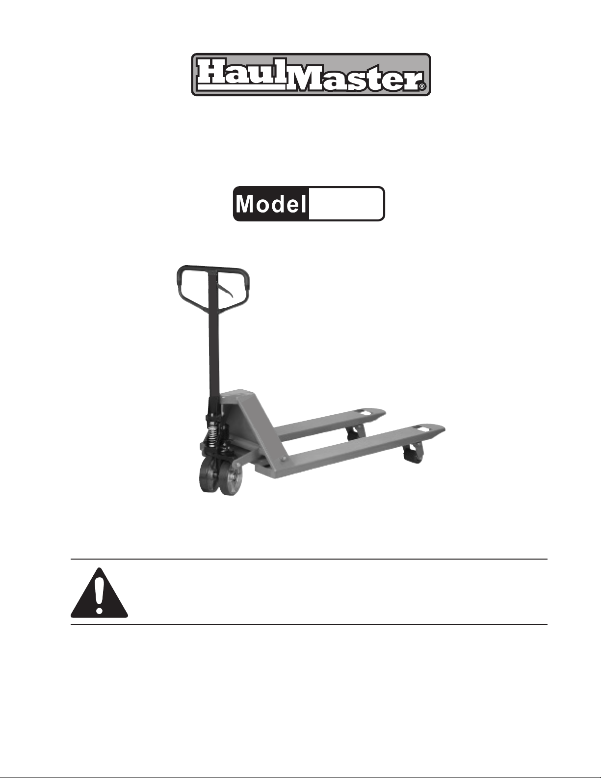
PALLET JACK - 2.5 TON
39939
SET UP AND OPERATING INSTRUCTIONS
Visit our website at: http://www.harborfreight.com
Read this material before using this product.
Failure to do so can result in serious injury.
SAVE THIS MANUAL.
Copyright© 1999 by Harbor Freight Tools®. All rights reserved. No portion of this manual or any artwork
contained herein may be reproduced in any shape or form without the express written consent of Harbor Freight
Tools. Diagrams within this manual may not be drawn proportionally. Due to continuing improvements, actual
product may differ slightly from the product described herein. Tools required for assembly and service may not
be included.
For technical questions or replacement parts, please call 1-800-444-3353.
Manual revised 09c
Page 2
SAVE THIS MANUAL
Keep this manual for the safety warnings and precautions, assembly, operating, inspection, maintenance and cleaning procedures. Write the product’s serial number in the back of the manual near the
assembly diagram (or month and year of purchase if product has no number). Keep this manual and the
receipt in a safe and dry place for future reference.
SPECIFICATIONS
Capacity 2.5 tons (5,000 lb.)
Fork Length 47-1/2”
Width Over Fork 27”
Lowered Height 3”
IMPORTANT SAFETY INSTRUCTIONS!
READ ALL INSTRUCTIONS BEFORE USING THIS PRODUCT!
Warning: The warnings, cautions and instructions discussed in this instruction manual cannot
cover all possible conditions and situations that may occur. It must be understood by the
operator that COMMON SENSE AND CAUTION ARE FACTORS WHICH CANNOT BE
BUILT INTO THIS PRODUCT, BUT MUST BE SUPPLIED BY THE OPERATOR.
The Operator
1. Do not operate the product if under the inuence of alcohol or drugs. Read warning labels on pre-
scriptions to determine if your judgment/reexes might be impaired.
2. Do not wear loose clothing or jewelry as they can be caught in moving parts.
3. Protective gloves and non-skid footwear is recommended.
4. Wear restrictive hair covering to contain long hair.
5. Wear ANSI approved impact safety goggles during setup and use.
6. Maintain proper footing and balance at all times.
7. Do not exceed the 2.5 Ton Load Capacity. Do not force the tool to do the work of a larger industrial
tool. It is designed to do the job better and more safely at the rate for which it was intended.
8. Before each use of the tool, carefully inspect the wheels, Handle Frame, Chassis and Handle for
proper operation. Do not use the Jack unless all components are operating properly.
Work Area
TO AVOID RISK OF PERSONAL INJURY, EQUIPMENT DAMAGE, FIRE AND SHOCK, MAKE SURE
YOUR WORK AREA IS:
1. Free of damp, wet or rainy conditions.
2. Free of children (do not let them handle tools or machinery).
3. Well-lit.
4. Clean and uncluttered.
REV 09c
SKU 39939 For technical questions, please call 1-800-444-3353. Page 2
Page 3

Before Operating
1. Before using any tool, any part that appears damaged should be carefully checked to determine
that it will operate properly and perform its intended function.
2. Before operating your Jack, check for damaged parts.
3. When raising, moving and lowering loads, keep individuals away from underneath the load.
4. Before moving a load, make certain that it is properly balanced.
5. Make sure all clamps, locks and bolts are tight.
Jack Specic Warnings
1. Do not place any part of the body in the lifting mechanism, or under the forks, or under the load.
2. Do not carry passengers on the Jack.
3. Use common sense when handling wide or long loads. Do not load unstable or loosely stacked
loads.
4. Do not exceed the 5,000 Lb. capacity - This capacity assumes an evenly distributed load with the
center of the load being at the halfway point of the length of the forks.
5. When not in use, lower the Jack forks to the lowest height.
6. Do not operate on a grade with loads too heavy to be easily handled by the operator.
7. Since this is a manually operated Jack, the operator must be physically capable of safely handling
the Jack and the load.
UNPACKING
When unpacking, make sure that the item is intact and undamaged. If any parts are missing or
broken, please call Harbor Freight Tools at the number shown on the cover of this manual as soon as
possible.
ASSEMBLY
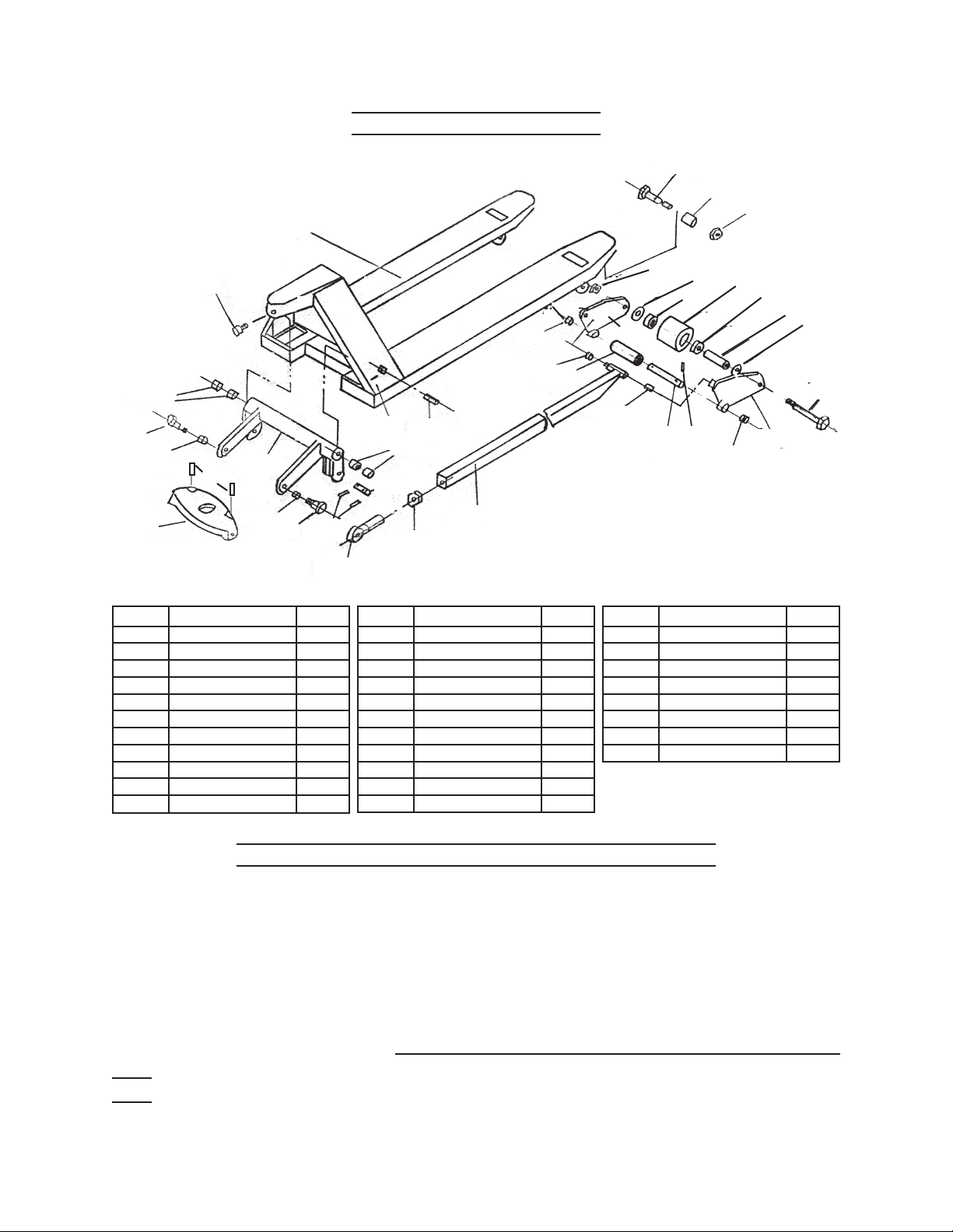
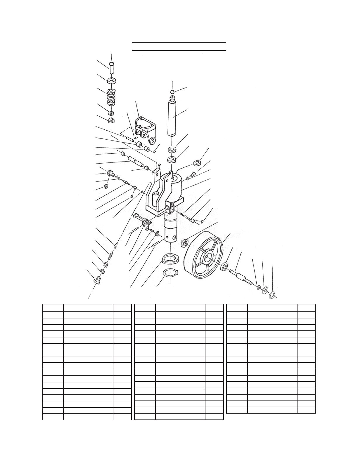
Your Jack will require some limited assembly. To assist you with assembly and operation please refer to
the Assembly Diagram and Parts List located on pages 6, 7, and 8.
Note: Tighten hardware to no more than 43 ft-lb using a torque wrench (not included).
1. Remove the three Bolts (L111) from the plastic bag.
2. Pass the Adjusting Bolt (L116) through the hole in the center of the Axle with Hole (L331) while you
set the Handle (L110) on the Bracket (L319).
3. Insert the three bolts (L111) through the Washers (L112) and the Handle, into the Bracket. Tighten
them.
4. Raise the Lever Plate (L345) and insert the Adjusting Bolt (L116) into the front slot, making sure to
keep the Adjusting Nut (L117) on the under side of the Lever Plate.
REV 09c
SKU 39939 For technical questions, please call 1-800-444-3353. Page 3
Page 4
OPERATION
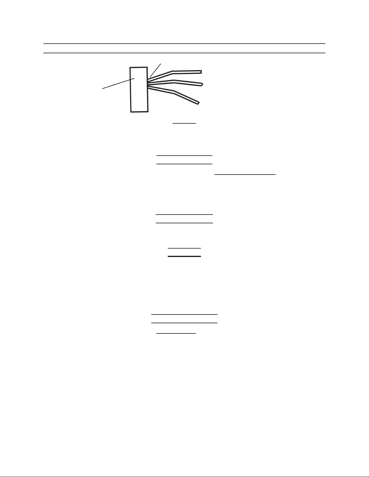
Control Handle
Upper Position (for Lowering Load)
Handle Frame
Figure 1
Located on the main part of the Handle of the Jack, you will nd the Control Handle (part #L108-
Handle) which can be set to three different positions. These three positions are for lifting, lowering and
locking the load. Please refer to Figure 1 as well as the instructions which follow.
Middle Position (For Moving Load)
Lower Position (for Lifting Load)
Lifting the Pallet
1. To raise the Forks, place the Control Handle (L108) in the lower position for lifting. The Control
Handle will be at its position closest to the oor. Pump the Handle Frame up and down to lift with
the Jack.
2. If the forks descend while pumping in the lower position, please adjust the Adjusting Nut or the Ad-
justing Screw as indicated under the section below called “Moving the Load-Adjusting.”
Moving the Load
To haul the load, place the Control Handle in the middle or neutral position. This will set the Pallet
in position so that the load can be transported.
Adjusting
1. If the forks lift while pumping while in the middle position, turn the Adjusting Nut (L117) on the
Adjusting Bolt (L116) clockwise. You can also turn the Adjusting Screw (L346) clockwise until any
pumping action does not raise the Pallet. This means the middle or neutral setting is working prop-
erly.
2. If the forks descend while pumping in the middle position, turn the Nut (L117) or the Screw (L346)
counter-clockwise until the forks no longer lower.
Lowering the Pallet
1. By setting the Control Handle to the Upper Position, you will lower the load. The Pallet will move to
its lowest position automatically.
2. If the forks do not lower when the Control Handle is in the Top position, turn the Adjusting Nut
(L117) or the Adjusting Screw as indicated under Moving the Load-Adjusting. If they still do not
lower, refer to Troubleshooting section.
SKU 39939 For technical questions, please call 1-800-444-3353. Page 4
Page 5
MAINTENANCE
Checking the Oil
IF THERE IS ANY QUESTION ABOUT A CONDITION
BEING SAFE OR UNSAFE, DO NOT OPERATE THE
TOOL.
1. Clean area around foot lever/valve after ev-
ery use. Lower jack completely after use.
2. Replace handle if pin breaks.
1. Only check the oil level when the Jack is in
a lowered position and parked on a level
surface.
2. Remove the Oil Plug on the Jack.
3. Oil should be level with the plug hole. If it is
not, add a high-quality hydraulic oil.
4. Check the seal before replacing the plug.
Troubleshooting
Problem Possible Causes Likely Solutions
The forks cannot
raise completely.
The forks will not
raise.
The forks will not
descend.
Fluid Leak. Component, likely seal, worn or
Forks descend
without operating
release valve.
Insufcient oil. Rell oil (see instructions above).
1. Insufcient oil.
2. Air in valve chamber.
1. Rell oil (see instructions above).
2. Raise the Control Handle to the Upper
position and pump the handle several times.
3. Old/contaminated oil.
1. Deformed piston rod.
2. Piston rod rusted.
3. Change oil and replace Seals.
1. Replace piston rod and cylinder.
2. Lubricate/replace rod. Keep jack in lowered
position when not in use.
3. Control handle, bolt, or chain
3. Replace the Handle Assembly.
broken or missing.
Inspect and replace worn or damaged parts.
damaged.
1. Contaminated oil clogging valve.
2. Hydraulic component damaged.
1. Clean valve with kerosene and change oil.
2. Replace damaged part.
Follow safety precautions whenever diagnosing or servicing the tool.
LIMITED 90 DAY WARRANTY
Harbor Freight Tools Co. makes every effort to assure that its products meet high quality and durability standards, and warrants to the original purchaser that this product is free from defects in materials and workmanship for
the period of 90 days from the date of purchase. This warranty does not apply to damage due directly or indirectly, to
misuse, abuse, negligence or accidents, repairs or alterations outside our facilities, criminal activity, improper installation, normal wear and tear, or to lack of maintenance. We shall in no event be liable for death, injuries to persons
or property, or for incidental, contingent, special or consequential damages arising from the use of our product. Some
states do not allow the exclusion or limitation of incidental or consequential damages, so the above limitation of exclusion may not apply to you. THIS WARRANTY IS EXPRESSLY IN LIEU OF ALL OTHER WARRANTIES, EXPRESS
OR IMPLIED, INCLUDING THE WARRANTIES OF MERCHANTABILITY AND FITNESS.
To take advantage of this warranty, the product or part must be returned to us with transportation charges prepaid. Proof of purchase date and an explanation of the complaint must accompany the merchandise. If our inspection
veries the defect, we will either repair or replace the product at our election or we may elect to refund the purchase
price if we cannot readily and quickly provide you with a replacement. We will return repaired products at our expense, but if we determine there is no defect, or that the defect resulted from causes not within the scope of our warranty, then you must bear the cost of returning the product.
This warranty gives you specic legal rights and you may also have other rights which vary from state to state.
3491 Mission Oaks Blvd. • PO Box 6009 • Camarillo, CA 93011 • (800) 444-3353
SKU 39939 For technical questions, please call 1-800-444-3353. Page 5
Page 6
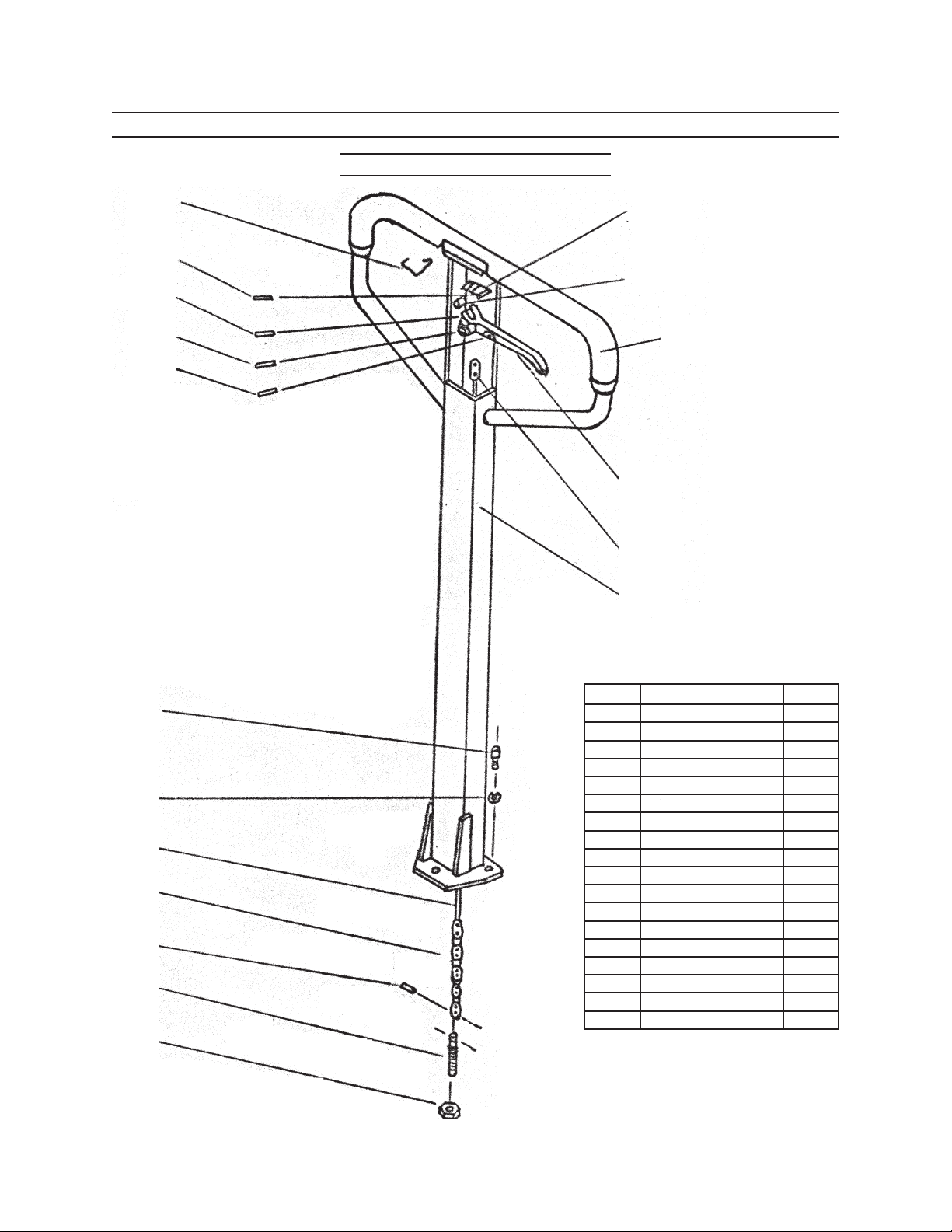
PARTS LISTS AND DIAGRAMS
Handle Parts List and Diagram
L101
L104
L105
L106
L107
L102
L103
L118
L108
L109
L110
Part Description Qty.
L111
L112
L113
L114
L115
L116
L101 Spring 1
L102 Blade Spring 1
L103 Roller 1
L104 Elastic Pin 1
L105 Elastic Pin 1
L106 Elastic Pin 1
L107 Elastic Pin 1
L108 Control Handle 1
L109 Pull Board 1
L110 Handle 1
L111 Bolt 3
L112 Elastic Washer 3
L113 Pull Rod 1
L114 Chain 1
L115 Pin 1
L116 Adjusting Bolt 1
L117 Nut 1
L118 Grip 1
L117
SKU 39939 For technical questions, please call 1-800-444-3353. Page 6
Page 7
L204
L207
L203
L205
L202
L246
L206
L205
L201
L204
Fork Parts List and Diagram
L219 L220
L213
L214
L203
L212
L208
L210
L209
L211
L216
L215
L216
L228
L217
L231
L223
L225
L218
L230
L229
L226
L225
L224
L223
L221
L220
L219
Part Description Qty.
L201 Chassis 1
L202 Lock Bolt 1
L203 Bushing 4
L204 Shoulder Bolt 2
L205 Bushing 2
L206 Torsion Tube 1
L207 Thrust Plate 1
L208 Elastic Pin 4
L209 Eye Bolt 2
L210 Nut 2
L211 Push Rod 2
Part Description Qty.
L212 Eye Bolt Axle 2
L213 Elastic Pin 2
L214 Torsion Tube Axle 2
L215 Roller 2
L216 Bushing 1
L217 Axle 2
L218 Elastic Pin 4
L219 Bushing 4
L220 Wheel Frame 4
L221 Bolt 2
L223 Washer 4
Part Description Qty.
L224 Wheel Axle 2
L225 Bearing 4
L226 Wheel 2
L228 Self-Locking Nut 2
L229 Nut 4
L230 Entry Roller 2
L231 Bolt 2
L246 Elastic Pin 2
PLEASE READ THE FOLLOWING CAREFULLY
THE MANUFACTURER AND/OR DISTRIBUTOR HAS PROVIDED THE PARTS LIST AND ASSEMBLY DIAGRAM
IN THIS MANUAL AS A REFERENCE TOOL ONLY. NEITHER THE MANUFACTURER OR DISTRIBUTOR MAKES
ANY REPRESENTATION OR WARRANTY OF ANY KIND TO THE BUYER THAT HE OR SHE IS QUALIFIED
TO MAKE ANY REPAIRS TO THE PRODUCT, OR THAT HE OR SHE IS QUALIFIED TO REPLACE ANY PARTS
OF THE PRODUCT. IN FACT, THE MANUFACTURER AND/OR DISTRIBUTOR EXPRESSLY STATES THAT
ALL REPAIRS AND PARTS REPLACEMENTS SHOULD BE UNDERTAKEN BY CERTIFIED AND LICENSED
TECHNICIANS, AND NOT BY THE BUYER. THE BUYER ASSUMES ALL RISK AND LIABILITY ARISING OUT OF
HIS OR HER REPAIRS TO THE ORIGINAL PRODUCT OR REPLACEMENT PARTS THERETO, OR ARISING OUT
OF HIS OR HER INSTALLATION OF REPLACEMENT PARTS THERETO.
Record Product’s Serial Number Here:
Note: If product has no serial number, record month and year of purchase instead.
Note: Some parts are listed and shown for illustration purposes only, and are not available individually as
replacement parts.
SKU 39939 For technical questions, please call 1-800-444-3353. Page 7
REV 09c; 11d
Page 8
L320
L321
Jack Parts List and Diagram
L322
L323
L324
L325
L326
L327
L330
L331
L332
L333
L334
L335
L336
L337
L339
L340
L341
L342
L343
L338
L328
L330
L344
L345
L346
L347
L319
L329
L318
L317
L316
L315
L314
L313
L312
L311
L310
L309
L308
L305
L306
L305
L304
L303
L302
L301
L348
Part Description Qty.
L301 Snap Ring 2
L302 Hub Cap 2
L303 Snap Ring 2
L304 Axle of Big Wheel 1
L305 Bearing 4
L306 Big Wheel 2
L308 O-Ring 2
L309 Release Valve 1
L310 Spring 1
L311 Cylinder Body 1
L312 Seal Washer 1
L313 Bolt 1
L314 Y-Seal 1
L315 Y-Seal 1
L316 Wiper 1
L317 Lift Piston 1
L349 L350
Part Description Qty.
L318 Ball 1
L319 Bracket 1
L320 Pump Piston 1
L321 Cap of Piston 1
L322 Spring 1
L323 Wiper 1
L324 Y-Seal 1
L325 Axle of Roller 1
L326 Pressure Roller 1
L327 Bushing 1
L328 Elastic Pin 1
L329 Elastic Pin 1
L330 Bushing 2
L331 Axle with Hole 1
L332 Plug Bolt 1
L333 Spring 1
L334 Seal Washer 1
Part Description Qty.
L335 Valve Pin 1
L336 Valve 1
L337 O-ring 1
L338 Ball 1
L339 Safe Valve Pin 1
L340 Spring 1
L341 Adjusting Bolt 1
L342 Seal Washer 1
L343 Plug Bolt 1
L344 Pin 1
L345 Lever 1
L346 Adjusting Screw 1
L347 Nut 1
L348 Elastic Pin 1
L349 Thrust Bearing 1
L350 Snap Ring 1
REV 09c
SKU 39939 For technical questions, please call 1-800-444-3353. Page 8
 Loading...