


Ex Line
Operating instructions
Discharging power pack
Ident number: 01.7960.000 (230 V), 01.7961.000 (115 V)
Keep for future use!
GB
Multistat Ex SDN


Table of contents
1 Operator instructions .................................................4
1.1 Symbols used in operating instructions ............................ 4
1.2 Symbols on the discharging power pack .......................... 5
2 Safety ..........................................................................6
2.1 Intended use ..................................................................... 7
3 Product overview........................................................8
4 Install ..........................................................................9
5 Operate ..................................................................... 15
5.1 Normal operation ............................................................ 15
5.2 Using the K6 signal socket for the operation................... 16
5.3 Using the K1 signal socket for the operation................... 17
5.4 Application example of a K1 signal socket ...................... 18
6 Troubleshooting ....................................................... 19
6.1 Replacing fuse................................................................. 20
6.2 Flow diagram 1 ................................................................ 21
6.3 Flow diagram 2 ................................................................ 22
7 Accessories/spare parts .......................................... 23
8 Technical data .......................................................... 25
8.1 Characteristics and specification ..................................... 25
8.2 Supply voltage ................................................................ 25
8.3 Ambient conditions ......................................................... 26
8.4 Housing ........................................................................... 27
9 Taking out of operation ............................................ 28
9.1 Storing ............................................................................. 28
9.2 Disposing ........................................................................ 28
1 Operator instructions
4
Always observe this safety instruction to avoid critical or fatal injuries.
Always observe this safety instruction to avoid damage to property.
NOTE:
Important notes and additional information.
1 Operator instructions
Before installation and commissioning read these operating
instruction in full. Always observe the safety instructions.
These operating instruction is a part of the product; make sure you
retain them for later use or subsequent owners.
1.1 Symbols used in operating instructions
The power pack is installed outside the EX-hazardous zone.
The discharging power pack is maintenance free and operationally
safe when used as intended.
The term “high voltage” is abbreviated HV in these operating
instructions (e.g. HV terminal).
The illustrations in this document are a simplified representation of
the product. They render only the technical facts and provide
support for the text. Departures from the actual product may be
noticeable. However, these deviations neither reduce the proper
function nor mitigate the specifications of the product.
1 Operator instructions
5
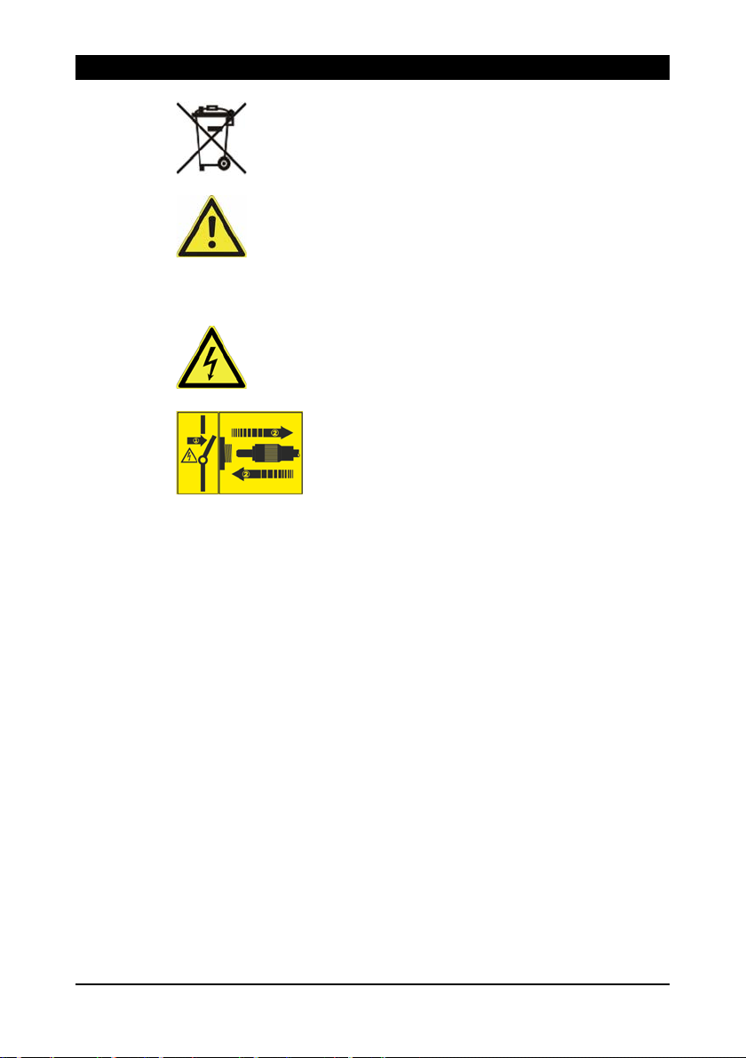
Never dispose of with household garbage.
General hazard!
WARNING!
ATTENTION!
1.2 Symbols on the discharging power pack
High voltage
Only plug in/unplug the ionizing unit at the HV
terminal when the discharging power pack is
switched off.
2 Safety
6
Hazards caused by manipulated or faulty discharging power
pack
Unauthorized modifications, moisture or damage to the discharging
power pack may result in
sparking.
•
•
•
•
•
•
discharging power pack or its components.
Damage to device and risk of fire
Short circuits can occur
voltage (HV)
connection point. This can lead to faults with the
pack and cause a fire.
•
•
plugs are
2 Safety
Only the persons authorized by the operator may carry out tasks on
the discharging power pack.
The installer must be a trained and qualified electrician and be
acquainted with the construction rules and country-specific
installation regulations for areas with potentially explosive
atmospheres. He must read the operating instructions in full.
The operator must read the operating instructions in full.
When working on the discharging power pack, switch off the voltage
supply and secure against inadvertent switching on.
electric shocks or fire hazards due to
For reasons of safety, never open or modify the discharging
power pack.
In the event of visible damage or suspected electrical defects,
take the discharging power pack out of operation immediately
and secure against inadvertent reuse.
Protect the discharging power pack from moisture.
Never carry out any unauthorized repairs to the discharging
power pack.
Always switch off the discharging power pack after use.
Do not keep any inflammable materials in the vicinity of the
as a result of soiling in the high-
The high-voltage connections and plugs must be clean, dry and
free of grease.
Use blind plugs to protect the unused HV connection points
against environmental influences. Ensure that the blind
clean, dry and free of grease.
discharging power
7
Risk of explosion!
The discharging power pack may generate sparks which ignite
gases, dust or similar substances.
•
potentially explosive atmospheres.
NOTE:
operating authorization will become null and void.
2.1 Intended use
Never install or use the discharging power pack in areas with
An operating authorization (ATEX) exists for the discharging power
pack. Only the HAUG Ex ionizing units listed in the operating
authorization must be connected. If other units are connected, the
The discharging power pack is intended exclusively for the supply of
alternating high voltage to HAUG ionizing units with X-2000
connector for use in potentially explosive atmospheres. In
combination with an ionizing unit for use in potentially explosive
atmospheres, electrostatic charges are neutralized in a production
process.
Always observe the installation and operating conditions indicated in
these operating instructions.
Warranty only covers products, accessories or spare parts of HAUG
GmbH & Co. KG.
2 Safety

3 Product overview
8
3 Product overview
Multistat Ex SDN
A fuse holder with fuse
(Replacing fuse, refer page
20)
B Reset button with fault lamp
C Power switch (is lit green if
the power pack is switched
on)
D K1 signal socket (for
monitoring functions)
E K6 signal socket (external
resetting, HV monitoring)
F Mains power input
G 4 HV connection points
H Earth connection point
(terminal)
I Retainer plate
J HV display

9
Risk of explosion!
The discharging
gases, dust or similar substances.
•
•
installation regulations for potentially explosive atmospheres.
Electric shock hazard!
An electric shock hazard results from a faulty connection of the
discharging power pack to the power supply.
• The discharge power pack may only be installed by a trained and
qualified electrician.
Damage to equipment!
Continuous overloading of the discharging power
failures.
•
• Never install the discharging power pack on a surface generating
• Never install at a location subject to direct solar irradiation.
NOTE:
operating authorization will become null and void.
4 Install
4 Install
power pack may generate sparks which ignite
Never install or use the discharging power pack in areas with
potentially explosive atmospheres.
Always observe the erection stipulations and country-specific
pack may result in
Never exceed the permissible connected length.
or radiating heat.
An operating authorization (ATEX) exists for the discharging power
pack. Only the HAUG Ex ionizing units listed in the operating
authorization must be connected. If other units are connected, the

4 Install
10
1. Check the model plate of the discharging power pack against the
ordering data. In the event of damage to the discharging power
pack, contact HAUG GmbH & Co. KG.
2. Before connecting, make
sure that the correct supply
voltage is available for the
discharging power pack.
• The model plate
attached to the housing
indicates the voltage.
• If the supply voltage is incorrect, the discharging power pack
may be damaged.
3. Place the discharging
power pack at the desired
location and attach with the
enclosed retaining plate, if
appropriate.
• The operation of the
discharging power pack
is not affected by the
position in which it is
installed.
• We recommend
installing the
discharging power pack
with the HV terminals
pointing downwards (to
protect them from
moisture, oil and dirt).
4. Ensure that the discharging
power pack is switched off.
11
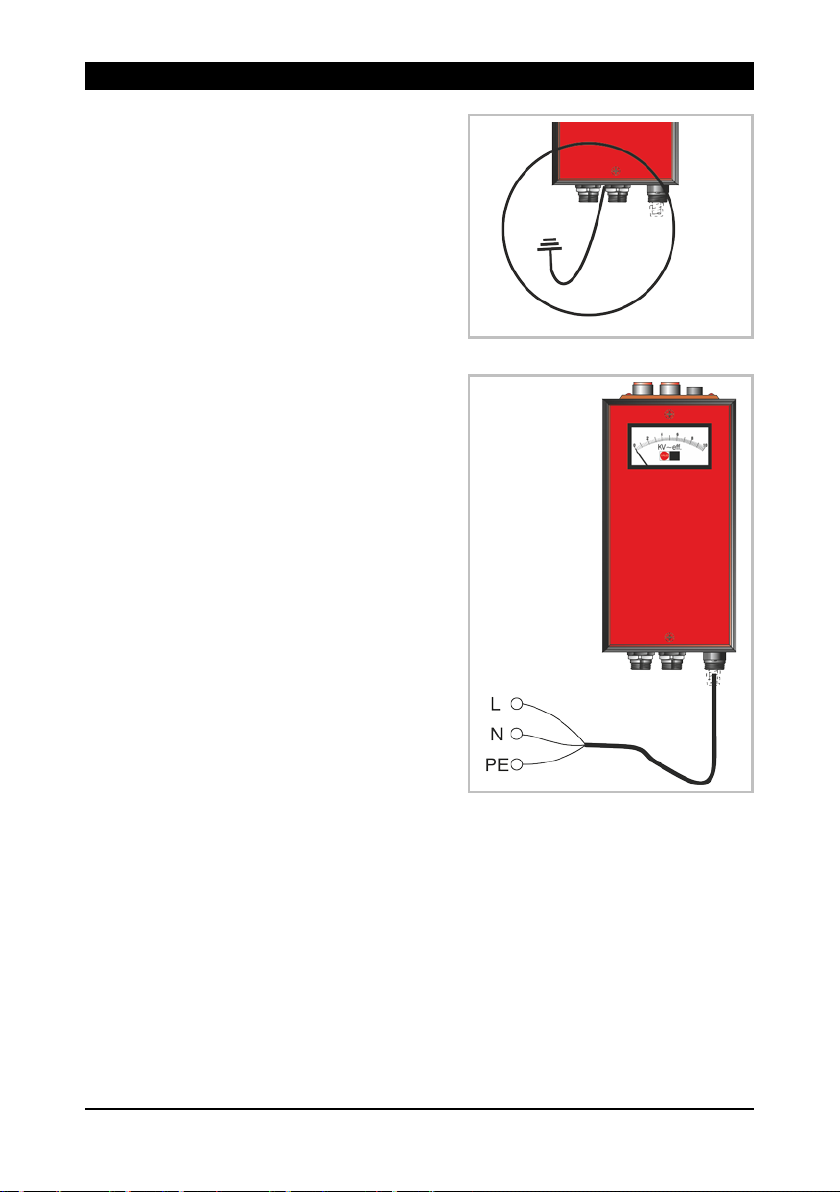
5. The ground socket of the
discharging power pack
must be connected to
ground potential in line with
applicable standards.
• Grounding cables of at
least 1,5 mm2 must be
used.
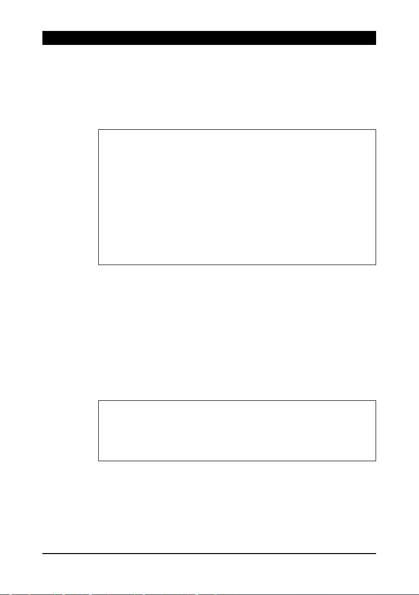
6. Connect the discharging
power pack to the supply
voltage. Always connect the
protective earth conductor
(green-yellow) with a
functioning protective earth
of the mains.
• Connecting the PE
conductor via parts of a
machine body is
insufficient.
• L = brown conductor
• N = blue conductor
• PE = green/yellow
conductor
4 Install

4 Install
12
When the ionizing un
discharging power pack is switched on, spark
HV connection. This may result in defects in the discharging power
pack.
• Switch off discharging power pack before plugging in/unplugging
ionizing unit.
NOTE:
and free of grease.
Contact and separation spark-overs!
it is plugged in or unplugged while the
-overs will occur at the
7. Connect the ionizing unit to
the HV terminal of the
discharging power pack.
• Insert the ionizing unit’s
HV plug in the HV
terminal of the
discharging power pack
and press the HV cable
until it reaches the stop.
• Screw the screw cap
onto the HV terminal and tighten by hand.
8. It is essential that the
grounding strap of the HV
plug is connected to the
grounding terminal of the
power pack.
Compliance with maximum connection length specifications is
required.
Use blind plugs to protect the unused HV connection points against
environmental influences. Ensure that the blind plugs are clean, dry

4 Install
13
Destructive electrical charges on the contacts of the K6 signalling
socket during the connection of the K6 signalling line may result in
defects in the discharging power pack.
•
be ensured by means of contact with grounded machine parts.
Operating conditions
Contacts 3
and 4 closed
Normal mode
Mains voltage
is available
HV is available
no
Internal fault
Mains voltage
is available
HV failure
yes
External fault
Power failure
Not defined
no
Damage to equipment!
To protect the electronic system of the unit, self-discharge shall
9. If necessary, connect the
signal line K6 to the K6
signal socket.
• Reset the power pack
externally.
• These HV connections
must be monitored.
• Relay contact load:
max. 24 V~ / 35 V=,
max. 50 mA
Configuration of the K6
signal socket:
A External reset (floating
normally open contact)
B Relay contact HV failure
Switching condition table for pin 3 and 4

4 Install
14
Destructive electrical charges on the contacts of the K6 signalling
socket during the connection of the K6 signalling line may result in
defects in the discharging power pack.
•
be ensured by means of contact with grounded machine parts.
Operating conditions
Contacts closed
Normal
mode
Mains voltage
is available
HV is available
1 and 3
5 and 6
internal
fault
Mains voltage
is available
HV failure
1 and 3
4 and 6
external
fault
Power failure
not defined
1 and 2
5 and 6
Damage to equipment!
To protect the electronic system of the unit, self-discharge shall
10. If necessary, connect the
signal line K1 to the K1
signal socket.
• Monitoring the function
of the power pack.
• Relay contact load:
max. 24 V~ / 35 V=,
max. 50 mA
Configuration of the K1
signal socket:
A Relay contact for power
failure
B Relay contact for
operational failure
Switching condition table for the K1 signal socket
More information in chapter "Using the K1 signal socket for the
operation" on page 17.
11. The discharging power pack is ready for operation.
15
NOTE:
Refer page 19.
NOTE:
“Troubleshooting”. Refer page 19.
5 Operate
Preconditions:
The discharging power pack and the ionizing unit are connected and
installed as specified in the operator instructions.
After a fault has occurred, the error lamp starts blinking. The power
pack switches off the HV.
The following occurances may have triggered the fault:
• The high-voltage on the HS output has dropped below ~ 4.2
• A flashover in the ionisation system may have been the cause.
• A short circuit in the ionisation system may have been the
Resetting the power pack is effected by triggering a reset. If a fault
persists, follow the instructions in the Chapter “Troubleshooting”.
5 Operate
kV.
cause.
5.1 Normal operation
Operating the power pack without monitoring it. K1 and K6 signal
sockets are not connected.
1. Use the power switch to turn on the power pack.
• To verify this, the green power switch is illuminated.
• The HV output voltage is indicated on the HV display of the
power pack.
• The power pack is running.
The flashing of the error indicator lamp indicates a defect. The
discharging power pack can be reset by pressing the reset
pushbutton. If the defect persists, refer to the following chapter

5 Operate
16
NOTE:
“Troubleshooting”. Refer page 19.
5.2 Using the K6 signal socket for the operation
Connecting the signal line K6 (accessory) to the K6 signals socket is
mandatory.
1. Use the power switch to turn on the power pack.
• To verify this, the green power switch is illuminated.
• The HV output voltage is indicated on the HV display of the
power pack.
• The power pack is running.
2. If an error occurs, pins 3 and 4 have continuity at the K6 signal
socket and the HV is switched off.
• The error lamp is blinking.
3. The HV can be switch on again by proceeding with a reset.
• To execute the external reset, close the potential-free normally
open contact (> 0.5 s) briefly.
• For a manual reset, simply press the reset button.
An error indication over the K6 signalling socket will indicate a fault.
The discharging power pack can be reset by triggering the external
reset. If the defect persists, refer to the following chapter
17
NOTE:
Refer page
19.
5.3 Using the K1 signal socket for the operation
Connecting the signal line K1 (accessory) to the K1 signals socket is
mandatory.
1. Use the power switch to turn on the power pack.
• To verify this, the green power switch is illuminated.
• The HV output voltage is indicated on the HV display of the
power pack.
• The power pack is running.
2. If a fault occurs, the HV is switched off.
• The error lamp is blinking.
• The signal line K1 can be used to evaluate an error message.
Refer page 18 "Application example of a K1 signal socket".
3. The HV can be switch on again by proceeding with a reset.
• To execute the external reset, close the potential-free normally
open contact (> 0.5 s) briefly. Only possible if a potential-free
normally open contact is connected via the K6 signal socket.
• For a manual reset, simply press the reset button.
A error message via the K1 signal socket indicates a fault. Resetting
the power pack is effected by triggering a reset. If a fault persists,
follow the instructions in the Chapter “Troubleshooting”.
5 Operate
5 Operate
18
High-voltage
Continuity (D and E)
Normal operation
no
Malfunction
yes
High-voltage
Continuity (D and E)
Normal operation
yes
Malfunction
no
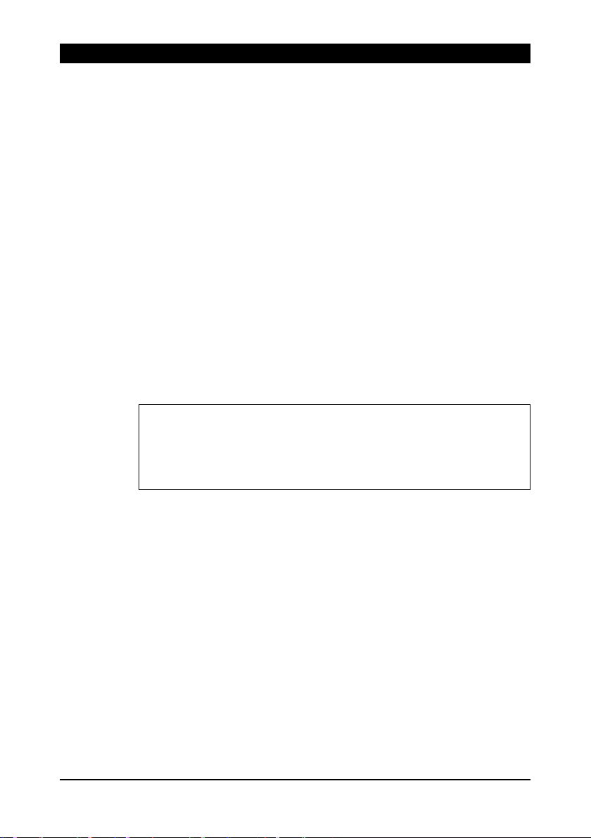
5.4 Application example of a K1 signal socket
Example 1:
A Relay contact for mains
failure
B Relay contact for HV failure
C1 Bridge 1
C2 Bridge 2
D Output
E Input
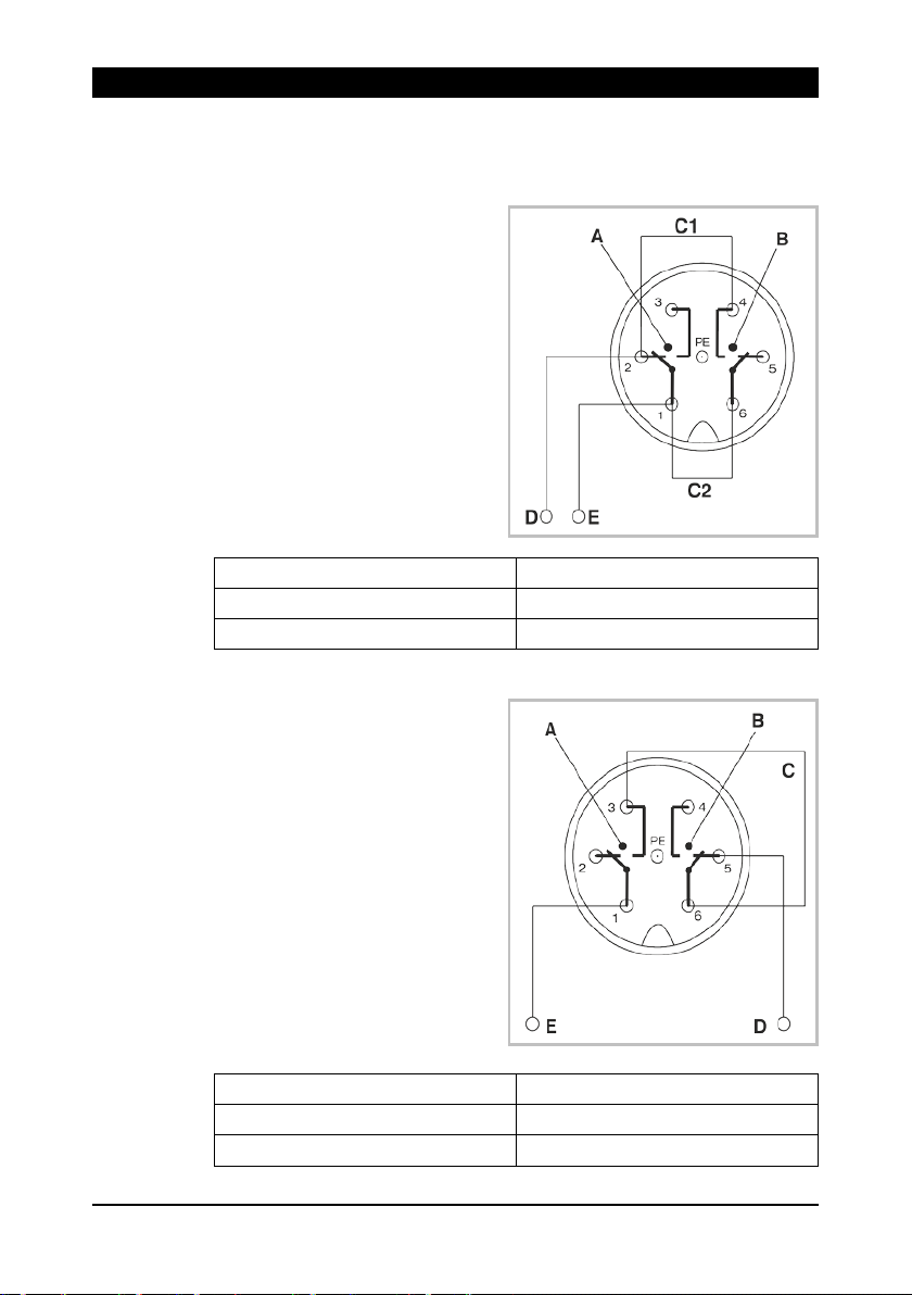
Example 2:
A Relay contact for mains
failure
B Relay contact for HV failure
C Bridge
D Output
E Input

19
Electric shock hazard!
The discharging power pack is operated electrically and generates a
high electric voltage. In the event of any faults, there is a risk of an
electric shock.
•
electrician.
NOTE:
power pack and ionizing unit for checking to HAUG GmbH & Co. KG
(the address is provided on the back of the envelope).
Fault
Cause
Troubleshooting
Ionization
Power
failure
Inspect the power fuse
HV not
Check the fuse of the discharging power
pack.
Inspect the connections on the
discharging power pack.
Use the Combicheck to verify the HV
(Accessories/spare parts, refer page 23)
Error lamp
The
is damaged
Shut down the discharging power pack
Ionizing unit
is dirty
Clean ionizing unit
Short circuit
Proceed with the work steps according
page 21.
Flashover
Proceed with reset
6 Troubleshooting
Faults may only be eliminated by a trained and qualified
If the error cannot be removed in this way, return the discharging
6 Troubleshooting
not
available
available
blinks or
error
discharging
power pack
message
output of the discharging power pack.
immediately and secure it to prevent
unintentional restart.
to the flow diagram shown below. Refer

6 Troubleshooting
20
Damage to equipment!
An incorrect fuse in the discharging power pack may cause a defect.
This may result in a cable fire.
•
•
• Never bridge the fuse.
6.1 Replacing fuse
Only use fuses of the specified type.
Never use repaired fuses.
The unit type and the rated voltage are indicated on the nameplate.
1. Disconnect discharging
power pack from supply.
2. Determine and remove the
cause for the blown fuse.
3. Detach the fuse holder (A)
using a screwdriver and lift
out.
4. Replace fuse and reattach
fuse holder.
Use the following fuse only:
• 115 V = 0,50 A slow, 5 x 20 mm
• 230 V = 0,25 A slow, 5 x 20 mm

21
The error lamp is blinking.
6.2 Flow diagram 1
Proceed with troubleshooting of all components exclusively outside
of the Ex zone.
Switch off the discharging power pack and unplug
the ionizing units.
Switch on the discharging power pack.
Is the error lamp blinking?
no
Switch off the discharging power pack and plug in an
ionizing unit.
Switch on the discharging power pack.
yes
Discharging power pack
defective
6 Troubleshooting
Is the error lamp blinking?
Switch off the discharging power pack and plug in
another ionizing unit.
Switch on the discharging power pack. etc.
Is the error lamp blinking?
Ionizing system is ok
no
no
yes
This ionizing unit is faulty.
(Short circuit)
yes
This ionizing unit is faulty.
(Short circuit)

6 Troubleshooting
22
Error message
6.3 Flow diagram 2
Proceed with troubleshooting of all components exclusively outside
of the Ex zone.
Switch off the discharging power pack and unplug
the ionizing units.
Switch on the discharging power pack.
Error message?
no
Switch off the discharging power pack and plug in an
ionizing unit.
Switch on the discharging power pack.
Error message?
yes
Discharging power pack
defective
yes
This ionizing unit is faulty.
(Short circuit)
no
Switch off the discharging power pack and plug in
another ionizing unit.
Switch on the discharging power pack. etc.
yes
This ionizing unit is faulty.
Error message?
(Short circuit)
no
Ionizing system is ok

23
Order
number
5 m shielded
signalling line K1 with
assembled plug
10 m shielded
signalling line K1 with
assembled plug
20 m shielded
signalling line K1 with
assembled plug
7 Accessories/spare parts
Accessories and spare parts can be sourced from your authorized
sales partner or directly from HAUG GmbH & Co. KG (the address is
provided on the back of the envelope).
Article Illustrations
7 Accessories/spare parts
Circular plug (K1)
Right-angle plug (K1)
X – 0616
X – 5718
06.8941.000
06.8941.001
06.8941.002

7 Accessories/spare parts
24
Order
number
5 m shielded
signalling line K6 with
assembled plug
10 m shielded
signalling line K6 with
assembled plug
20 m shielded
signalling line K6 with
assembled plug
Article Illustrations
Control plug (K6)
Combicheck
Blind plug for HV
terminals
X – 7807
06.8976.000
06.8976.001
06.8976.002
12.7231.000
X – 3521

25
HV terminals
4
High-voltage
6,7 ±1 kV~
Short-circuit current
Ik < 5 mA
Maximum connected length
18 m (ionizing bar + HV cable)
Reset pulse
> 0,5 s
Cannot be used in pulsed mode
Relay contact rating K1/K6
signalling socket
max. 24 V~/35 V=; max. 50 mA
Switching threshold for HV
< 4,2 kV
Switching threshold for mains
failure
< 50 V
Frequency
01.7960.000
230 V~ ±10 %
50 – 60 Hz
P
= 80 VA
01.7961.000
115 V~ ±10 %
50 – 60 Hz
P
= 80 VA
8 Technical data
8.1 Characteristics and specification
Reference temperature 23 °C
8 Technical data
8.2 Supply voltage
Unit type Nominal value
range
Power input
max
max

8 Technical data
26
Never use in potentially
explosive atmospheres.
Use indoors only.
Temperature:
Rated range of use
+5 to 45°C
Limit range for storage and
transport
-15 to 60°C
Relative humidity (RH):
Rated range of use
20% to 65% RH
Limit range for storage and
transport
0 % to 85 % RH
Compressed air:
Rated range of use
810 hPa to 1074 hPa
Vibrations:
Limit range for storage and
transport
max. 1.5 g (10 to 55 Hz), 1 h
Impact
max. 15 g in each direction
Recommended position for
operation:
HV connections pointing
downwards
8.3 Ambient conditions
27
Protection type
IP 54
Protection class
I
Mains supply
approx. 2,6 m fixed on unit
Dimensions:
Height
245 mm
Width
130 mm
Depth
130 mm
Weight:
5 kg
8.4 Housing
8 Technical data

9 Taking out of operation
28
Electric shock hazard!
The discharging power pack is operated electrical
high electric voltage. Improper decommissioning may result in
electric shock.
•
qualified electrician.
Never dispose of electrical appliances together with
9 Taking out of operation
Decommissioning may only be carried out by a trained and
1. Disconnect discharging power pack from supply.
2. Disconnect the mains line from the voltage supply.
3. Disconnect the ionizing unit from the HV terminal.
4. Disconnect the signalling line from the discharging power pack.
5. Remove the discharging power pack from the production
process.
9.1 Storing
Always store our products in a dry and cool place.
ly and generates a
9.2 Disposing
household garbage.
Always collect separately and dispose of in an
environmentally responsible way. Always observe
national and regional waste disposal regulations for
the disposal of electrical appliances.
If proper disposal of our products is not possible, returning the units
to us may be an option. We dispose of our products in an
environmentally responsible way. The address is provided on the
back of the envelope.

NOTES:
.............................................................................................................
.............................................................................................................
.............................................................................................................
.............................................................................................................
.............................................................................................................
.............................................................................................................
.............................................................................................................
.............................................................................................................
.............................................................................................................
.............................................................................................................
.............................................................................................................
.............................................................................................................
.............................................................................................................
.............................................................................................................
.............................................................................................................
.............................................................................................................
.............................................................................................................
.............................................................................................................
.............................................................................................................
.............................................................................................................
.............................................................................................................
.............................................................................................................
.............................................................................................................
.............................................................................................................
.............................................................................................................
.............................................................................................................
.............................................................................................................
.............................................................................................................


Multistat Ex SDN v02-1gb.docx
V02-1 • 17.09.2018 • D - 0370 - GB
made by
 Loading...