

INSTRUCTIONS
These instructions are intended for use only by experienced, qualified
nt and its components, by unqualified personnel,
These instructions are int ended to serve as guidelines c overing the ins tallat ion, operation, and mai ntenance of Hauc k equipment . W hile
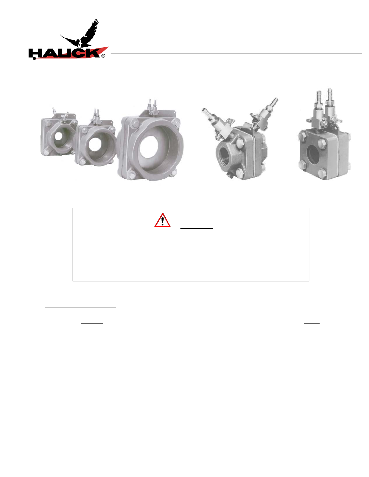
ORIFICE METERS
WARNING
TABLE OF CONTENTS
Subject
A. General Information..............................................................................................…… 2
B. Receiving and Inspection.....................................................................................…… 2
C. Installation..............................................................................................................….. 3
D. Manometer Adjustment...........................................................................................…. 3
E. Operation................................................................................................................…. 3
F. Maintenance............................................................................................................…. 4
Attached: Hauck Orifice Meter Capacity Charts
every attempt has been m ade to ensure completeness, unforeseen or unspec ified applications, details, and variations may preclude
covering every possible conti ngency. W ARNING: TO PREVENT THE POSSIBILITY OF SERIOUS BODILY INJURY, DO NOT USE OR
OPERATE ANY EQUIPMENT OR COMPONENT WITH ANY PARTS REMOVED OR ANY PARTS NOT APPROVED BY THE
MANUFACTURER. Should further information be required or desired or should particular problems arise which are not covered
sufficiently for t he purchaser's purpose, contac t Hauck Mfg. Co.
HAUCK MANUFACTURING CO., P.O. Box 90 Lebanon, PA 17042-0090 717-272-3051
3/99 www.hauckburner.com Fax: 717-273-9882
combustion start-up personnel.
Adjustment of this eq uipme
can result in fire, explosion, severe personal injury, or even death.
Page
OMG-9

For maximum accuracy provide 10 pipe diameters
of straight piping without fittings immediately
preceding the orifice meter and 5 pipe diameters
If the installation is delayed and the equipment is
stored outside, provide adequate protection as
dictated by climate and period of exposure.
Special care should be given to all motors and
, to protect them f rom rain or
OMG-9
A. GENERAL INFORMATION
The Hauck Orifice Metering System is a family of assemblies of thr eaded or welded design used for
measuring the flow of either com bustion air or any industrial gas. These meters m ay be used in the
main gas and air lines or in the gas and air lines of individual burners. The former configuration
allows the monitoring of total flow while the latter method allows precise setting of each burner .
B. RECEIVING AND INSPECTION
Upon receipt, check each item on the bill of lading/and or invoice to determine that all equipment has
been received. A careful examination of all part s should be m ade t o ascer t ain if there has been any
damage in shipment.
bearings, if applicable
excessive moisture.
C. INSTALLATION
1. Install the orifice meter in any position in the appropriate line. Most orifice m eters are available
in either of two configurat ions: one designed specifically for a welded connection, the other for
a threaded female connection. The location chosen for installation should permit easy access
to both pressure cocks and allow sufficient space t o r em ove the or ifice plate, if requir ed.
When used in the gas and air lines of individual burners, mount the orifice meter between a
flow control valve and the burner.
downstream of the orifice.
2. Insert and loosely tighten the three ( 3 ) connect ing bolts not required to hold the or ifice plate
in position.
3. Insert the orifice plat e and secur e it in place by insertion of the fourth connecting bolt.
Page 2
IMPORTANT
NOTE

OMG-9
4. Firmly tighten all bolts.
5. Insert a threaded plug in the unused cock openings.
D. MANOMETER ADJUSTMENT
1. Place the manometer on a rigid support.
2. Insert the proper amount of fluid into the manometer and adjust the fluid height until a 0.0"
manometer reading is obtained.
3. Connect the orifice meter pr essur e cocks to the manometer, using EQ UAL lengths of vinyl tub ing, such as Tygon, or equivalent.
E. OPERATION
The orifice metering system is designed so that the specific water column (wc) dif ferential observed
on the manometer corresponds to a specific flow rate through the orifice (for the specific plat e being
used).
1. Fully open the orifice meter pressure cocks.
Page 3

To reduce the risk of "blowing" the manometer
(forcing the f luid out of the manometer into the
tubing) tubing clips or valves can be located in
clips or valves are first closed and then
the orifice meter cock s are opened. The clips
or valves are then opened. Locating the
shutoff near the manometer minimizes the
gas volume being compressed when the
opposite leg of the manometer is opened to
Page 4
OMG-9
NOTE
the vinyl tubing lines near the manometer.
The
system pressure.
Reducing this volume limits movement of fluid
in the manometer.
2. Read the water column differ ent ial in inches and tenths of an inch. If t he r eading differs from
the desired reading, adjust the flow control valve until the manometer coincides with the de sired reading.
3. Fully close the orifice meter pressure cocks (and tubing clips if applicable).
4. Disconnect the connecting tubing, if desired.
F. MAINTENANCE
The design of the orifice plate and brackets requir es no ser vice or m aint enance.
If it ever becomes necessary to change the orifice plate:
1. Loosen all four (4) connecting bolt s .
2. Completely remove the plate positioning bolt.
3. Remove the old plate and insert the new one.
4. Securely tighten all connecting bolts.
Periodically check the quantity of fluid in the manometer and refill as r equired.

33 57 73 30 43 73 94
46 80
42 60
62
57 80
85
78
45 78
41 58
60
55 77
86
79
62
57 80
87
80
86
79
Page 5
OMG-9
OMG SERIES ORIFICE METERS
AIR & NATURAL GAS FLOW CAPACITY (SCFH)
100 – 200 Series Threaded / Weld-In
Pipe
Size
OMG
Model
Number
Orifice
Bore
Size
0.197 24
0.232 33
3/8" 103
0.266 44
0.307 61
0.350 84
0.232 32
0.266 42
1/2" 105
0.317 61
0.368 85
0.423 118
0.273 44
0.324 62
3/4" 107/207
0.379 86
0.437 116
0.508 162
0.585 221
0.324 61
0.384 86
1" 110/210
0.452 120
0.523 163
0.613 231
0.715 331
0.456 120
0.533 165
1 ¼" 112/212
0.630 233
0.735 324
0.850 447
0.986 641
0.533 164
0.635 234
1 ½" 115/215
0.744 325
0.867 450
1.005 626
1.156 881
Notes:
1. Orifice Bore Size Equals The Ori fice Plate Inside Diameter. All Bore Sizes In Inches. Pipe Size Equal s Schedule 40 Pipe.
2. Capacity Based On 60°F @ 1 psig Ups t ream Pressure. Natural Gas Specific Gravity At 0. 60; Air Specific Gravity At 1.0.
3. 1__ Model Number Designates NPT Threaded Connect i on. 2__ Model Number Designates Weld-In Connection.
4. All Flow Rates At Standard Barometric Pressure: 29.92" Hg (Sea Level).
5. Design Capacity Is Based On 3" W.C.ΔP.
9/98
3/8" Through 1 ½" Pipe Size
Air Natural Gas
0.5"
w.c.Δ
P
1"
w.c.Δ
P
3"
w.c.ΔP
107
147
118
203
103
149
120
166
206
286
107
151
121
163
228
322
208
282
394
555
149
122
170
230
326
467
170
233
330
457
632
905
232
331
459
636
885
1245
210
293
398
562
806
294
403
570
790
1092
1564
400
572
794
1100
1530
2151
5"
w.c.ΔP
103
137
189
261
100
133
191
265
368
137
194
268
363
507
714
192
270
378
513
724
1039
379
520
734
1018
1407
2015
516
737
1023
1417
1972
2771
0.5"
w.c.ΔP
108
109
152
110
149
208
294
111
155
211
297
427
155
213
301
418
577
827
212
302
419
581
808
1137
1"
w.c.Δ
P
110
152
111
154
214
113
156
211
294
415
111
157
219
297
420
602
219
301
425
590
815
1168
299
427
593
821
1142
1607
3"
w.c.ΔP
103
137
189
262
100
133
192
266
369
137
194
269
363
508
716
192
271
378
513
725
1040
379
520
735
1020
1409
2018
517
738
1024
1419
1974
2776
Continued
w.c.ΔP
5"
132
177
244
336
129
171
247
342
475
177
250
346
468
654
921
247
349
487
661
935
1340
488
671
947
1314
1816
2600
666
951
1320
1829
2544
3576

OMG-9
Page 6
OMG SERIES ORIFICE METERS
AIR & NATURAL GAS FLOW CAPACITY (SCFH)
100 – 200 Series Threaded / Weld-In
2" Through 6" Pipe Size
Pipe
Size
2" 120/220
2 ½" 125/225
3" 130/230
4" 140/240
6" 160/260
Notes:
6. Orifice Bore Size Equals The Ori fice Plate Inside Diameter. All Bore Sizes In Inches. Pipe Size Equal s Schedule 40 Pipe.
7. Capacity Based On 60°F @ 1 psig Ups t ream Pressure. Natural Gas Specific Gravity At 0. 60; Air Specific Gravity At 1.0.
8. 1__ Model Number Designates NPT Threaded Connect i on. 2__ Model Number Designates Weld-In Connection.
9. All Flow Rates At Standard Barometric Pressure: 29.92" Hg (Sea Level).
10. Design Capacity Is Based On 3" W.C.ΔP.
OMG
Model
Number
Orifice
Bore
Size
0.640 238
0.754 334
0.875 455
1.034 650
1.203 911 1278
1.375 1250
0.754 330
0.890 464
1.048 651
1.236 926 1302
1.423 1266 1778
1.625 1730
0.894 462
1.056 649
1.252 923 1300
1.452 1262 1776
1.688 1753 2466
1.963 2483
1.261 919 1295
1.470 1258 1773
1.722 1748 2462
2.029 2479 3491
2.345 3418 4810
2.691 4731
1.735 1729 2439
2.067 2470 3484
2.437 3468 4890
2.879 4924 6941 11965 15408
3.314 6685 9420 16231 20897
3.850 9423 13272 22856 29419 12135 17101 29466 37931
4.388 13055
0.5"
w.c.Δ
P
w.c.Δ
18381 31638 40712 16809 23679 40781 52484
Air Natural Gas
1"
P
335
470
640
914
1753
465
652
916
2428
651
914
3489
6655 11440 14716
3"
w.c.ΔP
577
808
1100
1568
2192
3003
800
1123
1576
2237
3053
4164
1122
1575
2237
3056
4238
5993
2234
3056
4242
6009
8275 10648
4211
6011
8434 10863
5"
w.c.ΔP
743
1039
1415
2016
2817
3858
1030
1445
2027
2877
3925
5353
1444
2027
2879
3932
5452
7706
2877
3935
5461
7734
5425
7743
0.5"
w.c.ΔP
307
430
586
836
1170
1605
425
597
838
1191
1628
2223
595
836
1188
1625
2256
3193
1184
1621
2251
3192
4400
6088
2229
3184
4469
6344
8611 12140 20928 26946
1"
w.c.Δ
P
432
605
824
1175
1644
2253
599
840
1180
1676
2288
3123
839
1178
1674
2287
3174
4491
1670
2285
3173
4497
6195 10665 13725
8568 14741 18966
3146
4493
6305 10878 14011
8947 15429 19870
3"
w.c.ΔP
744
1041
1417
2019
2822
3865
1031
1447
2030
2881
3932
5362
1446
2030
2884
2938
5460
7719
2881
3941
5468
7746
5432
7754
w.c.Δ
5"
P
958
1339
1823
2597
3629
4967
1328
1863
2613
3707
5056
6894
1863
2614
3712
5068
7026
9929
3710
5075
7041
9971
6998
9988
 Loading...