

Hauck OMG-105, OMG-207, OMG-110, OMG-115, OMG-112 Instructions Manual
...
INSTRUCTIONS
These instructions are intended for use only by experienced, qualified
nt and its components, by unqualified personnel,
These instructions are int ended to serve as guidelines c overing the ins tallat ion, operation, and mai ntenance of Hauc k equipment . W hile
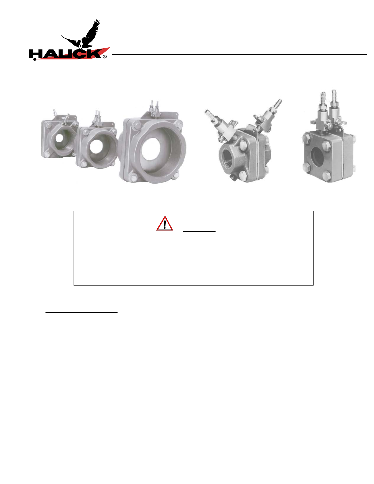
ORIFICE METERS
WARNING
TABLE OF CONTENTS
Subject
A. General Information..............................................................................................…… 2
B. Receiving and Inspection.....................................................................................…… 2
C. Installation..............................................................................................................….. 3
D. Manometer Adjustment...........................................................................................…. 3
E. Operation................................................................................................................…. 3
F. Maintenance............................................................................................................…. 4
Attached: Hauck Orifice Meter Capacity Charts
every attempt has been m ade to ensure completeness, unforeseen or unspec ified applications, details, and variations may preclude
covering every possible conti ngency. W ARNING: TO PREVENT THE POSSIBILITY OF SERIOUS BODILY INJURY, DO NOT USE OR
OPERATE ANY EQUIPMENT OR COMPONENT WITH ANY PARTS REMOVED OR ANY PARTS NOT APPROVED BY THE
MANUFACTURER. Should further information be required or desired or should particular problems arise which are not covered
sufficiently for t he purchaser's purpose, contac t Hauck Mfg. Co.
HAUCK MANUFACTURING CO., P.O. Box 90 Lebanon, PA 17042-0090 717-272-3051
3/99 www.hauckburner.com Fax: 717-273-9882
combustion start-up personnel.
Adjustment of this eq uipme
can result in fire, explosion, severe personal injury, or even death.
Page
OMG-9

For maximum accuracy provide 10 pipe diameters
of straight piping without fittings immediately
preceding the orifice meter and 5 pipe diameters
If the installation is delayed and the equipment is
stored outside, provide adequate protection as
dictated by climate and period of exposure.
Special care should be given to all motors and
, to protect them f rom rain or
OMG-9
A. GENERAL INFORMATION
The Hauck Orifice Metering System is a family of assemblies of thr eaded or welded design used for
measuring the flow of either com bustion air or any industrial gas. These meters m ay be used in the
main gas and air lines or in the gas and air lines of individual burners. The former configuration
allows the monitoring of total flow while the latter method allows precise setting of each burner .
B. RECEIVING AND INSPECTION
Upon receipt, check each item on the bill of lading/and or invoice to determine that all equipment has
been received. A careful examination of all part s should be m ade t o ascer t ain if there has been any
damage in shipment.
bearings, if applicable
excessive moisture.
C. INSTALLATION
1. Install the orifice meter in any position in the appropriate line. Most orifice m eters are available
in either of two configurat ions: one designed specifically for a welded connection, the other for
a threaded female connection. The location chosen for installation should permit easy access
to both pressure cocks and allow sufficient space t o r em ove the or ifice plate, if requir ed.
When used in the gas and air lines of individual burners, mount the orifice meter between a
flow control valve and the burner.
downstream of the orifice.
2. Insert and loosely tighten the three ( 3 ) connect ing bolts not required to hold the or ifice plate
in position.
3. Insert the orifice plat e and secur e it in place by insertion of the fourth connecting bolt.
Page 2
IMPORTANT
NOTE
 Loading...