

These instructions are intended for use only by experienced, qualified combustion startup personnel. Adjustment of this equipment by unqualified personnel can result in fire,
explosion, severe personal injury or even death.
To make changes to the burner or adjust firing inputs: 1. Shut the burner down; 2. Make
changes; 3. Restart the burner. STAND CLEAR OF THE BURNER UNDER ANY
FIRING CONDITIONS.
MEGASTARTMBURNER
MS-50 – MS-150
WARNING
INSTRUCTIONS
TABLE OF CONTENTS
These instructions are intended to serve as guidelines covering the installation, operation, and maintenance of Hauck equipment. While
every attempt has been made to ensure completeness, unforeseen or unspecified applications, details, and variations may preclude
covering every possible contingency. WARNING: TO PREVENT THE POSSIBILITY OF SERIOUS BODILY INJURY, DO NOT USE OR
OPERATE ANY EQUIPMENT OR COMPONENT WITH ANY PARTS REMOVED OR ANY PARTS NOT APPROVED BY THE
MANUFACTURER. Should further information be required or desired or should particular problems arise which are not covered
sufficiently for the purchaser's purpose, contact Hauck Mfg. Co.
HAUCK MANUFACTURING CO., 100 North Harris Street Cleona, PA 17042 717-272-3051
1/15 www.hauckburner.com Fax: 717-273-9882
Subject
A. General Information…………………………………………………………………… 2
B. Receiving & Inspection……………………………………………………………….. 2
C. Burner Capacities……………………………………………………………………... 3
D. Dimensions…………………………………………………………………………….. 5
E. Component Identification…………………………………………………………….. 6
F. Combustion Flighting…………………………………………………………………. 7
G. Burner Mounting………………………………………………………………………. 7
H. Fuel Manifold Installation……………………………………………………………... 8
I. Natural Gas Fuel Piping System…………………………………………………….. 9
J. Light Fuel Oil Piping System…………………………………………………………. 13
K. Heavy Fuel Oil Piping System……………………………………………………….. 15
L. Oil Manifold Heat Tracing…………………………………………………………….. 18
M. Heavy Oil Insert Heater………………………………………………………………. 18
N. Fuel Oil Nozzle………………………………………………………………………… 20
O. Compressed Air/Oil Atomizer………………………………………………………… 21
P. Liquid Propane (LP) Fuel Piping System…………………………………………… 26
Q. Liquid Propane (LP) Nozzle………………………………………………………….. 31
R. Burner Pilot System…………………………………………………………………… 33
S. Primary Air……………………………………………………………………………... 34
T. Burner Setup…………………………………………………………………………… 34
U. Operation………………………………………………………………………………. 35
V. Adjustments……………………………………………………………………………. 36
W. Maintenance…………………………………………………………………………… 37
X. Recommended Spare Parts…………………………………………………………. 38
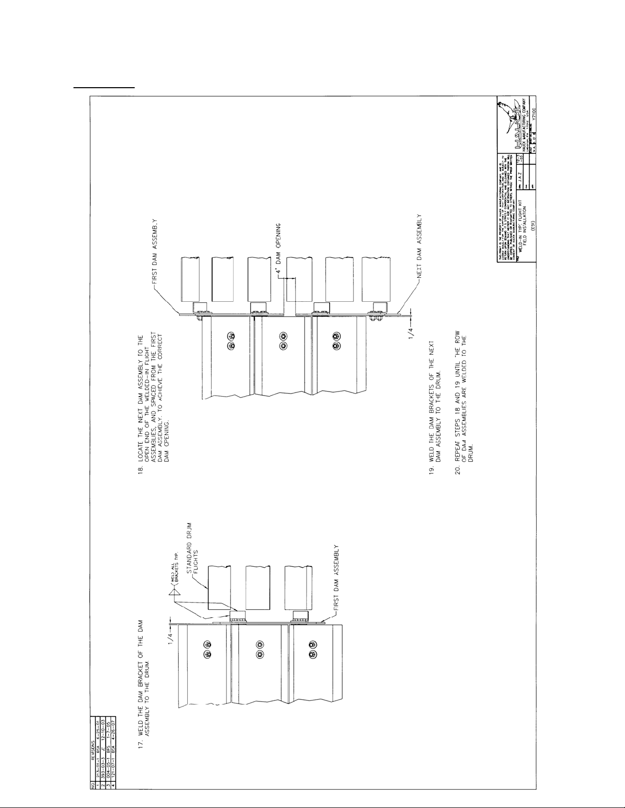
Appendix: Field Installation Weld-In Type flights, Y7100……………………….. 39
Required Reference: Appropriate Burner Data Sheet
GJ73 Dryer Drum Gas Analysis
GJ75 MegaStar Application Sheet
Page
MS-9
Page 2
MS-9
WARNING
This equipment is potentially dangerous with the possibility of serious personal injury
and property damage. Hauck Manufacturing Company recommends the use of flame
supervisory equipment and fuel safety shutoff valves. Furthermore, Hauck urges rigid
adherence to National Fire Protection Association (NFPA) standards and insurance
underwriter’s requirements. Operation and regular preventative maintenance of this
equipment should be performed only by properly trained and qualified personnel.
Annual review and upgrading of safety equipment is recommended.
A. GENERAL INFORMATION
The MegaStar
TM
Burner is the next generation of total air aggregate drying burners. It has the
same quiet operation and ecological benefits as its predecessors, with the improved efficiency,
emissions, and ease of operation. It is available with low pressure atomization for light fuel oils
or LP, and is a highly efficient natural gas or vaporous propane burner. It features our lowest
construction profile allowing for easier installation and easier access to working components on
the burner. Flame adjustability allows a tailored fit to any drum configuration. Air/fuel ratio for the
MegaStar burner can be maintained more precisely than ever before over the entire operating
range by an energy saving VFD for maximum efficiency.
The MegaStar
TM
can be supplied with fuel manifolds as an integral part of the burner, or with
optional remote rack mounted fuel manifolds. Natural gas firing does not require a primary air
blower.
The MegaStar
ultraviolet flame scanner. If an alternate flame scanner is
required, consult Hauck.
TM
is supplied with a Honeywell C7027A
NOTE
B. RECEIVING AND INSPECTION
Upon receipt, check each item on the bill of lading and/or invoice to determine that all
equipment has been received. A careful examination of all parts should be made to ascertain if
there has been any damage in shipment.
If the installation is delayed and the equipment is stored outside,
provide adequate protection as dictated by climate and period of
exposure. Special care should be given to all motors and
bearings, if applicable, to protect them from rain or excessive
moisture.
IMPORTANT
Page 3
MS-9
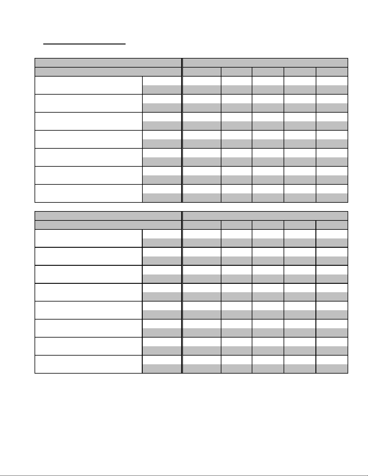
C. BURNER CAPACITIES
Capacity
Main Ai r Flow
Main Air Pressure
Gas Flow Rate
Capacity with Flue Gas Recirc
Flame Length @ 30° Spin
Flame Diameter @ 30° Spin
MEGASTAR BURNER MODEL
GAS SPECIFICATIONS
(MMBTU/hr)
(MW) 14.7 24.2 29.3 39.6 45.2
(scfh) 636,600 1,050,000 1,270,000 1,720,000 1,960,000
3
/hr)
(nm
(in.w.c.) 14.3 12.6 15.3 13.8 14.5
(mbar) 35.6 31.3 38.1 34.3 36.1
(scfh) 52,300 86,200 104,300 141,300 161,000
3
(nm
/hr)
(MMBTU/hr)
(MW) 11.0 16.8 22.2 27.9 33.6
(ft) 12 14 9 11 15
(m) 3.7 4.1 2.7 3.4 4.6
(ft) 4 7587
(m) 1.2 2.0 1.5 2.4 2.1
50 75 100 125 150
54 89 108 146 166
17,100 28,100 34,000 46,100 52,500
1,400 2,300 2,800 3,800 4,300
40.5 62 82 103 124
Capacity
LIGHT OIL SPECIFICATIONS
Main Ai r Flow
Main Air Pressure
Primary Air Flow
Primary Air Pressure
Oil Flow Rate
Flame Length @ 30° Spin
Flame Diameter @ 30° Spin
MEGASTAR BURNER MODEL
50 75 100 125 150
(MMBTU/hr)
(MW) 14.3 22.3 27.2 36.5 41.5
(scfh) 643,300 1,030,000 1,270,000 1,720,000 1,960,000
3
/hr)
(nm
(in.w.c.) 14.3 12.0 16.2 13.7 144.0
(mbar) 35.6 29.9 40.3 34.1 358.3
(scfh) 46,500 46,500 46,500 46,500 46,500
3
/hr)
(nm
(in.w.c.)62 62626262
(mbar) 154 154 154 154 154
(gal) 370 580 710 950 1,080
(lph) 1,400 2,200 2,690 3,600 4,090
(ft) 10 12 12 10 12
(m) 3.1 3.7 3.7 3.1 3.7
(ft) 4 5545
(m) 1.2 1.5 1.5 1.2 1.5
53 82 100 135 153
17,200 27,600 34,000 46,100 52,500
1,200 1,200 1,200 1,200 1,200
Table 1. Burner Capacity Data For Natural Gas & Light Oil
Page 4
MS-9
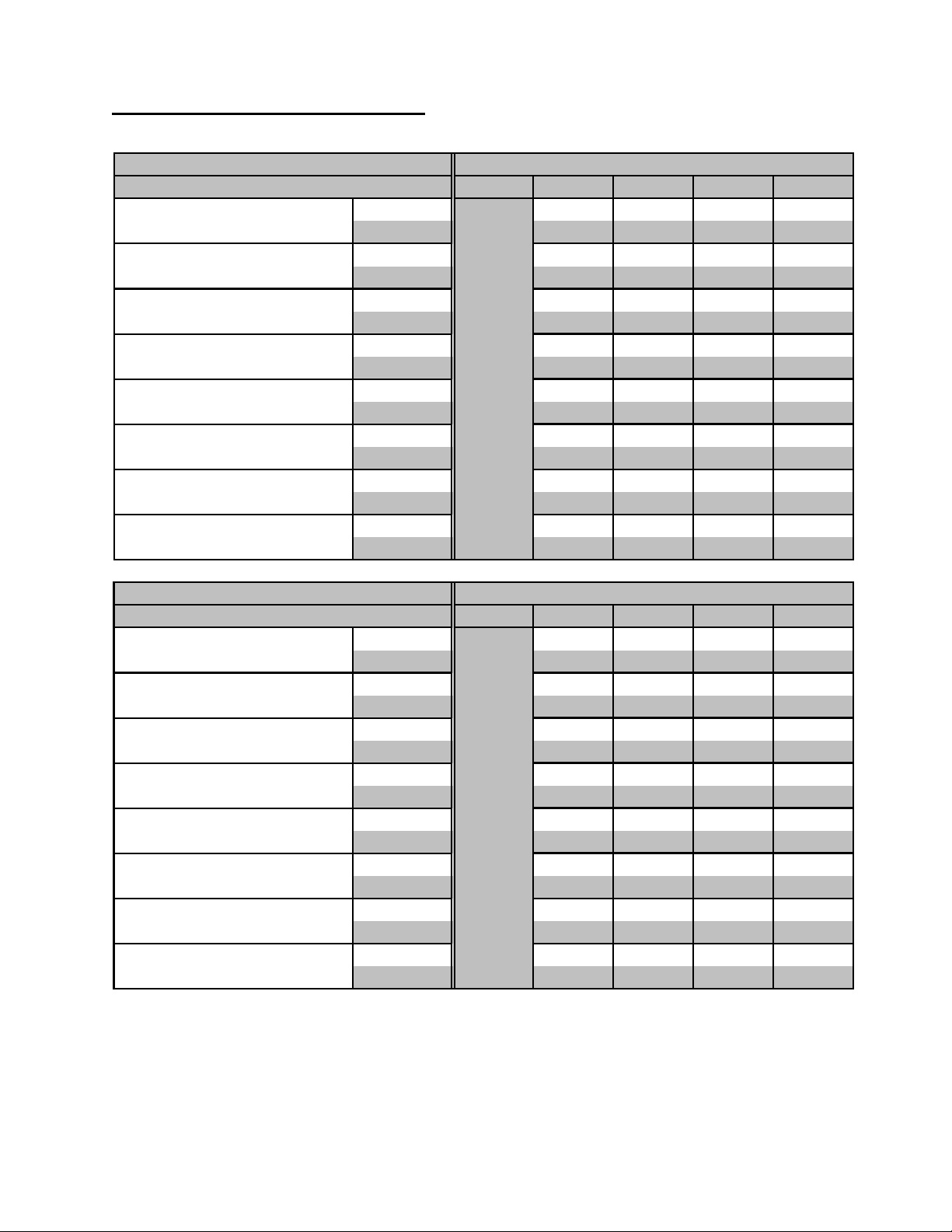
C. BURNER CAPACITIES (Continued)
LIQUID PROPANE SPECIFICATIONS
Capacity
Main Air Flow
Main Air Pressure
Primary Air Flow
Primary Air Pressure
Propane Flow Rate
Flame Length @ 30° Spin
Flame Diameter @ 30° Spin
MEGASTAR BURNER MODEL
50 75 100 125 150
(MMBTU/hr)
(MW) 21.7 26.4 34.6 39.3
(scfh) 980,000 1,200,000 1,590,000 1,810,000
3
/hr)
(nm
(in.w.c.) 12.8 18.5 15.0 18.3
(mbar) 31.8 46.0 37.3 45.5
(scfh) 46,500 46,500 46,500 46,500
3
/hr)
(nm
(in.w.c.) 62626262
(mbar) 154 154 154 154
(gal) 880 1,070 1,400 1,590
(lph) 3,330 4,050 5,300 6,020
(ft) 14 15 13 15
(m) 4.3 4.6 4.0 4.6
(ft) 5566
(m) 1.5 1.5 1.8 1.8
P
e
n
d
i
n
g
80 97 128 145
26,300 32,100 42,600 48,500
1,200 1,200 1,200 1,200
COMPRESSED AIR SPECIFICATIONS
Capacity
Main Air Flow
Main Air Pressure
Compressed Air Flow
Compressed Air Pressure
Oil Flow Rate
Flame Length @ 30° Spin
Flame Diameter @ 30° Spin
MEGASTAR
BURNER MODEL
50 75 100 125 150
(MMBTU/hr)
(MW) 21.4 27.2 35.3 40.7
(scfh) 1,030,000 1,310,000 1,700,000 1,960,000
3
/hr)
(nm
(in.w.c.) 12.0 16.2 13.2 14.4
(mbar) 29.9 40.3 32.8 35.8
(scfh) 3,600 3,600 5,400 5,400
3
/hr)
(nm
(psig) 60 60 60 60
(bar) 4444
(gal) 560 710 920 1,060
(lph) 2,120 2,690 3,480 4,010
(ft) 9 9 10 10
(m) 2.7 2.7 3.1 3.1
(ft) 5555
(m) 1.5 1.5 1.5 1.5
N
o
t
A
v
a
i
l
a
b
l
e
79 100 130 150
27,600 35,100 45,500 52,500
100 100 100 100
Table 2. Burner Capacity Data For Liquid Propane & Compressed Air

Page 5
MS-9
C. BURNER CAPACITIES (Continued)
Table 1 & 2 Notes:
1. Burner capacity is based on 60Hz power and scfh (nm3/hr) 60F (0°C) air at sea level.
Correction factors must be applied for variations in altitude, temperature, or frequency;
consult Hauck. An altitude correction table is available in Hauck Application Sheet GJ75.
2. Natural gas capacities based on higher heating value of 1,034 Btu per cubic foot (lower
heating value of 36.74 MJ/nm
air, and stoichiometric ratio of 9.74:1.
3)
, 2-4 psig (138 – 276 mbar) manifold pressure, 25% excess
3. No. 2 fuel oil capacities based on higher heating value of 141,146 Btu per gallon (lower
heating value of 36.99 MJ/liter), 35% excess air, and stoichiometric ratio of 1371.1 cubic feet
air/gallon of No. 2 oil (9.7 nm
3
air/liter).
4. Liquid propane capacities based on higher heating value of 90,912 Btu per gallon (lower
heating value of 23.83 MJ/liter), 35% excess air, and stoichiometric ratio of 864 cubic feet
air/gallon of liquid propane (6.1 nm3 air/liter).
5. The exhaust fan must be able to provide a slight negative pressure, suction in the range of
0.25 to 1” wc (.6 to 2.5 mbar), at the burner breech plate to exhaust the products of
combustion.
6. MegaStar
TM
Burner airflow can be accurately monitored using the body pressure tap on
either side of the burner air plenum. An accurate device capable of reading up to 15" wc (75
mbar) will be required for this measurement.
7. All burner fuel manifolds are supplied with fuel flow measuring devices. Liquid fuel
manifolds are equipped with an inline flow meter. Gaseous fuel manifolds are equipped with
a gas orifice meter that can be accurately checked for gas flow by measuring the differential
pressure across the orifice meter with a U-tube device (manometer) capable of reading in
the range of 0 to 20"wc (0 to 50 mbar).
8. Low pressure atomizing air, used for firing low pressure fuel oil or LP, is provided by a 36 osi
(155 mbar) Hauck high efficiency Turbo Blower. The low pressure air is used to not only
atomize liquid fuels, but also improve mixing speed in the combustion zone.
9. High pressure compressed air, used for firing heavy oils or any fuel oil at high elevations,
must be supplied by the customer at a nominal 60 psig (4140 mbar) to the burner nozzle for
optimum fuel oil atomization.
D. DIMENSIONS
See appropriate section of MS-3 for detailed dimensional information.
Page 6
MS-9
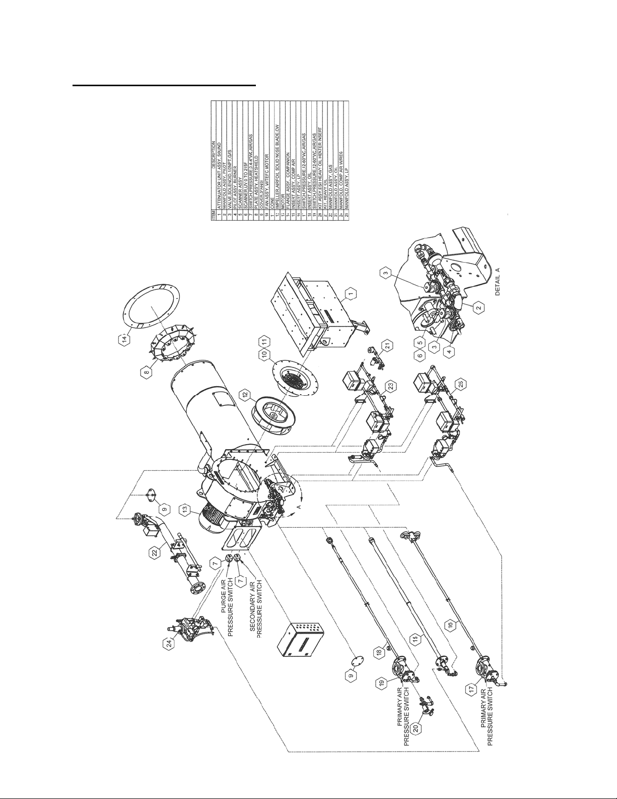
E. COMPONENT IDENTIFICATION
Y8978
Figure 1. MegaStarTM Burner Components
(NOT TO SCALE)

Page 7
TM
MS-9
F. COMBUSTION FLIGHTING
Flight design in the combustion zone is very important. Correct flighting can minimize pollutant
emissions, and provide heat shielding to keep the drum surface temperature down. To obtain
complete combustion, the combustion zone must be sized to provide enough combustion
volume for the flame to burn, and it should also be clear of veiling material that can quench the
flame, resulting in poor combustion efficiency.
Combustion flights provide protection for the drum by shielding it from direct flame radiation.
Construction of the combustion flights should be such that no material is allowed to fall through
the flame. Combustion flights should also have a means of dissipating heat to prevent their
destruction by the flame. This is typically done by plowing material over the fights and keeping
the flights as low as possible to the drum. Consult Hauck for details on flight design and
combustion zone requirements.
Flights are available from Hauck to optimize performance of the MegaStar™ on a rotary dryer;
for detailed installation instructions of Hauck weld-in type flights, see Y7100 in the Appendix.
For additional information on application issues for an MegaStar™ on a rotary dryer, see Hauck
Application Sheet GJ75.
G. BURNER MOUNTING
For MegaStar™ burners with an extended burner nose length, the nose must be
supported to avoid undue strain on the burner housing. Consult dryer
manufacturer for extended burner nose support recommendations.
IMPORTANT
1. The burner should be mounted on the drum centerline at the same pitch as the drum. Install
a structure to support the burner. Refer to dimensional drawings in the Section D. The
support structure must be able to support the weight of the burner (see Table 3). If the
optional primary air turbo blower (TBA) is to be mounted on the same structure as the
burner, allow for the additional weight. Consult Hauck for recommended burner mounting
options. If applicable, choose a suitable location for the optional remote mounted fuel rack
and primary air TBA blower. The fuel rack should be firmly attached to the base structure or
concrete pad. The fuel rack is supplied with mounting holes in the base angle iron. Consult
Hauck for the remote mounted fuel rack dimensional drawing Y6967 if applicable. Consult
TBA blower instruction sheet (TBA-9) for proper mounting instructions for the primary air
TBA blower.
2. The burner is supplied with lifting eyes to facilitate lifting the burner into place. Do not use
the lifting eye on the main blower motor for lifting the entire burner unit. The optional
TBA blower is also supplied with lifting eyes on the blower frame. Do not use the motor
lifting eye to lift the entire blower unit.
MegaStar
Approx. Net Weight* (lb)
[kg]
Model No. 50 75 100 125 150
2,500
[1,130]
5,000
[2,270]
5,800
[2,630]
6,500
[2,950]
6,500
[2,950]
Table 3. MegaStar™ Approximate Burner Net Weights
Page 8
MS-9
3. The burner can be ordered with a split-mounting companion flange that can be bolted onto
the dryer breech plate (see Table 4). This allows positioning the burner at various insertion
depths past the breech plate. Typical burner insertion depth is 18 to 24" (460 to 610mm).
Cut out a hole in the breech plate 2" (50mm) in diameter larger than the burner tube. Do not
weld the split-mounting flange to the burner body, as the breech will expand and contract
with changes in temperature. If the split-mounting flange is welded to the burner, heat and
stress will damage the burner. Tightly seal the burner to the breech. If using oil as a primary
fuel, the insertion depth may have to extend more than 24" (610mm) due to the amount of
radiant heat from an oil flame depending on the application.
MegaStar
TM
Model No. 50 75-100 125-150
Companion Flange Part No. 407091 56548x001 56549x008
Table 4. MegaStarTM Burner Recommended Split-Mounting Companion Flange
4. Bolt the burner to the support structure.
5. Wire the main fan motor and the optional TBA blower motor (if applicable) per instructions
on the motor.
6. Rotation of all blowers must be checked prior to burner startup. The rotation is marked with
an arrow on the blower housings. Do not operate the burner until all blowers are
checked for rotation and are rotating correctly.
All rotating components were balanced from factory at a level meeting ISO 1940-2. A variety
of external causes such as handling, installation, or misalignment may cause imbalance prior
to use. To ensure the intended long life of the equipment and components, and to meet
warranty requirements, equipment and vibration levels should be checked by experienced
personnel and trim balanced if no longer meeting ISO 1940-2 requirements. Under no
circumstances should equipment with excessive vibration be operated at the risk of damaging
that equipment or the personnel operating it.
NOTE
H. FUEL MANIFOLD INSTALLATION
The MegaStarTM burner can be supplied with integral fuel manifolds on the burner or with
optional remote rack mounted fuel manifolds. The fuel manifold has all modulating fuel valves
mounted on it. In addition to modulating fuel valves, the manifold includes the automatic oil, gas
and LP safety shutoff valves.
Fuel manifolds must be mounted in a horizontal position. Safety shutoff valves will not function
properly if mounted vertically. Liquid fuel manifolds should not be mounted above the burner
centerline. Oil and LP manifolds should be mounted as close to the burner as possible. For heavy
fuel oil applications, i.e., any fuel requiring heating for use, oil piping must be heat traced (electric
or steam) and insulated. Self-regulating heat tracing is recommended to maintain the desired
temperature of a given fuel oil to achieve 90 SSU (1.8x10
heat tracing with a nominal rating of 12W/ft (39W/m) covered with a nominal 2" (50mm) fiberglass
type insulation is sufficient for most applications. Fuel oil temperature should not exceed 250°F
(120°C). Oil viscosity should be checked prior to burner operation.
Hauck recommends the use of schedule 40 iron pipe and fittings rated for 150 psig (10.3 bar) for
natural gas and oil system interconnecting piping. LP applications require the use of schedule 80
pipe and fittings rated for 350 psig (24.1 bar).
IMPORTANT
-5 m2
/sec) or less at the burner. Electric
Page 9
MS-9
I. NATURAL GAS FUEL PIPING SYSTEM
NOTE
Hauck recommends the use of gas manifolds that meet NFPA
guidelines. NFPA requires two fuel safety shutoff valves wired
in series and a shutoff valve downstream of the second
(blocking) safety shutoff valve, and high and low pressure
switches that are interlocked with the burner's safety shutoff
valves. Hauck gas manifolds have been designed to ensure
compliance to NFPA requirements.
Y7863
(NOT TO SCALE)
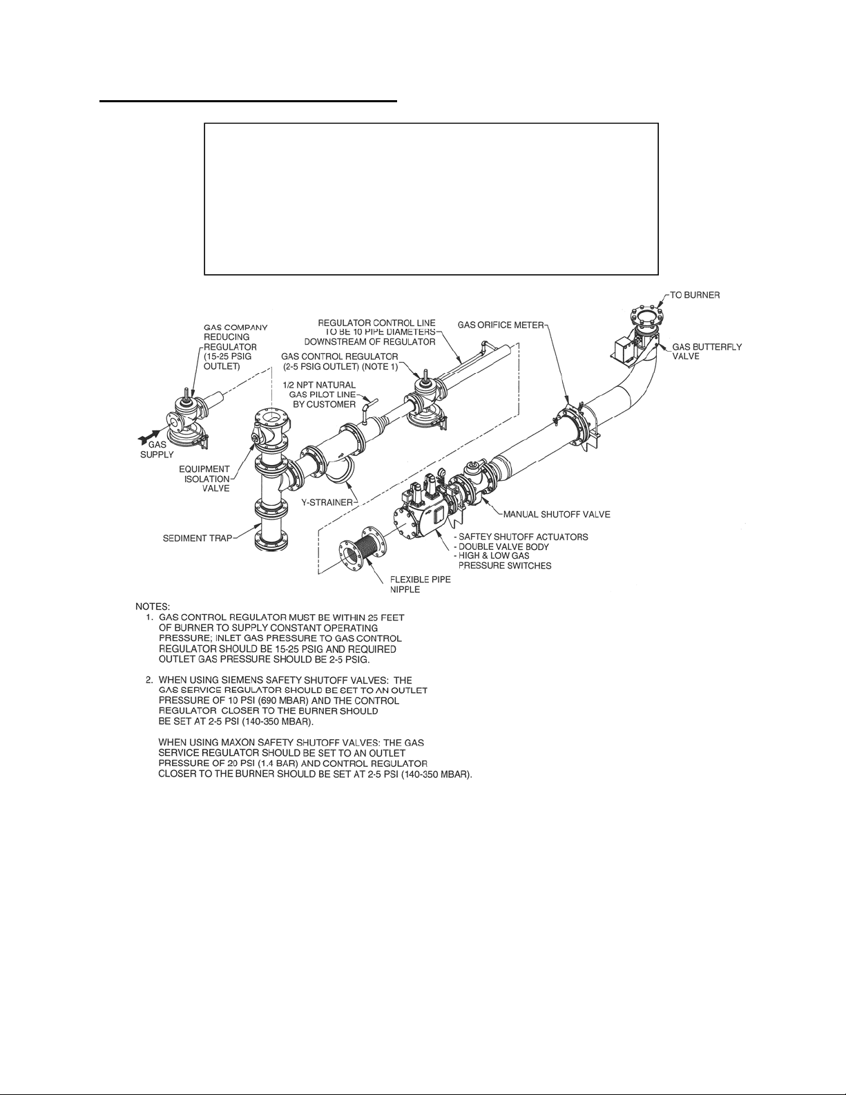
Figure 2. Typical Schematic of Burner Gas Piping
1. Install a controlling gas regulator in the main gas line within 25 ft (7.6m) of the burner. This
regulator should be sized to provide the required gas flow at the inlet of the burner manifold.
Exact gas pressure must be set at the initial start-up depending on piping configuration,
burner size, and maximum capacity desired. Regular settings are designed for best
operation and compliance with NFPA 54 (see Figure 2).
2. A manual equipment isolation valve, sediment trap and gas strainer must be installed
upstream of the gas control regulator to ensure compliance to NFPA requirements. The
manual equipment isolation valve facilitates servicing of the gas control regulator, sediment
trap, strainer, and other components in the gas manifold.
3. The gas company should purge the main gas line to remove scale and dirt before it is
attached to the burner gas manifold.
Page 10
MS-9
4. Connect the main gas line (see Figure 2). A flexible pipe nipple should be used to
connect the gas line to the burner gas manifold (see Table 5 for sizes).
Install a flexible fitting between the gas
manifold and the burner gas connection to
reduce vibration stress on the manifold.
IMPORTANT
MegaStar™ Model No. 50 75-100 125-150
FPN Part No. 800598 800599 800600
Size 3” (DN 80) 4" (DN 100) 6" (DN 150)
Table 5. MegaStar™ Burner Recommended Flexible Pipe Nipples
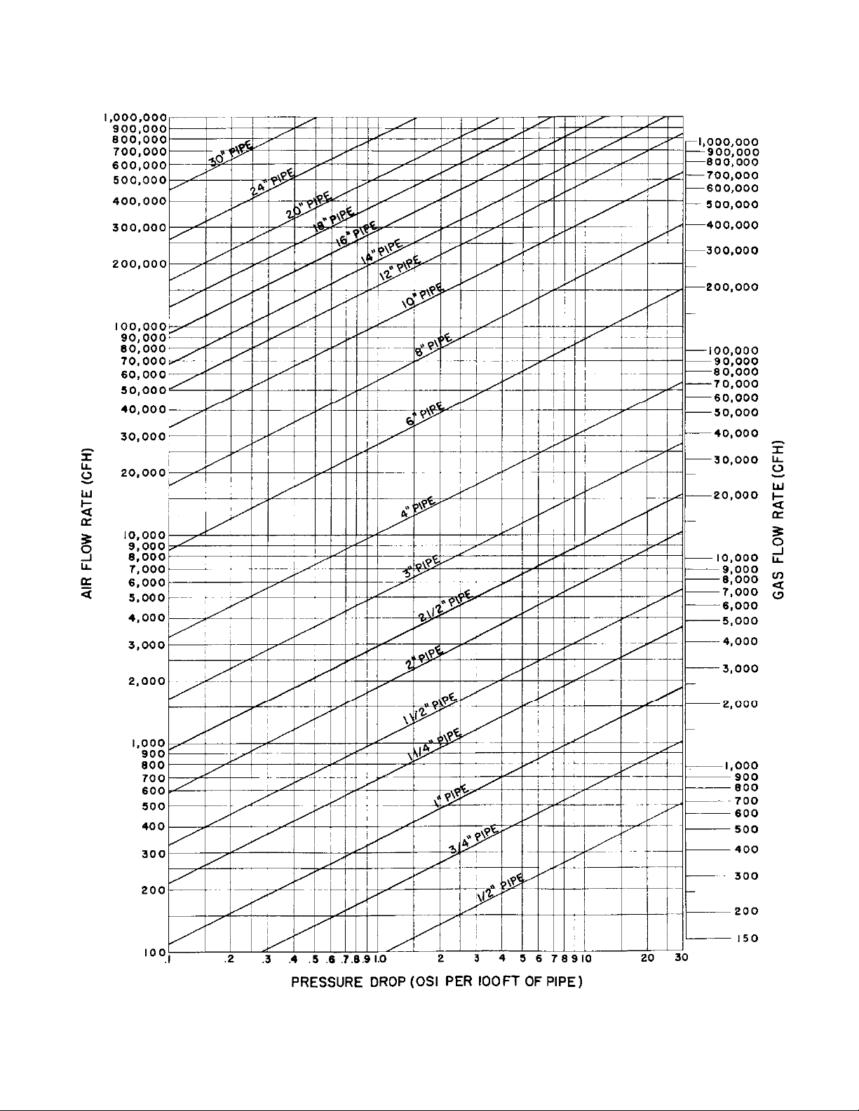
5. The piping from the gas regulator outlet to the burner gas manifold should be sized to
minimize pressure losses. See Figure 3 for pipe pressure losses.
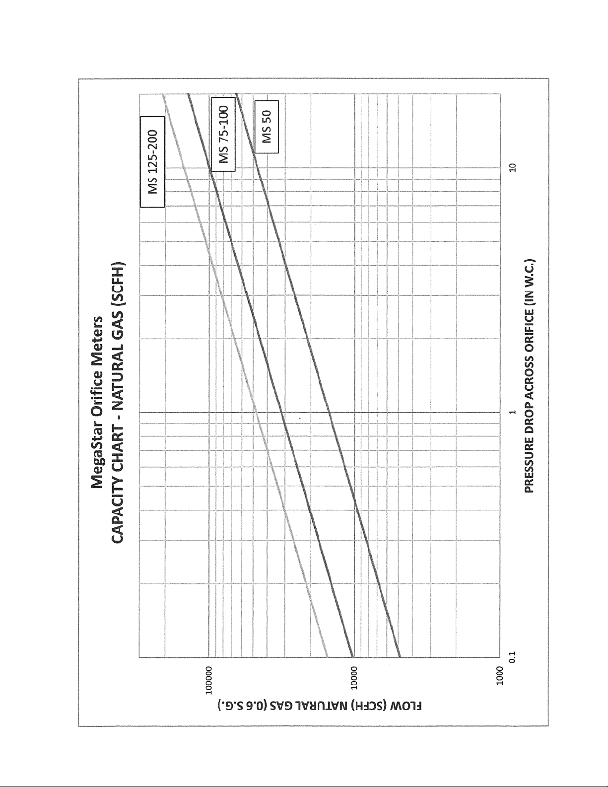
6. The OMG gas orifice meter is an integral part of the gas manifold located on the burner
(refer to Figure 2). Refer to individual burner gas orifice meters graph for gas flows through
the gas orifice meter (see Figure 4). Orifice meter sizes and part numbers are shown below
in Table 6.
Failure to use the gas orifice meter assembly to measure
gas flow will make initial setup and tuning difficult.
IMPORTANT
MegaStar™ Model No. 50 75-100 125-150
OMG Part No. 19816 48242x001 47181x005
Pipe Size 4” (DN 100) 6" (DN 150) 8" (DN 200)
Orifice Size 3.25” (82.5mm) 4.8" (122 mm) 6.0" (152 mm)
Table 6. MegaStar™ Burner Natural Gas Orifice Meter Assemblies
Page 11
MS-9
GL86
Figure 3. Simplified Gas and Air Flow Chart
(@ Atmospheric Conditions)
Page 12
MS-9
Figure 4. MegaStar™ Gas Orifice Meters Graph
Page 13
p
MS-9
J. LIGHT FUEL OIL PIPING SYSTEM
Adjustment of this equipment and its components by
unqualified personnel can result in fire, explosion,
severe
ersonal injury, or even death.
WARNING
Hauck recommends the use of oil manifolds that meet
NFPA guidelines. NFPA requires two safety shutoff
valves piped in series in the burner’s main oil line. A
low/high oil pressure switch must be interlocked with
the burner’s safety shutoff valves. Hauck oil manifolds
have been designed to ensure compliance to NFPA
requirements.
NOTE
1. Hauck recommends using a flexible connection to connect the oil line to the oil manifold
on the burner. A flexible connection will reduce vibration stress on the oil manifold.
Refer to Table 7 for recommended flex connection.
MegaStar™ Model No. 50 75-150
Flex Oil Hose Part No. 11078 20518
Size 1/2" (DN 15) 1" (DN 25)
Table 7. Recommended Flexible Oil Hose Size
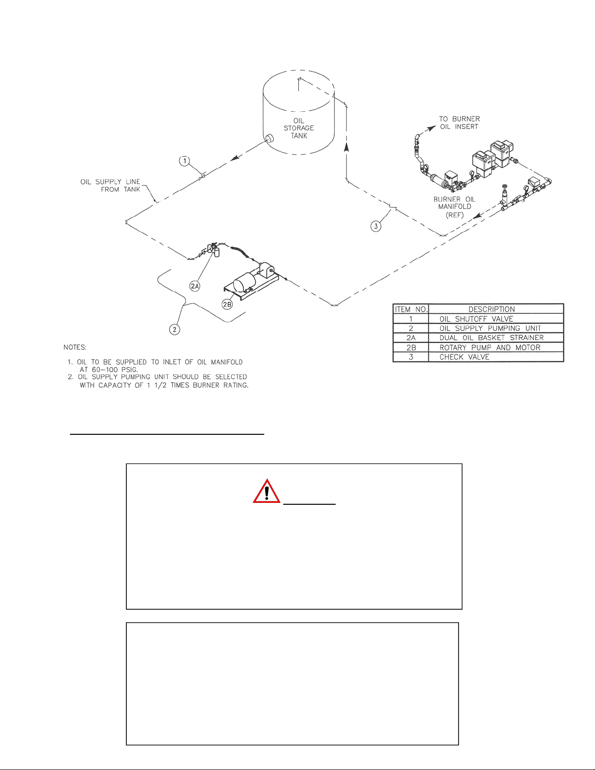
2. For recommended piping sizes see Table 8. Before attaching fuel lines, purge the
piping to remove scale and dirt that could clog and damage oil equipment. Follow Figure 5
for the suggested piping layout.
Discharge Piping, Light Oil
MegaStar
Model No.
50 1"
75 1"
100 1"
125 1"
150 1"
Up to 25'
(Up to
7.6m)
(DN25)
(DN25)
(DN25)
(DN25)
(DN25)
Up to 100 SSU
(Up to 2.1 x 10
25'– 49'
(7.6-
14.9m)
1"
(DN25)
1"
(DN25)
1"
(DN25)
1 ¼"
(DN32)
1 ¼"
(DN32)
-5 m2
/sec)
50' – 100'
(15.2-
30.5m)
1 ¼"
(DN32)
1 ¼"
(DN32)
1 ¼"
(DN32)
1 ½"
(DN40)
1 ½"
(DN40)
Return Piping, Light Oil
Up to 100 SSU
(Up to 2.1 x 10⁻⁵ m2/sec)
Up to 25'
(Up to
7.6m)
1"
(DN25)
1"
(DN25)
1 ¼"
(DN32)
1 ¼"
(DN32)
1 ¼"
(DN32)
25' – 49'
(7.6-
14.9m)
1 ¼"
(DN32)
1 ¼"
(DN32)
1 ¼"
(DN32)
1 ¼"
(DN32)
1 ¼"
(DN32)
50' – 100'
(15.2-
30.5m)
1 ¼"
(DN32)
1 ¼"
(DN32)
1 ¼"
(DN32)
1 ½"
(DN40)
1 ½"
(DN40)
Up to 25'
(Up to
7.6m)
1 ¼"
(DN32)
1 ¼"
(DN32)
1 ¼"
(DN32)
1 ½"
(DN40)
1 ½"
(DN40)
Return Piping
Heavy Oil
25'– 49'
(7.6-
14.9m)
1 ½"
(DN40)
1 ½"
(DN40)
1 ½"
(DN40)
2"
(DN50)
2"
(DN50)
50' – 100'
(15.2-
30.5m)
2"
(DN50)
2"
(DN50)
2"
(DN50)
2"
(DN50)
2"
(DN50)
Table 8. Minimum Pipe Size For Hauck Oil Supply Pumping Units
3. Adjust the bypass relief valve until required oil pressure is achieved. See Table 9 for
approximate settings. Final oil pressure will have to be adjusted to attain desired burner
output and stack exhaust gas analysis.
Page 14
MS-9
MegaStar™
Model No.
50 75 psig (5.15 bar) 90 psig (6.20 bar)
75 75 psig (5.15 bar) 90 psig (6.20 bar)
100 85 psig (5.85 bar) 100 psig (6.90 bar)
125 65 psig (4.50 bar) 90 psig (6.20 bar)
150 80 psig (5.50 bar) 100 psig (6.90 bar)
Nominal Oil Pressure
w/Low Pressure Atomizer
Nominal Oil Pressure
w/Compressed Air Atomizer
Table 9. Nominal Light and Heavy Fuel Oil Pressure to Burner Manifold Inlet
4. The low/high oil pressure switch is factory set at a low set point of 15 psig (1.03 bar)
and a high set point of 80 psig (5.5 bar). Set point adjustments may be required
depending on the burner and fuel piping specifics.
5. Inspect the complete fuel oil system for oil leaks and repair as necessary. Do not
operate the burner until all fuel leaks are repaired.
6. The burner oil flow control (metering) valve is preset to travel from position 2 to 11.
The low fire oil flow setting can be changed by loosening the coupling connecting the oil
valve to the control motor, adjusting the oil valve pointer, and re-tightening the coupling. The
high fire oil flow setting can be changed via the burner control system, or if necessary, by
increasing or decreasing fuel oil pressure. See the individual burner performance sheets for
fuel oil flow data.
Any adjustment to the fuel oil flow settings should be
made as a minor incremental change and verified that it
has not resulted in any detrimental effect to plant
operation prior to making another adjustment.
CAUTION
Fuel oil flow settings per the individual burner
performance sheets are for initial set-up only.
Final settings may have to be readjusted for
required operation.
NOTE
7. Fuel oil flow rates can be checked with the in-line oil flow meter on the burner fuel
oil manifold. The flow meter glass can be rotated to view the scale if required.
Page 15
MS-9
X7864
(NOT TO SCALE)
Figure 5. Typical Schematic of Burner Light Fuel Oil Piping
K. HEAVY FUEL OIL PIPING SYSTEM
Adjustment of this equipment and its components by unqualified
personnel can result in fire, explosion, severe personal injury, or
even death.
Heated fuel oil and piping is hot. Precautions should be taken to
avoid contact with heated oil and piping. Proper insulation should
be installed on hot oil pipes. Protective gloves, clothing and a face
shield are recommended when working with heated oil.
IMPORTANT
For all heavy fuel oil applications, i.e., any oil requiring heating for
use, oil piping must be heat traced (electric or steam) and
insulated. Self-regulating heat tracing is recommended to
maintain the desired temperature of a given fuel oil to achieve 90
SSU (1.8 x 10
-5 m2
/sec) or less at the burner. Electrical heat tracing
with a nominal rating of 12W/ft (39W/m) covered with a nominal 2"
(50mm) fiberglass type insulation is sufficient for most applications.
WARNING

Page 16
MS-9
Hauck recommends the use of oil manifolds that meet NFPA
guidelines. NFPA requires two safety shutoff valves piped in series in
the burner’s main oil line. A low/high oil pressure switch must be
interlocked with the burner’s safety shutoff valves. When preheated oil
is used, a low/high oil temperature limit switch must be interlocked with
the burner’s safety shutoff valves. Hauck oil manifolds have been
designed to ensure compliance to NFPA requirements. Hauck
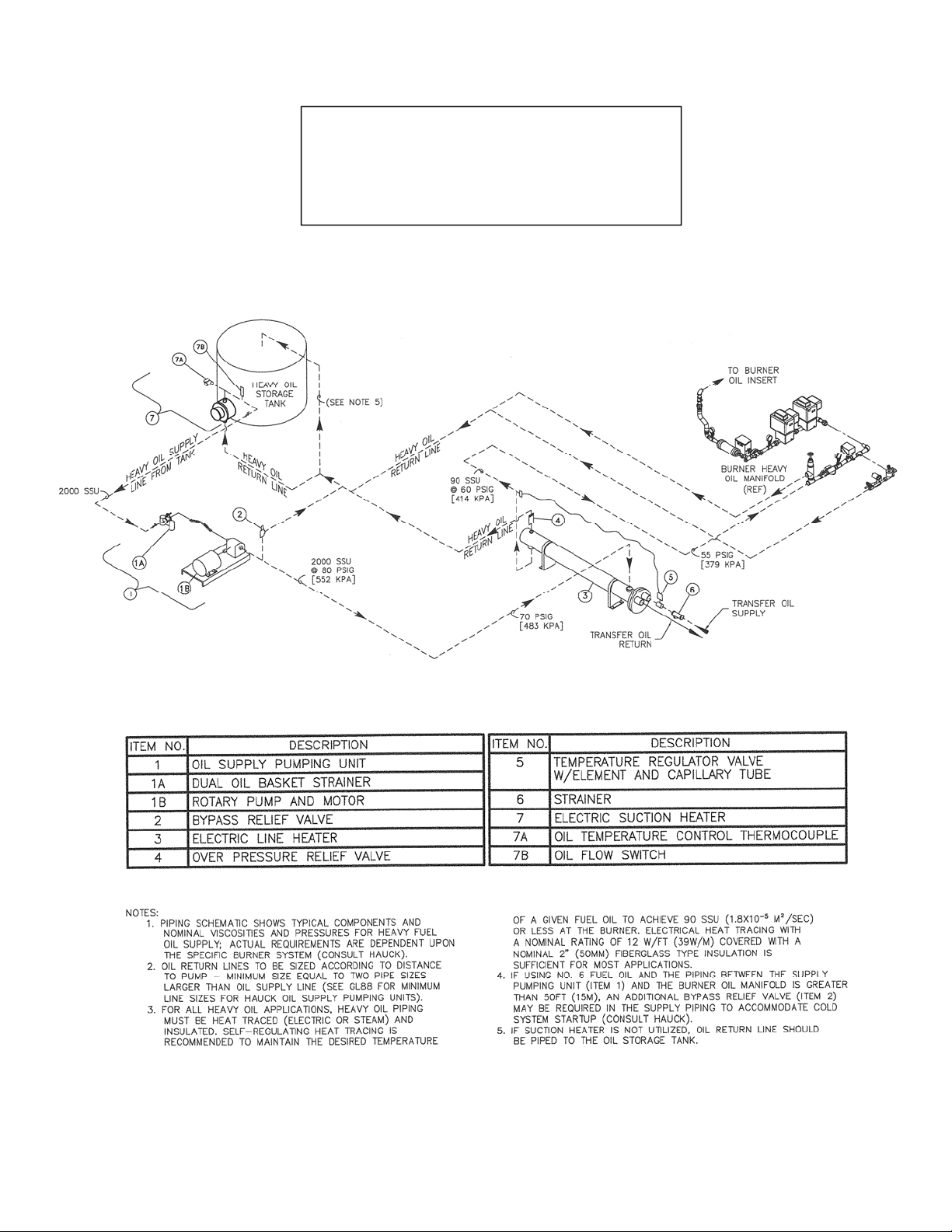
recommends the use of a ‘Heavy Oil Kit’ whenever heavy fuel oil is
used. The components of the heavy oil kit are identified in Figure 6.
NOTE
1. For recommended piping sizes see Table 8. Before attaching fuel lines, purge the piping
to remove scale and dirt that could clog and damage oil equipment. See Figure 6 for the
suggested piping layout.
2. Heavy fuel oil must be 90 SSU (1.8 x 10
-5 m2
/sec) or less for proper atomization and
burning. Use a Hauck viscometer kit (order separately - Part No. 36931) to determine
proper oil temperature to achieve this viscosity. Refer to the instructions that are supplied
with the kit for proper use. In general, the viscosity can be lower than 90 SSU (which
means higher oil temperature) if the fuel is not forming vapor (or steam) pockets in the oil
lines. Vapor pockets can cavitate the pumps used on suction type oil heaters.
3. Set the fuel oil heater temperature set point and the indicating low oil temperature switch
(located on the burner’s oil manifold) to the temperature determined from step 2.
4. Adjust the bypass relief valve until the required oil pressure is achieved. See individual
burner performance sheets for approximate settings. Final oil pressure will have to be
adjusted to attain desired burner output and stack exhaust gas analysis.
5. The low/high oil pressure switch is factory set at a low set point of 15 psig (1.03 bar) and a
high set point of 80 psig (5.5 bar). Set point adjustments may be required depending on
the burner and fuel piping specifics.
6. Inspect the complete fuel oil system for oil leaks and repair as necessary. Do not operate
the burner until all leaks are repaired.
7. The burner oil flow control (metering) valve is preset to travel from position 2 to 11. The low
fire oil flow setting can be changed by loosening the coupling connecting the oil valve to the
control motor, adjusting the oil valve pointer, and re-tightening the coupling. The high fire oil
flow setting can be changed via the burner control system, or if necessary, by increasing or
decreasing fuel oil pressure. See the individual burner performance sheets for fuel oil flow
data.
Any adjustment to the fuel oil flow settings should be
made as a minor incremental change and verified that it
has not resulted in any detrimental effect to plant
operation prior to making another adjustment.
CAUTION
Page 17
MS-9
Fuel oil flow settings per the individual burner
performance sheets are for initial set-up only.
Final settings may have to be readjusted for
required operation.
NOTE
8. Fuel oil flow rates can be checked with the in-line oil flow meter on the burner fuel oil
manifold. The flow meter glass can be rotated to view the scale if required.
X7872
(NOT TO SCALE)
Figure 6. Typical Schematic of Burner Heavy Fuel Oil Piping

Page 18
MS-9
L. OIL MANIFOLD HEAT TRACING
For heavy, waste, or recycled oil applications, the oil manifold piping must be heat traced and
insulated to maintain the desired temperature, and hence, viscosity, of the fuel oil (see Figure
7). The Hauck heat tracing kit installed on the heavy oil manifold will aid in viscosity control and
reliable main flame ignition of the burner. The oil manifold heat tracing kit consists of heat
tracing cable which is wrapped around all piping, and covered with fiberglass insulation and
jacketing.
X8046
(NOT TO SCALE)
Figure 7. Heavy Oil Manifold Heat Tracing Kit
120V/60Hz power for the oil manifold heat tracing kit
must be supplied separately by the customer and wired
into the heat tracing power connection box.
NOTE
The heat tracing cable is self-regulating with a nominal rating of 12 W/ft (39 W/m). When the
circuit breaker switch to the oil manifold heat tracing kit is energized, the self-regulating heat
tracing will automatically switch on and off based on heat demand.
M. HEAVY OIL INSERT HEATER
Heavy, waste, or recycled fuel oils require some means of viscosity control. The Hauck heavy
oil insert heater installed in the burner’s oil tube (see Figure 8) is a perfect solution to the
viscosity control problem and reliable main flame ignition of the burner at cold temperatures.
The heavy oil insert heating element, in conjunction with the oil temperature indicating
controller, will maintain an optimum oil temperature in the oil tube to ensure a reliable burner
main flame ignition after an extended shutdown of the burner.

Page 19
MS-9
V7867
(NOT TO SCALE)
Figure 8. Heavy Oil Insert Heater
120V/60Hz power for the heavy oil insert heater
must be supplied separately by the customer
and wired into the heater junction box.
NOTE
Operation of the heavy oil insert kit is as follows (see Figure 8):
1. Adjust the low oil temperature controller to the desired temperature as determined in Section
K from testing of the heavy fuel oil viscosity.
Adjusting the trip setpoint above the required temperature, as
determined by fuel oil viscosity testing, may result in coking of
the fuel oil in the oil insert assembly piping.
NOTE
2. Energize the insert heater circuit breaker switch.
3. When the oil temperature exceeds the setpoint on the oil temperature indicating controller,
the oil temperature indicating controller switch contact will open and power to the heater
element is removed.
4. When the oil temperature drops below the setpoint on the oil temperature indicating
controller, the oil temperature indicating controller switch contact will close and the heater
element will energize.
See ESII-9.2 Heavy Oil Insert Heater Kit Instructions for more specific detail on the operation
and maintenance of the heavy oil insert heater.
Page 20
MS-9
N. FUEL OIL NOZZLE
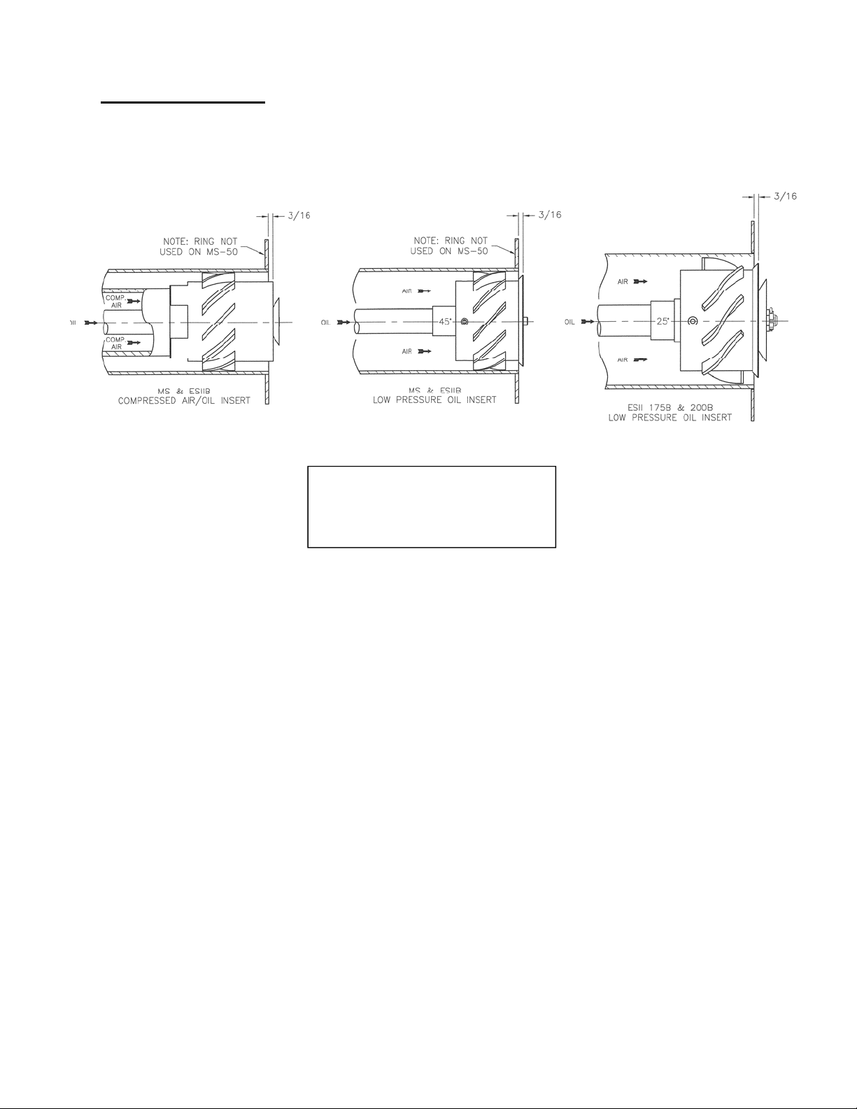
The position of the fuel oil atomizer affects its ability to atomize the oil. The compressed air
atomizer or low pressure atomizer should be positioned as shown in Figure 9.
Ensure that the correct atomizer
is being used when firing oil.
Figure 9. Oil Nozzle Position
CAUTION
W7868
(NOT TO SCALE)
To change the low pressure oil nozzle position:
1. Shut off the manual oil valve at the burner. The burner must not be firing and the atomizing
air fan must be shut off.
2. If heated heavy oil is being used, allow the oil in the pipe to cool to avoid burns. Drain
residual fuel into an appropriate container.
3. Note the present orientation of the oil nozzle in the burner. Determine if the oil nozzle must
be retracted into or extended out of the primary air tube (see Figure 9).
4. Remove the bolts securing the backplate to the burner, and disconnect the pilot air pipe.
5. Loosen the jam nut on the backplate of the burner oil insert assembly.
6. Rotate the backplate to effect the required retraction or extension of the oil atomizer nozzle.
One full rotation of the backplate will move the atomizer approximately 0.1" (2.5mm).
7. Once the proper positioning of the atomizer is completed:
a. Tighten the jam nut.
b. Attach the burner oil insert assembly to the oil manifold, using the union provided.
c. Open the manual oil valve and check for leaks using accepted practices.

Page 21
MS-9
O. COMPRESSED AIR/OIL ATOMIZER
The Hauck high pressure oil nozzle is designed to finely atomize No. 2 fuel oil and clean
preheated No. 4, No. 5 and No. 6 fuel oil. Oil viscosity should be 90 SSU (1.8 x 10
-5 m2
/sec) or
less. Preheat fuel oil and heat trace piping using No. 4, No. 5 and No. 6 fuel oil to achieve 90
SSU oil at the burner (see Compressed Air/Oil Adjustment).
Care should be taken to insure that the air and oil supplied to the burner are free of dirt particles
and water. Purge oil and air lines before connecting them to the compressed air/oil insert. The
nozzle should be inspected and cleaned before the start of each session and possibly more
depending on the cleanliness of the air and fuel.
COMPRESSED AIR PIPING
1. The compressed air supply line must be of adequate size (see Table 10) and be a dedicated
line from the compressor to the burner compressed air inlet. For longer runs than those listed
in the table, increase the hose by one pipe size. Before attaching lines, purge the hose to
remove any dirt that could clog and damage the oil atomizer.
MegaStar
Model No.
TM
Min. Hose
Size
Max. Hose
Length
75-100 3/4 NPT (DN20) 70 ft (21m)
125-150 1 NPT (DN25) 160 ft (49m)
Table 10. Flexible Air Hose Size Requirements
2. Compressed air requirements are listed in Table 11. Compressed air must be supplied to
the inlet of the compressed air manifold at a minimum of 90 psig (620 kPa). The
compressed air regulator modulates the compressed air flow as oil flow is modulated to
reduce compressed air consumption at lower firing rates.
The compressed air low supply pressure switch and low
atomizing pressure switch must both be interlocked with
the burner’s oil safety shutoff valves.
The compressed air solenoid valve is normally wired in
parallel with the burner’s safety shutoff valves.
Reference the control panel drawings for wire and/or
terminal numbers.
NOTE

Page 22
MS-9
MegaStar
Model No.
75/100
Air Flow
TM
Oil Flow
Oil Pressure
To Burner
Nozzle
Compressed
(gpm) (lpm) (psig) (kPa) (scfm) (nm3/min) (psig) (kPa)
12 45.4 60 414 60 1.6 55 379
9 34.1 50 345 52 1.4 44 303
Compressed
Air Pressure
To Burner
Nozzle
6 22.7 38 262 48 1.3 32 221
1.25 4.7 24 165 42 1.1 17 117
125/150
18 68.1 60 414 90 2.4 50 345
10 37.9 36 248 85 2.3 30 207
5 18.9 23 159 82 2.2 20 138
3 11.4 20 138 80 2.1 19 131
Table 11. Compressed Air and Oil Requirements
3. When firing the burner with the compressed air atomizer, the threaded pipe plug must be
removed from the primary air tube. If using the low pressure oil or liquid propane nozzles,
the pipe plug must be installed in the primary air tube. When firing natural gas the pipe
plug can be installed or removed. The pipe plug is accessible through the main fan
housing access door (see Figure 11).
COMPRESSED AIR/OIL ADJUSTMENT
1. Air and fuel flows and pressures can be observed at the burner using the compressed air
and fuel flow meters and corresponding pressure gauges (see Figure 10). For compressed
air data in addition to Table 11, see individual MegaStar
TM
capacity and performance sheets.
2. Compressed air supply pressure to the inlet of the compressed air manifold must be 90 psig
(620 kPa) or greater. The supply pressure is measured via the gauge on the inlet to the
compressed air flow meter (see Figure 10). The compressed air low supply pressure switch
is preset at 60 psig (414 kPa). Set point adjustment may be required depending on the
burner and compressed air piping specifics.
3. For the compressed air manifold with regulator to function properly, the impulse line and
upper chamber of the pressure reducing regulator must be loaded with oil by opening the
vent valve on the regulator until oil vents then closing the vent valve.
4. Final compressed air flow and pressure adjustment is made via the compressed air trim
valve (see Figure 10). With the burner at high fire, adjust the trim valve until the compressed
air burner inlet pressure gauge, located downstream of the trim valve, reads approximately
60 psig (414 kPa). The compressed air low atomizing air switch is preset at 5 psig
(34.5 kPa). Set point adjustment may be required depending on the burner and compressed
air piping specifics.
5. Compressed air flow can be read directly from the compressed air flow meter
(see Figure 10). Refer to Figure 12 for detailed instructions on how to head the compressed
air flow meter. Verify that both the compressed air flow and burner inlet pressure, from step
4, meet or exceed the values given in Table 11 and/or the additional burner capacity and
performance data sheets.

Page 23
MS-9
For all heavy fuel oil applications, i.e., any oil requiring heating for
use, oil piping must be heat traced (electric or steam) and
insulated. Self-regulating heat tracing is recommended to
maintain the desired temperature of a given fuel oil to achieve 90
SSU (1.8 x 10
-5 m2
/sec) or less at the burner. Electrical heat tracing
with a nominal rating of 12W/ft (39W/m) covered with a nominal 2"
(50mm) fiberglass type insulation is sufficient for most applications.
IMPORTANT
Y7041
(NOT TO SCALE)
Figure 10. Compressed Air Manifold Detail

Page 24
MS-9
W7084
(NOT TO SCALE)
Figure 11. Primary Air Tube Pipe Plug Location
COMPRESSED AIR FLOW METER
The compressed air flow meter is offered with a standard multi-pressure flow scale.
The multi-pressure flow scale has a vertically graduated scale, calibrated for air in standard
cubic feet per minute (scfm) at 1.0 s.g. (70°F at 100 psig), or liters per second (lps) at 1.0 s.g.
(21°C at 6.9 bar). The multi-pressure scale design allows for use at supply pressures from 40 130 psig in 10 psig increments (3.0 - 9.0 bar in 1 bar increments) .
To determine the compressed air flow rate, refer to Figure 12 and proceed as follows:
1. Read the inlet pressure on the pressure gauge of the compressed air flow meter.
2. Select the appropriate inlet pressure (psig) vertical line, or interpolated value closest to the
gauge reading, and follow the line upward until it intersects the brightly colored horizontal
indicator bar.
3. From the intersecting point on the horizontal indicator bar, follow the slope as shown on
the diagonal lines to the 100 psig inlet pressure vertical line and interpolate the scfm or
lps flow rate (Note for the example shown in Figure 12, with an inlet pressure of 60 psig,
the compressed air flow rate is approximately 40 scfm).

Page 25
MS-9
Figure 12. Compressed Air Flow Meter and Scale
To change the compressed air/oil nozzle position.
1. Ensure that the burner is not firing, then close the manual oil valve and the manual
compressed air ball valve at the burner. The burner must not be firing
2. If heated heavy oil is being used, allow the oil in the pipe to cool to avoid burns. Drain
residual fuel into an appropriate container.
3. Note the present orientation of the air/oil nozzle in the burner. Determine if the air/oil
nozzle must be retracted into or extended out of the primary air tube (see Figure 9).
4. Loosen the two set screws on the backplate lock collar of the air/oil insert assembly.
5. Slide the insert assembly to effect the required retraction or extension of the air/oil nozzle.
6. Once the proper positioning of the air/oil nozzle is completed:
a. Tighten the two setscrews in the backplate lock collar.
b. Attach the air/oil insert assembly to the oil manifold, using the union provided.
c. Open the manual oil valve. Check for leaks using accepted leak check practices.

Page 26
MS-9
P. LIQUID PROPANE (LP) FUEL PIPING SYSTEM
WARNING
Adjustment of this equipment and its components by unqualified personnel can
result in fire, explosion, severe personal injury, or even death.
LP is highly flammable and heavier than air. It will accumulate near the ground in
the area of a leak and will dissipate relatively slowly. LP or Butane in its liquid state
can cause freezing and severe injury.
Hauck does not recommend installation of a line-reducing regulator in the LP
supply line. If the regulator diaphragm were to total system pressure would be
applied to the burner and could result in damage to equipment, including the
baghouse, and result in serious injury to personnel.
Hauck recommends the use of LP manifolds that meet NFPA guidelines. NFPA
requires two safety shutoff valves piped in series in the burner's main LP line. A
low/high pressure LP switch must be interlocked with the burner's safety shutoff
valves. Hauck's LP manifolds have been designed to ensure compliance to NFPA
requirements. All piping must be installed in compliance with applicable piping
codes and regulations. Equipment must meet the ratings for service as indicated in
NFPA 58.
NOTE
1. LP or butane is supplied to the MegaStar™ burner in a liquid form and is vaporized as the
fuel exits the burner nozzles.
2. Hauck recommends using a flexible connection to connect the LP line to the burner. A
flexible connection will reduce vibration stress on the LP connection. Refer to Table 12 for
recommended flex connection. Follow Figure 13 for the suggested piping layout.
MegaStar™ Model No. 50 75-100 125-150
Flexible LP Hose Part No. 45754 45755 47533
Size 3/4" NPT (DN15) 1" (DN25) 1¼" (DN32)
Table 12. Recommended LP Flexible Hose Size
3. Before attaching LP fuel lines, purge the lines with compressed air. Then, leak test piping
with compressed air.
4. Connect the main LP line at the appropriate connection on the burner skid. The capacity of
the LP fuel system should be 1.5 times the rated capacity of the burner.
5. If Hauck has supplied the LP pump set for this application, consult the pump installation
instructions for information on the unit.
If the burner is being converted from natural gas or oil to LP firing, the diverter ring
located on the end of the primary air tube assembly must be removed (consult
Hauck for details). Also, the LP nozzle must be removed prior to converting the
burner to natural gas firing to avoid damage to the LP nozzle.
NOTE

Page 27
MS-9
Figure 13. Typical Schematic of LP Piping
NOTE
The LP piping system shown in Figure 13 is designed for optimum
performance at ambient air temperatures above 40
ambient temperatures below 40
Hauck strongly recommends that a bypass flow control valve and a
backpressure regulator be installed in all LP systems and piped as shown in
Figure 13.
o
F, consult Hauck for recommendations.
CAUTION
o
F (5°C). For operation in
6. After completing piping, check all LP lines and connections for leaks following accepted
standards and practices. Do not operate the system until all leaks are repaired.
X7869
(NOT TO SCALE)

Page 28
MS-9
7. Adjustment of LP supply pressure: (see Table 13 for recommended settings).
a. Install an amp probe on the LP pump power supply line.
b. Close the ball valve between the back pressure regulator and the tank to temporarily
take the regulator out of the system (see Figure 13).
c. The bypass flow control valve is used as a system safety. Normally set at 50 psig
(345 kPa) above the maximum expected tank pressure, it operates only in the case of
a back pressure regulator failure.
d. Adjust the bypass flow control valve to the following initial settings:
100% Commercial Propane 235 psig (16.20 bar)
50/50 Propane/Butane 170 psig (11.70 bar)
100% Butane 95 psig (6.55 bar)
e. The back pressure regulator functions as the primary control in setting the LP supply
pressure to the burner. To adjust the back pressure regulator, open the ball valve
between of the back pressure regulator and the tank, and adjust the regulator to an
initial setting of 25 psig (172 kPa) below the flow control valve setting.
f. Adjust the back pressure regulator to the following initial settings:
100% Butane 70 psig (4.80 bar)
If pump motor nameplate amperage is exceeded, reduce
pressure in Step 7.d to below nameplate amp rating.
Frost or icing is an indication of an LP leak. It is
possible for a leak to occur without such evidence.
Although the LP supply is initially in a liquid state, as it
is vaporized it becomes heavier than air and
accumulates near the ground and dissipates relatively
slowly, becoming highly flammable. Extreme care
should be exercised with LP fuels and systems.
Do not exceed the minimum LP pump motor nameplate
amp load at any time while making adjustments.
100% Commercial Propane 210 psig (14.50 bar)
50/50 Propane/Butane 145 psig (10.00 bar)
WARNING
CAUTION
NOTE

Page 29
MS-9
g. The low/high LP pressure switch is factory set at a low set point of 165 psig (1140 kPa)
and a high set point of 230 psig (15.9 bar). The low pressure switch setting should be
approximately 15 psig (1.03 bar) below the back pressure regulator setting.
h. Check with your LP supplier for the exact maximum expected tank pressure for your fuel.
8. The burner LP flow control (metering) valve is preset based on flow required from low to
high fire. The low fire LP setting can be changed by loosening the coupling connecting the
LP valve to the control motor, adjusting the LP valve pointer, and re-tightening the coupling.
The high fire LP flow can be changed via the burner control system, or if necessary , by
increasing or decreasing LP pressure. See the individual burner performance sheets for LP
fuel flow data and settings. If the burner LP fuel control valve continually freezes at low fire,
increases LP flow slightly until freezing stops. If the burner LP nozzle continually freezes it
usually indicates that water is in the fuel. Contact your LP fuel supplier about the addition of
methanol to your LP fuel tank.
Any adjustment to the LP fuel flow settings should be
made as a minor incremental change and verified that it
has not resulted in any detrimental effect to plant
operation prior to making another adjustment.
CAUTION
LP fuel flow settings per the individual burner
performance sheets are for initial set-up only.
Final settings may have to be readjusted for
required operation.
NOTE
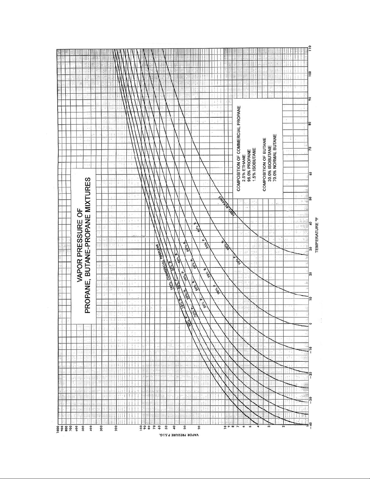
9. Different size nozzle holes are required on propane, butane, or mixtures of both to assure
optimum vaporization and combustion. If using a butane or propane / butane mixture, be
sure to specify the fuel when ordering and consult Hauck for specific nozzle hole sizes.
10. The MegaStar
TM
utilizes a multi-port LP nozzle assembly positioned around the primary air
tube. Atomizing air supplied from an auxiliary blower assists in mixing and vaporizing the
propane. The nozzle assembly incorporates a series of holes and nozzles to control the LP
flow. Check for plugged nozzle holes by removing the nozzle from the burner and running
water through it to make sure all the holes are clear. Clean any blocked holes and return
the nozzle to its original position.
Max. Tank Temp.
(°F) (°C) (psig) (bar) (psig) (bar) (psig) (bar)
70 21 175 12.10 125 860 75 520
80 27 190 13.10 140 965 80 550
90 32 215 14.80 160 1,100 85 585
100 38 230 15.90 170 1,170 95 655
100% Propane
50% Propane
50% Butane
100% Butane
Table 13. Recommended Burner Supply Fuel Pressures
Page 30
MS-9
Figure 14. Vapor Pressures of Propane, Butane and Butane-Propane Mixtures

Page 31
MS-9
Q. LIQUID PROPANE (LP) NOZZLE
To install the liquid propane (LP) nozzle, it is necessary to work on both the front and rear of the
burner. All necessary safety procedures should be followed to ensure that work can be
performed on both ends of the burner. The LP nozzle will appear different depending on the
operating capacity of the burner, see figure 15 for details. The following procedure should be
followed when installing the LP nozzle.
1. Check the primary tube for a choke ring (Figure 16). If the choke ring is present, it must be
removed to accept the LP nozzle.
2. Remove the access door from the rear of the burner air housing. Verify that a 2" NPT pipe
plug is installed in the primary air tube. (see Figure 17)
3. Loosen the lock nut and insert backplate from the LP insert.
4. From the front end of the burner, insert the nozzle and feed piping from the primary tube.
5. When properly installed, LP nozzle rests against the secondary air tube (Figure 16). NOTE:
On the ESII175B and ESII200B, the primary tube will contact a stop in the nozzle.
6. Align the nozzle as shown in Figure 16. Tighten setscrews on the nozzle and reinstall the
insert backplate and lock nut.
W9048
(NOT TO SCALE)
Figure 15. LP Nozzle Orientation

Page 32
MS-9
W9048
(NOT TO SCALE)
Figure 16. Burner Front End
W9048
(NOT TO SCALE)
Figure 17. LP Insert

Page 33
MS-9
R. BURNER PILOT SYSTEM
The MegaStar™ incorporates a gas pilot with induced air (see Figure 18). The pilot is detected
by the main burner UV scanner which is factory mounted and wired. The pilot is properly
installed as delivered and should not need to be moved or adjusted. Note, UV scanner is
shipped loose.
1. Before connecting to the pilot assembly gas line, the gas line should be purged to remove
any dirt. Pipe the pilot gas supply line to the inlet of the pilot gas shutoff valve and check for
leaks. Size the pilot gas supply line to avoid excessive pressure drops. For pilot gas
supply lines up to 25 ft (7.6m), use 1/2 NPT (DN 15) or larger piping.
2.
Constant gas pressures ranging from 15 psig (1.03 bar) minimum to 25 psig (1.72 bar)
maximum must be available at the inlet of the Hauck gas pilot manifold. Pilot capacity
should not exceed 150,000 Btu/hr (44kW).
3. The spark wire gap is factory set at 1/8" (3mm). This gap can be changed by carefully
removing the pilot internals. Bend the spark wire to adjust, reinsert, and check the gap.
For field adjustment, a U.S. 5¢ coin with 0.08" (2mm) thickness can be used as a
gauge for adjusting the spark gap.
W9003
(NOT TO SCALE)
Figure 18. Pilot Manifold Detail
4. Complete the initial pilot adjustment of the air shutter as follows (see Figure 18):
a. Loosen, but do not remove, the locking thumbscrew.
b. Adjust the air shutter to approximately 1/4" (6.4mm) gap opening.
c. Securely tighten the locking thumbscrew.
d. Slowly open the gas flow valve and light the pilot by means of electric ignition.
The pilot ignition transformer can cause an electric shock - use care around
the ignition cable. When test firing the pilot, leave pilot gas on briefly. If pilot
does not light quickly, shut it off and repurge before attempting to relight.
CAUTION

Page 34
MS-9
S. PRIMARY AIR
Primary air is used for improved mixing at low fire on LP fuel, and for the optional low pressure
atomization of oil fuel. Hauck offers a TBA blower for primary air supply. The primary air blower
is supplied with an outlet flange to mate to the air connection on the burner. Piping between the
blower and the burner is not supplied with the burner. Once installed, verify that no air leaks
exist between the blower and the burner. If leaks exist, burner efficiency will be reduced.
T. BURNER SETUP
Adjustment of this equipment by unqualified personnel
can result in fire, explosion, severe personal injury, or
even death.
WARNING
These settings are for initial setup only. Final settings will have
to be readjusted for required operating conditions.
NOTE
Use of individual control motors allows the fuel valves to be characterized via the BCS6000
control panel to maintain a tighter air/fuel ratio over the entire burner operating range. Starting
points for fuel control valves are shown in Figure 19 and in the individual burner capacity and
performance data sheets. Final settings of the fuel valves can then be set at multiple control
points using the BCS6000 control panel.
Nominal Settings (see Figure 19)
1. All control motors have a travel of 90°.
2. The low fire starting frequency for the combustion air blower is 16Hz. Always be sure that
the combustion air blower is operating at 16Hz prior to pilot and main flame ignition. During
operation, the blower frequency will need to modulate between 16 and 60Hz as required to
maintain process temperature.
3. Natural Gas Valve. Low fire is adjusted at the main gas valve. Adjust using the gas
metering orifice (see Orifice Meter Capacity Chart in Figure 4). The natural gas valve has a
nominal travel from the off position (low fire) to 9 (high fire) on the valve position indicator
dial plate.
4. Oil Metering Valve . The valve has a nominal travel from position 2 to 11 (see capacity and
performance data sheets).

Page 35
MS-9
5. Propane Metering Valve. Low fire is adjusted at the main LP fuel valve. Adjust while
watching the LP fuel flow meter. If freezing occurs, open the low fire setting ¼ of a position
at a time until the freezing stops. The valve travel varies for a given burner model
(see individual burner capacity and performance data sheets).
X7870
(NOT TO SCALE)
Figure 19. Individual Control Motor Settings
U. OPERATION
Adjustment of this equipment by unqualified personnel can result in fire,
explosion, severe personal injury, or even death.
WARNING
1. The MegaStarTM uses individual control motors directly coupled for each fuel control valve.
The optional remote rack mounted fuel manifold includes a separate control motor for the
fuel control valves, which is electronically linked to the air control. Air control is performed
with a VFD, modulating the output frequency between 16 Hz and 60 Hz to achieve a precise
air flow.

Page 36
MS-9
2. The combustion air must cycle to 60 Hz for purging the system before light off, the safety
limits must be satisfied, and the purge air pressure switch must be made for the purge to
begin. The plant exhaust fan must be running with its damper open sufficiently for the
proper purge time. The minimum purge time is the time required for four volumes of air to
flow through the entire combustion and exhaust system (including the baghouse and flue
stack). For most applications, the combustion air blower will modulate from 16Hz at low fire
to 60Hz at high fire.
3. Set the low gas pressure switch to an initial setting of 0.5 psig (3.4 kPa).
4. Set the high gas pressure switch to an initial setting of 5 psig (34.5 kPa).
5. The fuel valve must be adjusted for proper flow control. See individual burner performance
sheets for fuel flows. Adjustment can be electronically performed with bias points
characterizing the valve position, or it can be set manually so that the closed position
provides the correct flow rate for low fire.
6. Before light off, the combustion air blower must be running at 16Hz; the contacts in the
combustion air switch must be set to close at 1" wc (25 mm wc). The low fire fuel limit
switches, located on the fuel manifold, must be set to have closed contacts when the fuel
valve is at low fire. Do not attempt to ignite the burner unless it is at low fire.
V. ADJUSTMENTS
1. In order to drive each control motor, consult burner control panel instructions.
2. The spin vane adjustment affects the flame shape and combustion intensity. Spin set at 0°
will produce a long narrow flame; a spin setting of 50° will produce a short wide flame (see
individual burner capacity and performance data sheets). For most applications, the spin
should be set in the mid range (30° - 45° on indicator). For a very short flame, in a large
diameter combustion zone, the spin can be set on maximum (50° on indicator). Caution
is advised as overheating of the combustion flights or drum could occur when using
maximum spin. When adjusting the spin to less than 30° for a long flame, check the exhaust
gas to make sure the flame is not too long that it extends into the veiling zone of the dryer
(this can lead to incomplete combustion resulting in high CO and unburned hydrocarbon
emissions in the flue gas).
The MegaStarTM Burner flame is very intense. It is designed to burn quickly and
completely in the recommended combustion space. Flame adjustments on new
installations should be started with a narrow flame (30°) spin setting. Drum
temperatures should be checked using a hand held non-contact infra-red
thermometer particularly in the combustion zone area. The flame shape can then
be widened while observing drum temperature in the combustion zone.
WARNING
3. During the adjustment process take exhaust gas measurements to verify that complete
combustion is taking place (see Application Sheet GJ73 for general information on
conducting exhaust gas analysis).

Page 37
MS-9
W. MAINTENANCE
The Hauck MegaStarTM burner has minimal internal moving parts and is relatively maintenance
free. However, there are a few items that should be periodically checked.
1. Check the fuel control valves for proper operation.
2. For burners fired on oil:
Dirt can clog the atomizing air nozzle, as well as cause problems firing the burner. If the
nozzle is dirty, fuel oil will not atomize properly and will result in lower combustion efficiency.
Twice a year (or more frequently when firing heavy fuel oil, waste oil or in dusty conditions),
remove and clean the burner oil insert tube and nozzle assembly as described below:
a. Shut off the oil flow to the burner.
b. Note the relative location of the oil atomization nozzle with respect to the primary air
tube.
c. Remove the bolts that secure the atomizing air backplate and remove the backplate
and its attached fuel tube and atomizing oil nozzle.
d. Disassemble the nozzle. Clean all the components of oil and other foreign material
that may be plugging the nozzle holes. If used on heavy fuel oil, remove the nozzle
and soak it in a solvent to loosen the oil deposits. Scrape the nozzle body and holes
(if necessary) using wooden tools or a plastic bristle brush only, being careful
not to damage machined parts.
e. Reassemble the oil nozzle, reattach the nozzle to primary air tube, and then attach the
burner backplate to the burner body.
f. Check to ensure that the atomizing oil nozzle is at the proper position inside the
burner (see Section N).
3. Periodically check all safety equipment, such as pressure switches, solenoid valves, and
safety shutoff valves to ensure they are not clogged with dirt, or in any way inoperative.
4. Check and clean UV scanner lens as conditions dictate to keep it clean of dirt and dust.
If the fan motor or impeller are removed or replaced, the
fan vibration should be checked upon reassembly. If
vibration levels are excessive, the fan should be trim
balanced to minimize motor bearing wear.
NOTE
5. A yearly check of the fan (impeller/motor) vibration, measured in the vertical direction at the
motor bearings, is recommended. Consult Hauck for acceptable vibration levels.
6. MegaStar
TM
fan impellers are equipped with wear resistant impeller blades. However, every
effort should be made to minimize dust entering into the fan impeller. Excessive dust may
cause premature wearing of impeller blades and burner parts in addition to unbalance of the
fan.
7. Should it be necessary to remove the fan impeller from the motor shaft, it is important to
replace the fan impeller in the proper position. See Figure 20 for installation instructions.
If the fan wheel is not installed properly, air capacity
of the main fan will be reduced, diminishing burner
capacity and efficiency.
IMPORTANT

Page 38
MS-9
8. Periodically check air/fuel ratio to ensure that the burner is operating at peak efficiency.
Exhaust gas analysis can be performed with most commercially available gas analyzers.
Y7871
(NOT TO SCALE)
Figure 20. Proper Impeller Position On Motor Shaft
X. RECOMMENDED SPARE PARTS
ITEM QTY. PART NO. DESCRIPTION
1 1 20627 Control Motor, Air, High Torque
1A 1 62960 Control Motor, Fuel, Medium Torque
2 1 20579 UV Scanner
3 2 84447812 Air Pressure Switch, Combustion Air & Purge Air,
1 - 20" wc (25-508mm wc) (LP & Low Pressure Oil Only)
4 1 84447832 Air Pressure Switch, Primary Air, 12-60"wc (405-1520mm wc)
5 1 61020 Air Pressure Switch, Compressed Air, 30 psig (207 kPa)
Table 14. Recommended Spare Parts

Page 39
MS-9
APPENDIX:

Page 40
MS-9
APPENDIX:

Page 41
MS-9
APPENDIX:

Page 42
MS-9
APPENDIX:

Page 43
MS-9
APPENDIX:
Page 44
MS-9
APPENDIX:

Page 45
MS-9
APPENDIX:

Page 46
MS-9
APPENDIX:

DRYER DRUM GAS ANALYSIS
HAUCK MANUFACTURING CO.,
FOR NATURAL GAS, OIL AND LP
Gas analyses are used to indicate the air/fuel ratio and to indicate the degree of completeness
of combustion. If the mixing is poor, an excess of air must be supplied so that every particle of
fuel will contact some air and burn. Unburned fuel is simply wasted since it does not contribute
heat to the process.
A critical step in every dryer drum gas analysis is the placement of the sample tube. The applicability of the readings depends directly on the location from which the sample is drawn. To give
you an idea of the recommended placement, we have included a drawing in this section. Refer
to “Typical Sample Tube Installation for Dryer Drum Gas Analysis”.
The procedures used to make an accurate gas analysis vary not only with the method employed
but also with the manufacturer of the equipment. In most instances good readings require that
the manufacturers instructions be adhered to rigidly.
Conditions to perform a good analysis.
1. Use a reliable gas analyzer.
2. Sample pipe must be installed in the dryer drum to eliminate reading stray O
RAP, or overheated AC.
3. Sample should be taken with average tonnage, moisture and firing rates.
4. Allow at least 10 to 15 minutes running time at production rates before taking readings.
5. Sample tubing from the sample pipe to the analyzer should be as short as possible. Tubing
should be approximately 1/4 inch (6.4 mm) I.D. rubber, plastic, or silicone.
6. Gases should be sampled until instrument settles out, normally a few minutes depending on
sample line size, length, and pump volume.
12/04 www.hauckburner.com Fax: 717-273-9882
P.O. Box 90 Lebanon, PA 17042-0090 717-272-3051
APPLICATION SHEET
, overheated
2
GJ73FE

Page 2
GJ73FE
Interpretation of Gas Readings.
EXAMPLE
Assuming a drum gas analysis is taken at production rates.
Readings Taken: O
- 4%
2
CO - 2000 PPM
Combustibles - 2%
Problem: 4% O2 - is too low
CO - is too high
Combustibles are too high
Solution: Gradually reduce fuel flow or increase air flow while watching O
combustibles. Typically the following will occur – O
will increase, CO will
2
, CO, and
2
decrease, and combustibles will decrease. Reduce fuel until minimal amount
of combustibles are present. Then reduce fuel by a small amount for a safety
margin.
NOTE: Typically some CO and combustibles will always be present.
Variables Affecting the Combustion Process.
1. Poor atomization of fuel: Atomizer contamination with particulate. Air passages clogged.
2. Poor oil: Oil laden with particulate and unburnables.
3. Switching fuels: Light to heavy oils, LP to butane.
4. Flame shape.
5. Stray air: Poor drum seals, larger than necessary feed openings, draft to high.
6. Inadequate combustion zone.
7. Material veiling thru flame: Interrupts burning, creating high CO and high combustibles.
8. Overheating RAP or AC.
9. Contaminated material.

Page 3
GJ73FE
BATCH PLANT
TYPICAL SAMPLE TUBE INSTALLATION FOR DRYER DRUM GAS ANALYSIS
W7406
(NOT TO SCALE)

Page 4
GJ73FE
W7407
(NOT TO SCALE)
DRUM MIX PLANT
TYPICAL SAMPLE TUBE INSTALLATION FOR DRYER DRUM GAS ANALYSIS

APPLICATION SHEET
APPLICATION OF ECO-STARIITM OR MEGASTAR
TM
BURNERS WITHOUT COMBUST ION CHAMBERS ON
ROTARY AGGREGATE DRYERS
The dryer combustion zone must be sized to allow full development of the Eco-StarII
TM
MegaStar
meet a variety of combustion zone sizes.
Combustion Volume
When applying an Eco-StarII
have the correct volume to burn, but also must be free from any material falling into or
through the flame. If material veils or showers through the flame, the fire cools and result s in
incomplete combustion. Cooling the flame from material impingment is commonly called
burner flame. The burner main air spin adjustment provides flame shaping to
TM
or MegaStarTM to a rotary dryer, the flame must not only
TM
or
flame quenching. Quenching will result in several undesirable outcomes. In situations where
quenching exists, fuel will not be fully burned. When fuel is not fully burned, efficiency is
reduced and emissions of Total Hydrocarbon (THC) and Carbon Monoxide (CO) are
significantly increased. Furthermore, on oil fired applications, material contamination can
occur if material falls through the oil flame. In short, a combustion zone that has material veil
can result in elevated operating costs, increased pollutant emissions and result in scrapped
material. Solutions to problems of combustion zone size and material veiling will be
addressed in this application sheet.
To prevent veiling, combustion zone flights are required. Welded-in flights are reco mmended
for aggregate dryers. The recommended combustion flights are designed to be low profile for
prevention of flight overheating and they provide full radiation shielding to keep the drum
temperature to a minimum. Typically, the combustion zone flights are installed in two sets. In
long combustion zones, however, additional sets might be needed to keep the individual
flight length down to a manageable length (6 ft or less). Hauck does not recommend carrying
material. The dam installed in front of each set of combustion zone flights have a 4 inch
opening between the dam sections. These openings allow a port ion of material to go under
the flights to help cool the drum. Flights are available from Hauck to optimize performance of
TM
the Eco-StarII
Hauck weld-in type flights, see Y7100.
HAUCK MANUFACTURING CO., 100 North Harris Street Cleona, PA 17042 717-272-3051
2/14 www.hauckburner.com Fax: 717-273-9882
or MegaStarTM on a rotary dryer; for detailed installation instructions of
GJ75FJ

Page
2
GJ75FJ
On most drums using the recommended combustion flighting, the hottest section of the drum
is at the first set of material drying veiling flights. Due to the veiling flights being higher than
the combustion flights, little radiation protection exists for that section of the dryer.
Temperatures in this area can vary depending on drum diameters and amount of burner spin
used. Typically the temperature in this section will be around 500°F and has been succe ssful
installed on parallel flow and counter-flow applications. If the application has an overheating
problem, a dam or radiation plate can be installed in this area to help reduce tempe ratures.
Drum temperatures in the combustion zone are usually less 500°F to 750°F. Considering
TM
that the Eco-StarII
or MegaStarTM efficiently operates with a slight amount of excess air
and produces a 3000°F flame, the recommended combustion flighting works well.
Combustion Zone Sizing
The following example demonstrates how to calculate the necessary combustion zone
length. (Hauck’s e-Solutions for Combustion® Asphalt Heat Balance program is also
available).
1. Determine the maximum Btu/hr from the burner capacity sheet necessary; assume
burner capacity of 100,000,000 Btu/hr for this example.
2. Take the Btu/hr and divide it by the combustion zone intensity that is desired. (In a
normal case, use 250,000 Btu/ft
100,000,000 Btu/hr ÷ 250,000 Btu/ft
3
·hr)
3
• hr = 400 ft3 of combustion space required.
3. Determine the effective combustion zone inside diameter(ID). Use the drum diameter in
inches minus two times the height of the combustion flights.
If the drum is 96" in diameter and the flight height is 6", the effective drum inside
diameter is:
96" - (2 x 6") = 84" effective combustion zone ID.
4. Use the effective combustion zone ID to calculate the amount of cubic feet per foot of
drum length.
(Effective Combustion Zone ID÷2)
2
x 0.02181
In The Example:
(84"÷2)
2
X 0.02181 = 38.5 ft3 combustion volume / ft drum length.

Page
3
GJ75FJ
5. To determine the drum length required in feet, divide the combustion volume required
(see step 2) by the cubic feet per foot of drum (Step 4).
400 ft
3
÷ 38.5 ft3 / ft drum length = 10.4ft combustion flighting required.
For most applications this method produces good results, however for unusual
configurations or firing rates the flame lengths for the burners should be checked to ensure
that the planned combustion length and diameter is within the burner’s capability. (see
attached flame length tables).
Combustion Zone Produces Flame Intensity
The Eco-StarII
defined as Btu/hr ·ft
TM
or MegaStarTM is capable of high flame intensities. Flame intensity is
3
of combustion space. This is determined by finding the Btu/hr firing rate
that is used and dividing it by the cubic feet of combustion space available. A normal
3
maximum flame zone intensity is 250,000 to 300,000 Btu/ft
3
250,000 Btu/ft
on oil firing. Propane fired burners require 150,000 to 200,000 Btu/ft3. This
on natural gas and 175,000 to
intensity can be higher under ideal conditions, or lower if pollution requirements necessitate
very low CO and THC levels. Ideal conditions mean that the burner chosen will run near
its maximum firing capability. Running the burner near its maximum capacity will
allow for higher efficiency, promote optimum mixing and result in lowest emissions.
Due to the variety of rotary drying applications, the proper number to use for sizing the
combustion zone is based somewhat on experience. It is a good idea to consider normal
available flame shapes for the size burner that is desired as well.
When sizing a burner and combustion zone for stringent emission regulation applications,
allow extra space for the flame to fully combust. Applications that require low CO and THC
benefit from larger combustion zones. In situations where (flue gas recirculation) is added to
reduce NOx, a larger combustion zone is also helpful. Combustion intensities in these cases
will be lower. Do not be concerned when removing several more feet of veiling flighting to
complete the combustion flighting as the new combustion flights will allow extra material
heating and drying from conductive heat transfer. Veiling flights can be added to make up
the difference in the balance of the drum (Consult Hauck).

Page
GJ75FJ
For example, consider an ESII-100 firing natural gas at 100 MMbtu/hr in an 8 ft diameter
3
drum. First, use 250,000 Btu/ft
as the combustion intensity and then check to see if the
flame fits into the available combustion zone. This is a 9 ft long x 5 ft diameter flame @ 30°
spin in an 8 ft. diameter dryer which appears reasonable. Consideration must be made for
combustion flights. For instance, an 8 ft. drum becomes 7 ft if the combustion flights are 6
inches high. Thus the required combustion length using 7 ft diameter = 10.4 ft long (see
combustion zone sizing example). This arrangement will probably p roduce 300 to 600 ppm
4
of CO @ 7% 0
. In a 10 ft diameter drum, the calculated combustion zone would be too short
2
at only 6.3 ft long. A length of 6.3 ft is shorter than the recorded flame length at full spin of
TM
8ft. long for natural gas (See Flame Dimension sheets for the Eco-StarII
or MegaStarTM). If
on the same example the CO requirement was below 500 ppm, then the combustion zone
should be more generous to ensure that all the flame is contained in th e non-veiling zone.
The maximum flame length must be checked against the calculated combustion zone length.
TM
Burner mounting is determined by the type of p lant and the fuel used. The Eco-StarII
TM
MegaStar
comes standard with a nose that can be inserted into most drums to prevent
or
overheating of the breech plate. Insertion depth depends on the fuel and the configuration of
the inside of the dryer. If there are any inside projections, such as an overhead discharge,
make sure the burner is inserted far enough to be even with or slightly past the overhead
discharge. On oil, the burner may need to be inserted 6 to 12 inches past the internal
discharge chute, or on gas, it is possible to insert the burner even with the chute. For dryers
TM
without internal projections, the Eco-StarII
or MegaStarTM only needs to be installed 12 to
18 inches past the breech plate on gas or propane firing. Oil fired burners should be inserted
18 to 24 inches from the breech plate. These distances, on most plants, produce acceptable
breech plate temperatures in the 300-550°F range except on extremely well sealed plants, or
when the high swirl (Shortest) flame is required. Breech overheating can be usually
remedied by sliding the burner further into the drum or by installing stainless steel radiation
shielding plates on the inside of the breech plate if the burner cannot be moved into the
drum. Make provisions to slide the burner into the dryer when installing the burner on the
drum.

Page
GJ75FJ
Please Note The Following Important Considerations:
1. Flight spacing of 1/4 inch between flights is important in keeping the
combustion zone drum shell temperatures to a minimum. The drum shell
should not be exposed directly to the flame. If the drum is exposed, as in the
case of uneven flight spacing or missing flights the drum shell temperature in
that area could run over 600F.
2. Dams must be used on the upstream side of the flight. The dams on the
upstream end of the flights allow a small amount of material to go under the
flight thru the dam openings provided. Each set of flights will have a dam
upstream of it.
Flame Shape For Eco-StarIITM or MegaStar
TM
Burners (Dimensions in Feet)
5
Size
Length Diameter Length Diameter Length Diameter Length Diameter
ES 0 NA NA 14 2.75 13 2.5 12 3 35
25 45° NA NA 8 3.5 8 4 8 3 34
60° NA NA 8 4 7.5 4.5 8 3.5 33
ES 0 NA NA 14 3 15 3 12 3 62
50 45° NA NA 10 4 12 4 9 3.75 63
60° NA NA 7 5.5 7 6 7 6 60
ESII
75B
ESII
100B
ESII
125B
ESII
150B
ESII
175B
0 18 6.5 17 6 20 7 15 5 200
ESII 30° 12 7 14 8 14 9 14 6 200
200B 45° 10 8 10 8.5 14 10 14 7.5 200
Spin
Setting
(degrees)
0 11 4 14.5 5 15 5 13 4.5 75
30° 8 7 13 5 13.5 6.5 14 5 75
45° 6 7 10 7.5 8.5 8 12 7 75
0 15 4 18 5.5 15 5 19.5 5 100
30° 11 5.5 12 7 9 5 17 5 100
45° 8 7 7 9 9 8 7 10 100
0 12 4 9 4.5 15 6 15 5 125
30° 10 5 8 4.75 11 8 12.5 6 125
45° 6 6.5 6 8 8 8 10 6 125
0 9 6 11 7 16 6 15.5 6.5 150
30° 8 7 9.5 7 11 6 14.5 6.5 150
45° 5 9 5 10 10 7.5 9.5 8 150
0 16 6.5 15 6.5 19 7 13 6 175
30° 10 6.5 11 7 15 8 14 5 175
45° 9 7 10 7.5 14 9.5 13 7.5 175
Oil
Compressed Air
Atomization
Oil
Low Pressure
Atomization
Gas Liquid Propane Nominal
Firing Rate
@ 25% XSA
(MMBtu/hr)

Page
6
GJ75FJ
Capacity Correction Table
Eco-StarII
Atomizing Blower Capacity @ 60HZ (MMBtu/hr)
Altitude
Above
Sea
Level
(ft)
0 1 36.0 32 34 63 77 102 128 153 179 204
500 .98 35.4 33 33 62 75 100 125 150 175 200
1000 .97 34.9 34 33 61 74 99 124 148 173 198
1500 .96 34.4 35 33 60 73 98 122 147 171 196
2000 .94 33.9 35 32 59 72 96 120 144 168 192
2500 .93 33.4 37 32 58 71 95 119 142 166 190
3000 .91 32.9 38 31 58 70 93 116 139 163 186
3500 .90 32.4 39 31 57 69 92 115 138 161 184
4000 .89 32.0 40 30 56 68 91 114 136 159 182
4500 .87 31.5 42 30 55 67 89 111 133 155 178
5000 .86 31.0 43 29 54 66 88 110 132 154 176
5500 .85 30.5 44 29 53 65 87 108 130 152 173
6000 .84 30.1 46 28 53 64 86 107 129 150 171
6500 .82 29.6 47 28 52 63 84 105 126 146 167
7000 .81 29.2 48 28 51 62 83 103 124 145 165
7500 .80 28.7 50 27 50 61 82 102 122 143 163
8000 .79 28.3 52 27 50 60 81 101 121 141 161
8500 .77 27.8 53 26 49 59 79 98 118 138 157
9000 .76 27.4 55 26 48 58 78 97 116 136 155
9500 .75 27 57 25 47 57 77 96 115 134 153
10000 .74 26.6 59 25 46 57 76 94 113 132 151
10500 .73 26.2 60 25 46 56 74 93 112 130 149
11000 .72 25.7 63 24 45 55 73 92 110 129 147
11500 .70 25.3 64 24 44 54 71 89 107 125 143
12000 .69 24.9 67 24 44 53 70 88 106 123 141
12500 .68 24.5 70 23 43 52 69 87 104 121 139
13000 .67 24.1 71 23 42 51 68 85 103 120 137
13500 .66 23.8 73 22 42 51 67 84 101 118 135
14000 .65 23.4 76 22 41 50 66 83 99 116 133
14500 .64 23.0 78 22 40 49 65 82 98 114 131
15000 .63 22.6 80 21 40 48 64 80 96 113 129
Air
Specific
Gravity
Pressure
At Altitude
(osi)
Pressure
Required
At Sea
Level
(osi)
TM
or MegaStar
ES
25
1. Altitude limitation for 36 osi blower is 2500 ft for heavy oil and 4500 ft for light fuel oil. Above these altitudes,
use blower altitude kit or compressed air atomization; consult Hauck. For ES25 and ES50, the blower
altitude kit is the only available option for high altitude installations.
2. Atomizing blower pressure required at sea level can be used to select appropriate blower pressure required
at sea level in order to achieve the equivalent sea level capacity at a given altitude.
ES
50
TM
Burners At Altitude
ESII
75B
ESII
100B
ESII
125B
ESII
150B
ESII
175B
ESII
200B
 Loading...