

TABLE OF CONTENTS
Subject Page
A. General Information……………………………………………………………………... 2
B. Receiving and Inspection………………………………………………………………. 2
C. Capacities………………...……………………………………………………………… 3
D. Dimensions………………………………………………………………………………. 6
E. Installation……………………………………………………………………………….. 6
F. Operation………………………………………………………………………………… 7
G. Maintenance……………………………………………………………………………... 7
These instructions are intended to serve as guidelines covering the installation, operation, and maintenance of Hauck equipment. While
every attempt has been made to ensure completeness, unforeseen or unspecified applications, details, and variations may preclude
covering every possible contingency. WARNING: TO PREVENT THE POSSIBILITY OF SERIOUS BODILY INJURY, DO NOT USE OR
OPERATE ANY EQUIPMENT OR COMPONENT WITH ANY PARTS REMOVED OR ANY PARTS NOT APPROVED BY THE
MANUFACTURER. Should further information be required or desired or should particular problems arise which are not covered
sufficiently for the purchaser's purpose, contact Hauck Mfg. Co.
HAUCK MANUFACTURING CO., 100 North Harris Street Cleona, PA 17042 717-272-3051
4/14 www.hauckburner.com Fax: 717-273-9882
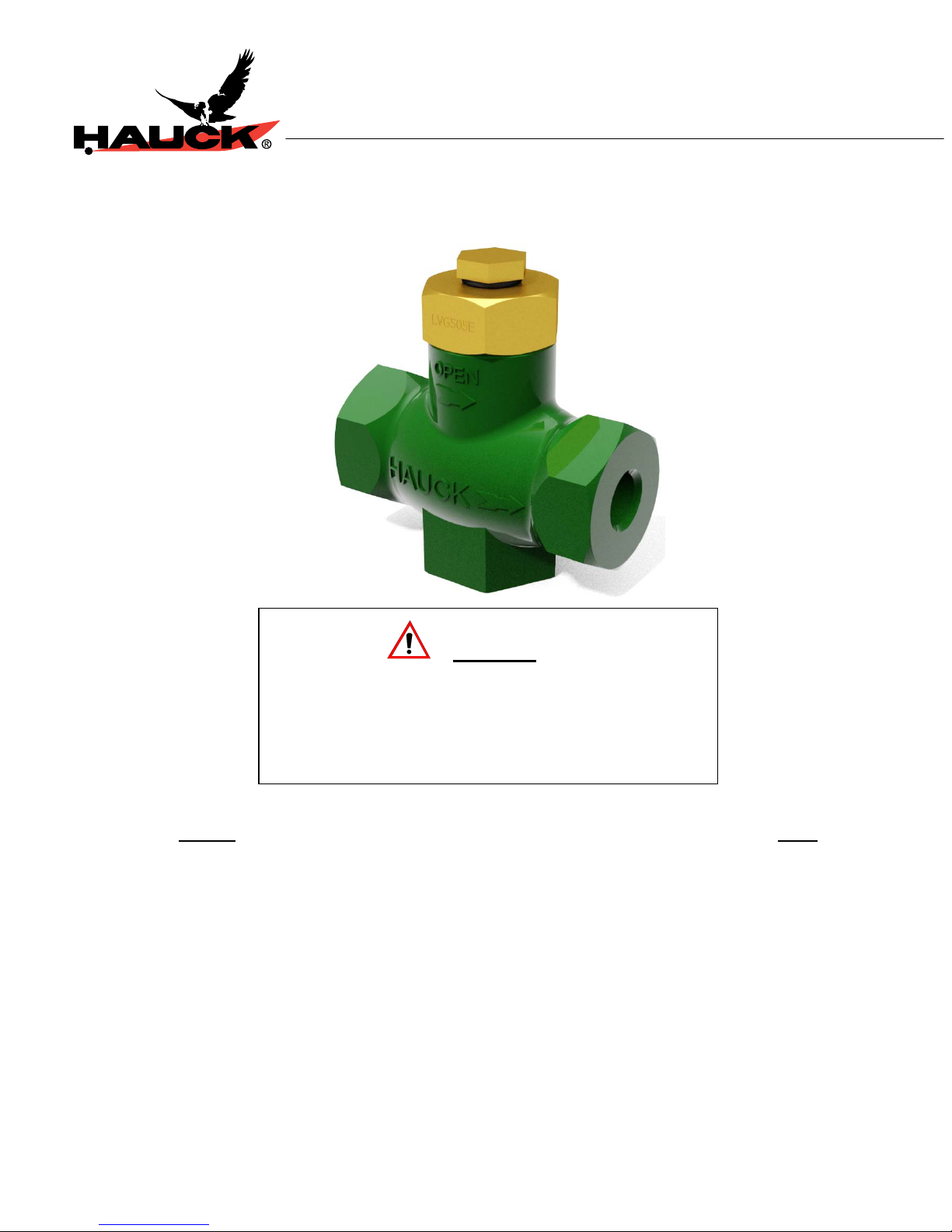
GAS LIMITING ORIFICE VALVES
WARNING
These instructions are intended for use only by
experienced, qualified combustion start-up personnel.
Adjustment of this equipment and its components, by
unqualified personnel, can result in fire, explosion,
severe personal injury, or even death.
LVG SERIES
INSTRUCTIONS
LVG-9

Page 2
WARNING
This equipment is potentially dangerous with the possibility of serious personal injury
and property damage. Hauck Manufacturing Company recommends the use of flame
supervisory equipment and fuel safety shutoff valves. Furthermore, Hauck urges rigid
adherence to National Fire Protection Association (NFPA) standards and insurance
underwriter’s requirements. Operation and regular preventative maintenance of this
equipment should be performed only by properly trained and qualified personnel.
Annual review and upgrading of safety equipment is recommended.
A. GENERAL INFORMATION
The Hauck LVG Series Limiting Orifice Gas Valves are designed for use with each burner in a
multiple furnace application. They allow fine gas flow adjustment of individual burners to
achieve the desired air/gas ratio at each burner. The standard LVG series valves can be used
as straight through type valves, and are designed for use with any commercial fuel gas.
B. RECEIVING AND INSPECTION
Upon receipt, check each item on the bill of lading and/or invoice to determine that all
equipment has been received. A careful examination of all parts should be made to ascertain if
there has been any damage in shipment.
LVG-9
Page 3
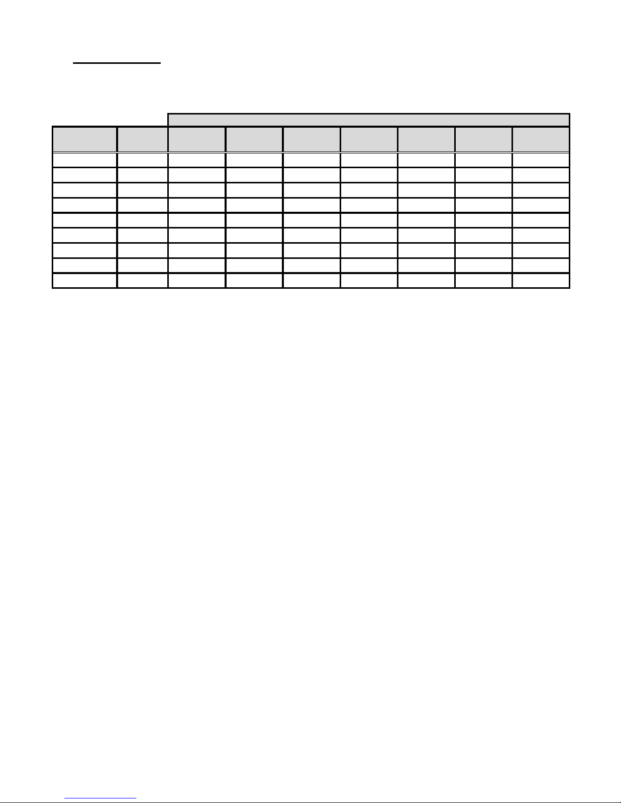
C. CAPACITIES
LVG-9
NATURAL GAS
Full Open Valve Capacity
PRESSURE DROP
Model No.
LVG 505E 1/2 NPT 275 410 575 757 1,055 1,290 1,470
LVG 507E 3/4 NPT 405 590 815 1,070 1,520 1,855 2,120
LVG 510D 1 NPT 635 870 1,230 1,625 2,245 2,750 3,155
LVG 512D 1-1/4 NPT 1,070 1,520 2,160 2,840 4,020 4,890 5,630
LVG 515D 1-1/2 NPT 1,500 2,140 3,000 3,930 5,560 6,740 7,680
LVG 520D 2 NPT 2,560 3,520 5,010 6,565 9,080 11,120 12,700
LVG 525A 2-1/2 NPT 3,985 5,630 7,970 10,480 14,830 18,160 20,960
LVG 530A 3 NPT 5,215 7,830 14,330 13,720 19,420 23,770 27,440
LVG 540A 4"FLG 9,370 13,240 18,740 24,640 34,880 42,700 49,270
Pipe 1"wc 2"wc 4"wc 6.9"wc 13.8"wc 20.8"wc 27.7"wc
Size 2.5 mbar 5 mbar 10 mbar 17.2 mbar 34.3 mbar 51.8 mbar 69 mbar
Notes
1. Capacities based on natural gas at 0.60 s.g. and 60°F (or 0°C).
2. Pressure drop measured across full open valve.
3. Maximum inlet pressure is 15 psig (1034 mbar)
4. For natural gas leakage rat es with valve fully closed, consult Hauck .

C. CAPACITIES (Continued)
LVG 505E (1/2")
Per centage o f Maximu m
Flow vs No. of Turns Open
100
80
60
40
20
0
Percentage of Max. Flow
01234567
No. of Turns Open
Percentage of Maximum Flow vs No. of
100
80
LVG 510D (1")
Turns Open
60
40
20
0
Per centage o f Max. F l o w
012345678910
No. of Turns Open
Percentage of Maximum Flow vs No. of
100
LVG 515D (1 1/2")
Turns Open
80
60
40
20
0
Percentage of Max. Flow
0123456789101112131415
No. of Tu r n s Open
LVG 507E (3/4")
Percentage of Maximum Flow vs No. of
Turns Open
100
80
60
40
20
0
Percentage of Max. Flow
Percentage of Max. Flow
Percentage of Max. Flow
012345678
No. o f Turns Op en
LVG 512D (1 1/4")
Percentage of Maximum Flow vs No. of
Turns Open
100
80
60
40
20
0
0123456789101112
No. of Turns Open
LV G 520D (2")
Percentage of Maximum Flow vs No. of
Turns Open
100
80
60
40
20
0
0123456789101112131415
No. of Turns Ope n
Page 4
LVG-9

C. CAPACITIES (Continued)
Percentage of Maximum Flow vs No. of Turns Open
100
90
80
70
60
50
40
30
20
10
0
Percentage of Max. Flow
0 2 4 6 8 10 12 14 16 18 20 22 24
Percentage of Maximum Flow vs No. of Turns Open
100
90
80
70
60
50
40
30
20
10
Percentage of Max. Flow
0
0 2 4 6 8 10 12 14 16 18 20 22 24
Percentage of Maximum Flow vs No. of Turns Open
100
90
80
70
60
50
40
30
20
10
Percentage of Max. Flow
0
0 4 8 1216202428323640
LVG 525A (2 1/2")
No. of Turns Open
LVG 530A (3")
No. of Turns Open
LVG 540A (4")
No. of Turns Open
Page 5
LVG-9

Page 6
D. DIMENSIONS
See appropriate Dimension sheet for detailed dimensional information.
LVG-9
E. INSTALLATION
The LVG valves are designed as straight through valves and feature an arrow indicating the
intended direction of flow.
NOTE
Tighten all connections to ANSI/ASME B1.20.1 specifications.
Install the LVG in the gas line as close to the burner as possible, downstream of a shutoff valve,
gas orifice meter and gas controlling valve, and in an area that allows easy access to the
valve’s adjusting mechanism.
X7026
(NOT TO SCALE)

Page 7
F. OPERATION
The LVG series valves can be used with any clean commercial fuel gas.
For flow adjustment, remove the hex screw cap from the valve. Using a flat-head screwdriver
(1/4" allen wrench on LVG 525 – 540 sizes), adjust the piston assembly until the desired flow
rate is achieved. Counterclockwise rotation increases gas flow.
G. MAINTENANCE
All LVG series valves are designed for maintenance free operation. Under normal usage, no
service should be necessary. For the LVG 505 - 520 size valves, the entire piston cartridge may
be removed for inspection or maintenance of the valve orifice. Remove the cartridge by
unscrewing the brass hex connection. Replace the cartridge when complete.
Replace the hex screw cap when adjustment is complete to seal the valve.
IMPORTANT
LVG-9
 Loading...