

Page 1

INSTRUCTIONS
IPG GAS PILOT BURNERS
TABLE OF CONTENTS
Subject
A. General Information ……………………………………………………….…..….……. 2
B. Receiving and Inspection ………………………………………….…….…...…….….. 2
C. Capacities ………….……………………………………………………………………. 3
D. Dimensions …………….………………………………………………………………... 6
E. Installation ……………………………………………………………………………….. 6
F. Ignition……………………………………………………………………………………. 6
G. Operation…………………………………………………………………………………. 9
H. Shutoff Valve Leak Testing…………………………………………………………….. 9
I. Maintenance……………………………………………………………………………… 9
These instructions are intended to serve as guidelines covering the installation, operation, and maintenance of Hauck equipment. While
every attempt has been made to ensure completeness, unforeseen or unspecified applications, details, and variations may preclude
covering every possible contingency. WARNING: TO PREVENT THE POSSIBILITY OF SERIOUS BODILY INJURY, DO NOT USE OR
OPERATE ANY EQUIPMENT OR COMPONENT WITH ANY PARTS REMOVED OR ANY PARTS NOT APPROVED BY THE
MANUFACTURER. Should further information be required or desired or should particular problems arise which are not covered
sufficiently for the purchaser's purpose, contact Hauck Mfg. Co.
HAUCK MANUFACTURING CO.,
9/12 www.hauckburner.com Fax: 717-273-9882
These instructions are intended for use only by experienced, qualified
combustion start-up personnel. Adjustment of this equipment and its
components by unqualified personnel can result in fire, explosion, severe
personal injury, or even death.
P.O. Box 90 Lebanon, PA 17042-0090 717-272-3051
WARNING
Page
IPG-9
Page 2
Page 2
IPG-9
WARNING
This equipment is potentially dangerous with the possibility of serious personal injury
and property damage. Hauck Manufacturing Company recommends the use of flame
supervisory equipment and fuel safety shutoff valves. Furthermore, Hauck urges rigid
adherence to National Fire Protection Association (NFPA) standards and insurance
underwriter’s requirements. Operation and regular preventative maintenance of this
equipment should be performed only by properly trained and qualified personnel.
Annual review and upgrading of safety equipment is recommended.
A. GENERAL INFORMATION
The Hauck Series IPG Gas Pilot provides a means of lighting the flame of Hauck burners and
many other industrial gas or oil burners. IPG pilots are engineered for exceptional flame stability
and long life, even under the most severe and adverse operating conditions. IPG pilots are
designed for electric spark ignition. The standard IPG Gas Pilots are suitable for firing into
neutral, negative or positive pressure applications.
The back-loaded feature offers the capability to compensate the pilot air/fuel ratio for variations
in furnace or burner pressure.
B. RECEIVING AND INSPECTION
Upon receipt, check each item on the bill of lading and/or invoice to determine that all
equipment has been received. A careful examination of all parts should be made to ascertain if
there has been any damage in shipment.
If the installation is delayed and the equipment is stored outside,
provide adequate protection as dictated by climate and period of
exposure. Special care should be given to all motors and bearings, if
applicable, to protect them from rain or excessive moisture.
IMPORTANT
Page 3
Page 3
IPG-9
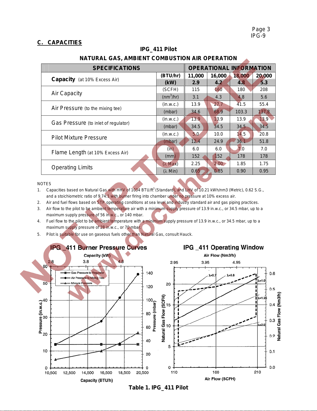
C. CAPACITIES
IPG_411 Pilot
NATURAL GAS, AMBIENT COMBUSTION AIR OPERATION
Capacity
Air Capacity
Air Pressure (to the mixing tee)
Gas Pressure (to inlet of regulator)
Pilot Mixture Pressure
Flame Length (at 10% Excess Air)
Operating Limits
(at 10% Excess Air)
SPECIFICATIONS OPERATIONAL INFORMATION
(BTU/hr)
(kW) 2.9 4.2 4.8 5.3
(SCFH) 115 160 180 208
(nm3/hr) 3.1 4.3 4.8 5.6
(in.w.c.) 13.9 27.7 41.5 55.4
(mbar) 34.6 68.9 103.3 137.8
(in.w.c.) 13.9 13.9 13.9 13.9
(mbar) 34.5 34.5 34.5 34.5
(in.w.c.) 5.0 10.0 14.5 20.8
(mbar) 12.4 24.9 36.1 51.8
(in) 6.0 6.0 7.0 7.0
(mm) 152 152 178 178
( Max)
( Min)
11,000 16,000 18,000 20,000
2.25 2.00 1.85 1.75
0.65 0.85 0.90 0.95
NOTES
1. Capacities based on Natural Gas with HHV of 1034 BTU/ft
and a stoichiometric ratio of 9.74:1 with burner firing into chamber under no pressure at 10% excess air.
2. Air and fuel flows based on STP operating conditions at sea level and industry standard air and gas piping practices.
3. Air flow to the pilot to be ambient temperature air with a minimum supply pressure of 13.9 in.w.c., or 34.5 mbar, up to a
maximum supply pressure of 56 in.w.c., or 140 mbar.
4. Fuel flow to the pilot to be ambient temperature with a minimum supply pressure of 13.9 in.w.c., or 34.5 mbar, up to a
maximum supply pressure of 28 in.w.c., or 70 mbar.
5. Pilot is suitable for use on gaseous fuels other than Natural Gas, consult Hauck.
3
(Standard), and LHV of 10.21 kWh/nm3 (Metric), 0.62 S.G.,
Table 1. IPG_411 Pilot
Page 4
Page 4
IPG-9
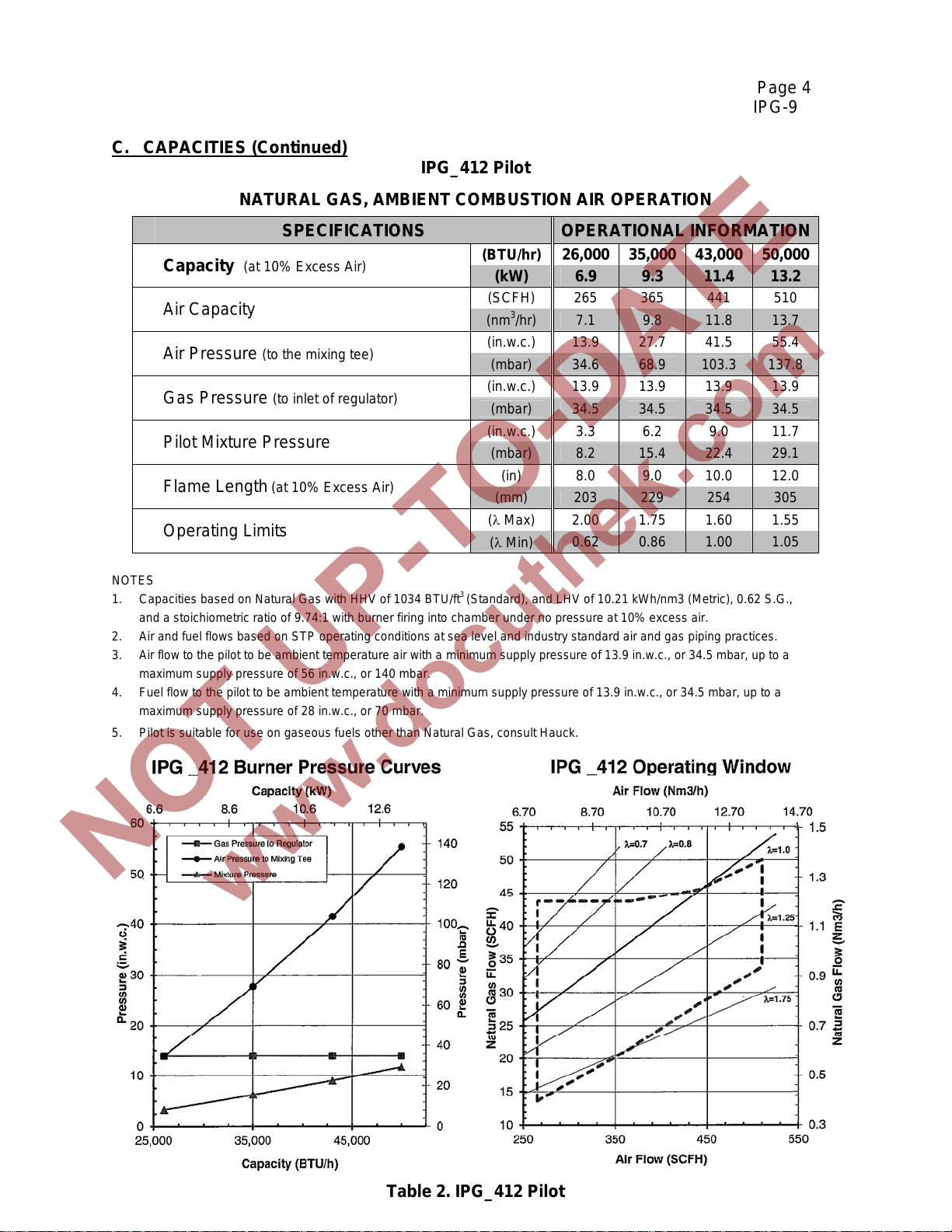
C. CAPACITIES (Continued)
IPG_412 Pilot
NATURAL GAS, AMBIENT COMBUSTION AIR OPERATION
Capacity
Air Capacity
Air Pressure (to the mixing tee)
Gas Pressure (to inlet of regulator)
Pilot Mixture Pressure
Flame Length (at 10% Excess Air)
Operating Limits
(at 10% Excess Air)
SPECIFICATIONS OPERATIONAL INFORMATION
(BTU/hr)
(kW) 6.9 9.3 11.4 13.2
(SCFH) 265 365 441 510
(nm3/hr) 7.1 9.8 11.8 13.7
(in.w.c.) 13.9 27.7 41.5 55.4
(mbar) 34.6 68.9 103.3 137.8
(in.w.c.) 13.9 13.9 13.9 13.9
(mbar) 34.5 34.5 34.5 34.5
(in.w.c.) 3.3 6.2 9.0 11.7
(mbar) 8.2 15.4 22.4 29.1
(in) 8.0 9.0 10.0 12.0
(mm) 203 229 254 305
( Max)
( Min)
26,000 35,000 43,000 50,000
2.00 1.75 1.60 1.55
0.62 0.86 1.00 1.05
NOTES
1. Capacities based on Natural Gas with HHV of 1034 BTU/ft
and a stoichiometric ratio of 9.74:1 with burner firing into chamber under no pressure at 10% excess air.
2. Air and fuel flows based on STP operating conditions at sea level and industry standard air and gas piping practices.
3. Air flow to the pilot to be ambient temperature air with a minimum supply pressure of 13.9 in.w.c., or 34.5 mbar, up to a
maximum supply pressure of 56 in.w.c., or 140 mbar.
4. Fuel flow to the pilot to be ambient temperature with a minimum supply pressure of 13.9 in.w.c., or 34.5 mbar, up to a
maximum supply pressure of 28 in.w.c., or 70 mbar.
5. Pilot is suitable for use on gaseous fuels other than Natural Gas, consult Hauck.
3
(Standard), and LHV of 10.21 kWh/nm3 (Metric), 0.62 S.G.,
Table 2. IPG_412 Pilot
Page 5
Page 5
IPG-9
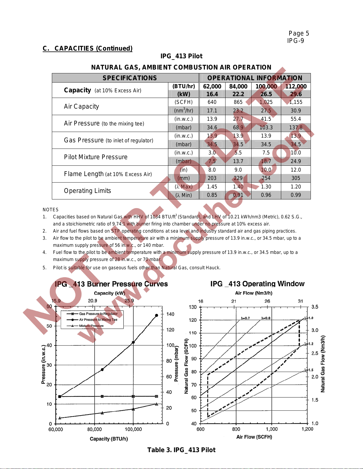
C. CAPACITIES (Continued)
IPG_413 Pilot
NATURAL GAS, AMBIENT COMBUSTION AIR OPERATION
Capacity
Air Capacity
Air Pressure (to the mixing tee)
Gas Pressure (to inlet of regulator)
Pilot Mixture Pressure
Flame Length (at 10% Excess Air)
Operating Limits
SPECIFICATIONS OPERATIONAL INFORMATION
(at 10% Excess Air)
(BTU/hr)
(kW) 16.4 22.2 26.5 29.6
(SCFH) 640 865 1,025 1,155
(nm3/hr) 17.1 23.2 27.5 30.9
(in.w.c.) 13.9 27.7 41.5 55.4
(mbar) 34.6 68.9 103.3 137.8
(in.w.c.) 13.9 13.9 13.9 13.9
(mbar) 34.5 34.5 34.5 34.5
(in.w.c.) 3.0 5.5 7.5 10.0
(mbar) 7.5 13.7 18.7 24.9
(in) 8.0 9.0 10.0 12.0
(mm) 203 229 254 305
( Max)
( Min)
62,000 84,000 100,000 112,000
1.45 1.40 1.30 1.20
0.85 0.91 0.96 0.99
NOTES
1. Capacities based on Natural Gas with HHV of 1034 BTU/ft
and a stoichiometric ratio of 9.74:1 with burner firing into chamber under no pressure at 10% excess air.
2. Air and fuel flows based on STP operating conditions at sea level and industry standard air and gas piping practices.
3. Air flow to the pilot to be ambient temperature air with a minimum supply pressure of 13.9 in.w.c., or 34.5 mbar, up to a
maximum supply pressure of 56 in.w.c., or 140 mbar.
4. Fuel flow to the pilot to be ambient temperature with a minimum supply pressure of 13.9 in.w.c., or 34.5 mbar, up to a
maximum supply pressure of 28 in.w.c., or 70 mbar.
5. Pilot is suitable for use on gaseous fuels other than Natural Gas, consult Hauck.
3
(Standard), and LHV of 10.21 kWh/nm3 (Metric), 0.62 S.G.,
Table 3. IPG_413 Pilot
Page 6
Page 6
IPG-9
D. DIMENSIONS
See appropriate Dimension sheet for detailed dimensional information.
E. INSTALLATION
1. Ensure that all components of the factory assembled pilot are present and properly
connected. The pilot unit consists of a low pressure gas regulator, air ball valve, gas ball
valve, gas mixer, pilot nozzle assembly, union (threaded pilots only), and flexible pipe nipple.
2. Install the pilot assembly in the air and gas lines. The gas pressure regulator is used as a
zero governor and is suitable for any mounting position without restriction.
a. Connect the air piping to the inlet side of the air ball valve. Low pressure air should be
supplied at a constant pressure ranging from 14 - 55 in.w.c. (3.5 - 13.7 kPa) at the inlet
of the ball valve.
b. Connect the gas piping to the inlet side of the gas ball valve. Low pressure gas should
be supplied at approximately 14 in.w.c. (3.5 kPa) at the inlet of the regulator. The
regulator is designed to operate from 13.9 - 27.7 in.w.c. (3.4 - 6.9 kPa); maximum
allowable inlet pressure is 27.7 in.w.c. (6.9 kPa).
c. Ensure that the air and gas ball valves are fully closed.
F. IGNITION
WARNING
Adjustment of this equipment by unqualified personnel
can result in fire, explosion, severe personal injury, or
even death.
NOTE
To reduce pressure losses, use adequate sized pipe and minimize elbows in the air and
gas lines to the pilot assembly. It is recommended that the air and gas supply be equal
to or greater than their respective pilot air and gas connection sizes. If the pilot is
installed at the end of a long run of pipe or will be operated in a dirty environment, it is
recommended that a sediment trap be installed in the pilot air line.
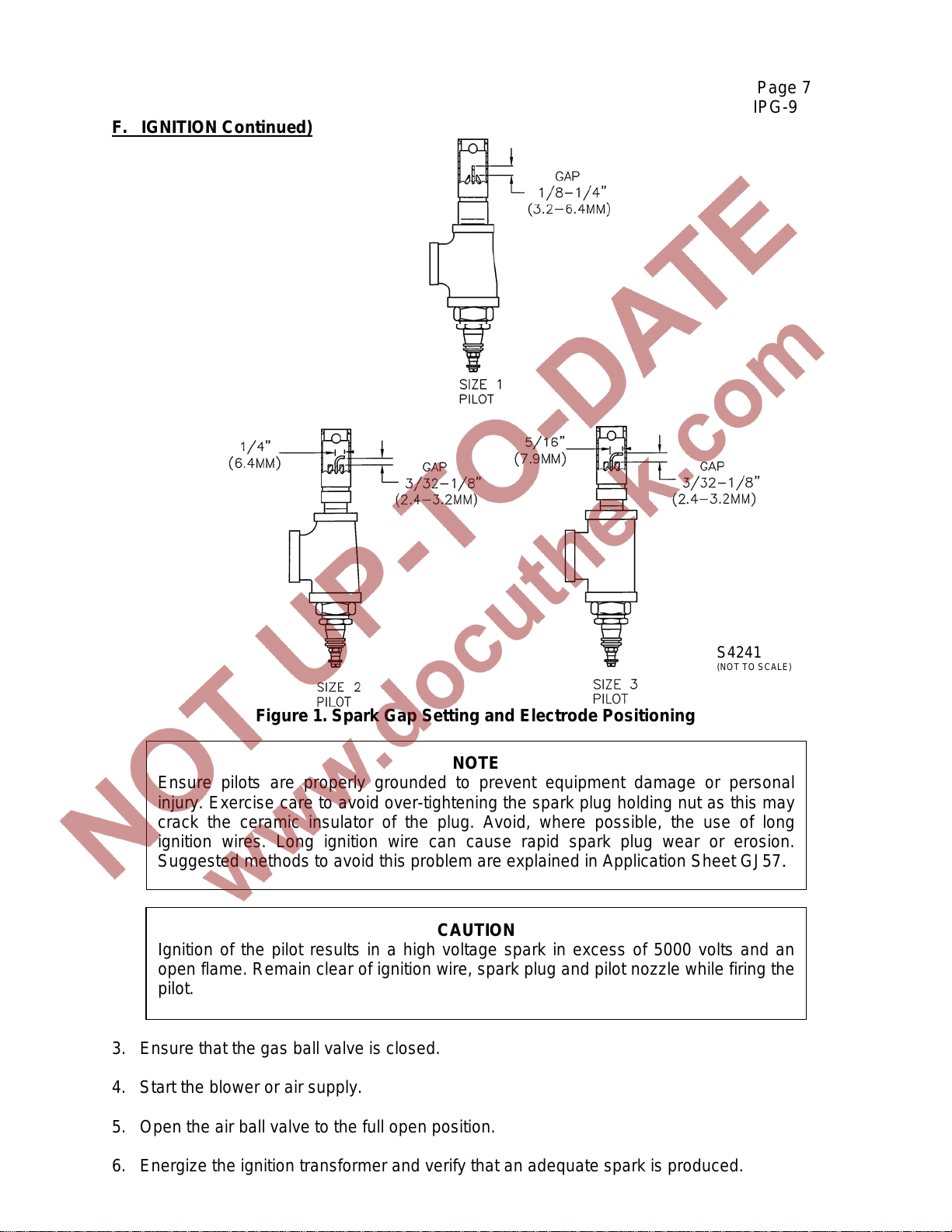
1. Be sure the spark plug is set as shown in Figure 1. Ideally, initial pilot set-up should be done
with the pilot outside of the burner.
2. Connect a 5000/6000 volt standard coil type ignition transformer to the spark plug on the
spark igniter using a high voltage ignition wire. Ensure that the spark plug’s wire electrode is
centered in the pilot nozzle.
Page 7
Page 7
IPG-9
F. IGNITION Continued)
S4241
(NOT TO SCALE)
Figure 1. Spark Gap Setting and Electrode Positioning
Ensure pilots are properly grounded to prevent equipment damage or personal
injury. Exercise care to avoid over-tightening the spark plug holding nut as this may
crack the ceramic insulator of the plug. Avoid, where possible, the use of long
ignition wires. Long ignition wire can cause rapid spark plug wear or erosion.
Suggested methods to avoid this problem are explained in Application Sheet GJ57.
NOTE
Ignition of the pilot results in a high voltage spark in excess of 5000 volts and an
open flame. Remain clear of ignition wire, spark plug and pilot nozzle while firing the
pilot.
CAUTION
3. Ensure that the gas ball valve is closed.
4. Start the blower or air supply.
5. Open the air ball valve to the full open position.
6. Energize the ignition transformer and verify that an adequate spark is produced.
Page 8
Page 8
IPG-9
7. Open the gas ball valve fully. This ball valve should be open fully at all times when the
pilot is burning.
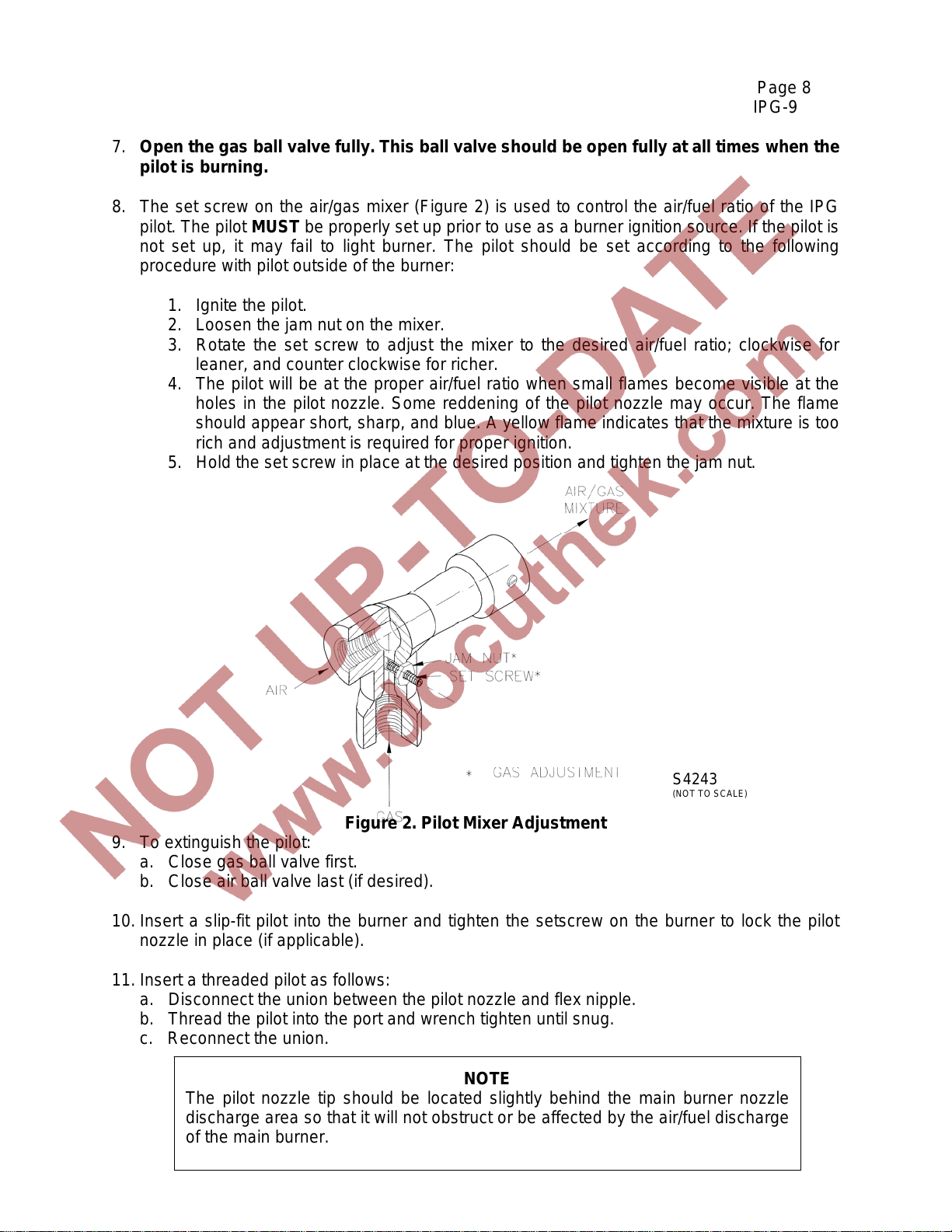
8. The set screw on the air/gas mixer (Figure 2) is used to control the air/fuel ratio of the IPG
pilot. The pilot MUST be properly set up prior to use as a burner ignition source. If the pilot is
not set up, it may fail to light burner. The pilot should be set according to the following
procedure with pilot outside of the burner:
1. Ignite the pilot.
2. Loosen the jam nut on the mixer.
3. Rotate the set screw to adjust the mixer to the desired air/fuel ratio; clockwise for
leaner, and counter clockwise for richer.
4. The pilot will be at the proper air/fuel ratio when small flames become visible at the
holes in the pilot nozzle. Some reddening of the pilot nozzle may occur. The flame
should appear short, sharp, and blue. A yellow flame indicates that the mixture is too
rich and adjustment is required for proper ignition.
5. Hold the set screw in place at the desired position and tighten the jam nut.
S4243
(NOT TO SCALE)
Figure 2. Pilot Mixer Adjustment
9. To extinguish the pilot:
a. Close gas ball valve first.
b. Close air ball valve last (if desired).
10. Insert a slip-fit pilot into the burner and tighten the setscrew on the burner to lock the pilot
nozzle in place (if applicable).
11. Insert a threaded pilot as follows:
a. Disconnect the union between the pilot nozzle and flex nipple.
b. Thread the pilot into the port and wrench tighten until snug.
c. Reconnect the union.
The pilot nozzle tip should be located slightly behind the main burner nozzle
discharge area so that it will not obstruct or be affected by the air/fuel discharge
of the main burner.
NOTE
Page 9
Page 9
IPG-9
G. OPERATION
When properly adjusted, the pilot should produce a sharp, short, blue flame. If adjustment is
necessary, refer to the Ignition section.
H. SHUTOFF VALVE LEAK TESTING
Both safety shutoff valves in the gas pilot manifold must be leak tested by qualified personnel as
recommended by NFPA 86.
WARNING
Do not attempt to operate a combustion system
with leaks present.
I. MAINTENANCE
All components of the pilot assembly are engineered to provide maintenance free operation. It is
sometimes necessary, however, to clear the mixer jet of any debris as this causes mixer
capacity to diminish. The mixer jet is easily cleaned by removing the air piping downstream of
the air ball valve and running a wire into the mixing tee opening through the jet. The gas inlet of
the mixer can also be cleaned by the same method. Fully removing the adjustment screw also
provides access to clean the mixer.
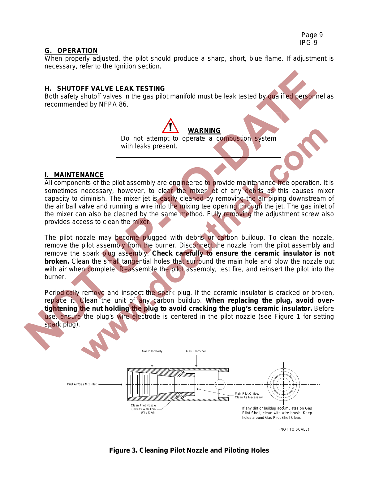
The pilot nozzle may become plugged with debris or carbon buildup. To clean the nozzle,
remove the pilot assembly from the burner. Disconnect the nozzle from the pilot assembly and
remove the spark plug assembly. Check carefully to ensure the ceramic insulator is not
broken. Clean the small tangential holes that surround the main hole and blow the nozzle out
with air when complete. Reassemble the pilot assembly, test fire, and reinsert the pilot into the
burner.
Periodically remove and inspect the spark plug. If the ceramic insulator is cracked or broken,
replace it. Clean the unit of any carbon buildup. When replacing the plug, avoid over-
tightening the nut holding the plug to avoid cracking the plug’s ceramic insulator. Before
use, ensure the plug’s wire electrode is centered in the pilot nozzle (see Figure 1 for setting
spark plug).
Pilot Air/Gas Mix Inlet
(NOT TO SCALE)
Gas Pilot Body Gas Pilot Shell
Clean Pilot Nozzle
Orifices With Thin
Wire & Air.
Main Pilot Orifice.
Clean As Necessary
If any dirt or buildup accumulates on Gas
Pilot Shell, clean with wire brush. Keep
holes around Gas Pilot Shell Clear.
Figure 3. Cleaning Pilot Nozzle and Piloting Holes
Page 10

Page 10
IPG-9
This page left intentionally blank.
HAUCK MANUFACTURING CO., P.O. Box 90 Lebanon, PA 17042-0090 717-272-3051
www.hauckburner.com Fax: 717-273-9882
 Loading...