

Page 1
Workshop manual
438 202 01 - Printed in Germany
1 D . .
Page 2

Page 3

Foreword
1. General
Engine illustrations
Technical data
Type plate data
Lubrication oil circuit
Special tools and
workshop equipments
Jointing material / Sealing and
bonding agents
2. Additional equipments
A 01.00 Fuel
A 01.10 Fuel tank
A 01.40 Fuel feed pumps
A 02:00 Combustion air
A 02.10 Oil bath air filters
A 02.11 Dry type air filters
A 02.13 Service indicators;
vacuum gauges
A 02.20 Pre-cleaners; cyclons
A 03.00 Exhausts
A 03.12 Exhaust-silencers,
Protection guard
A 04.00 Start mechanical
A 04.10 Starting handles
without supports
A 04.11 Starting handle supports
A 04.12 Cranking claws
A 04.30 Rope starts
A 05.00 Start electrical
A 05.20 Starter motors
A 05.40 Alternator / Magnet segments
A 05.41 Alternator / Coils
A 05.80 Ring gears
A 07.00 Lubrication oil
A 07.20 Lub.-oil filters, strainers
A 07.30 Oil sumps
A 09.00 Speed controls
A 09.60 Low idle speed stabilization
A 11.00 Remote engine controls
A 11.10 Stop devices
A 11.30 Auto. Shut-off device
A 15.00 Housings, flanges,
adaptors
A 15.20 Adaptor housings
Contents
Page 4

3. Basic engine
M–Disassembly cross reference scheme
M 01.00 Crankcase
M 01.10 Crankcase, nozzle
and bearings
M 01.11 Plugs
M 01.20 Crankshaft-thrustplate
and cam followers
M 01.30 Oil sump and suction sieve
M 01.31 Oil sump 1 D 50
M 01.40 Base plate and
oil pressure relief valve
M 01.50 Cyl.-head screw sealants
M 02.00 Crankshaft
M 02.10 Wear and grinding dimensions
M 02.20 Crankshaft gearwheel and
stubshafts
M 02.30 Crankshaft / Wear sleeve
M 03.00 Bearing flange
M 03.10 Bearing flange 1D 90 V/W
M 04.00 Camshaft and balancer unit
M 05.00 Piston with connecting rod
M 05.10 Piston and piston rings
M 05.20 Connecting rod
M 06.00 Cylinder
M 07.00 Cylinder head
M 07.10 Rockers and decompression
device
M 07.20 Bumping clearance
M 07.30 Cyl.-head and oil supply pipe
M 07.40 Valves, valve guides and
valve seats
M 08.00 Cover for cylinder head
M 09.00 Pushrods / Protection tubes
M 10.00 Oil pump / Governor
M 11.00 Timing cover
M 12.00 Extra fuel device
M 14.00 Fuel-injection equipment
M 14.10 Fuel pressure pipe
M 14.20 Injector
M 14.30 Injection pump
M 14.40 Roller tappet
M 17.00 Flywheel
M 26.00 Cowling / Air duct
M 31.00 Breather system
M 32.00 Speed control
M 35.00 Capsule
4. Data sheets
Injection equipment adjustment data
Governor equipment
General adjustment and testing data
Screw tightening torques
Designations in circuit diagrams
HATZ wiring designations
Electrical circuit diagrams
Circuit diagram for measuring
currents and voltages
Generator output characteristic
Troubleshooting – electrical system
Contents
Page 5

Foreword
This Workshop Manual covers the latest technical developments according to
month/year indicated on each page. It has been written in such a way, that it contains all
dismantling and assembly instructions in accordance with the table of contents, including all required data etc., so as to permit a trained mechanic to carry out correct and
professional repairs.
We have not included information such as cleaning parts, replacing of "O" Rings,
gaskets, oil seals etc. since it is assumed, of course, that the mechanic will be aware of
the necessity of carrying out such work.
Use only the tools prescribed or absolutely identical tools when carrying out work of
whatever nature.
It has been assumed that a standard set of workshop tools is available.
Please refer to the instruction book for maintenance work, operating materials and trouble shooting information.
Use only GENUINE HATZ PARTS for repairs!
Only these parts guarantee perfect dimensional accuracy and quality.
For the rest, please observe the general legal regulations and the regulations of the responsible professional associations.
Discrepancies may occur between the described features and actual features owing to
special equipment, and it has not been possible to allow for such discrepancies either in
the Workshop Manual or in the spare parts list.
Should you have any difficulties, please contact your nearest HATZ-Service agent.
Page 6

Page 7

1
1D . . / 03.06
1. General
Page 8
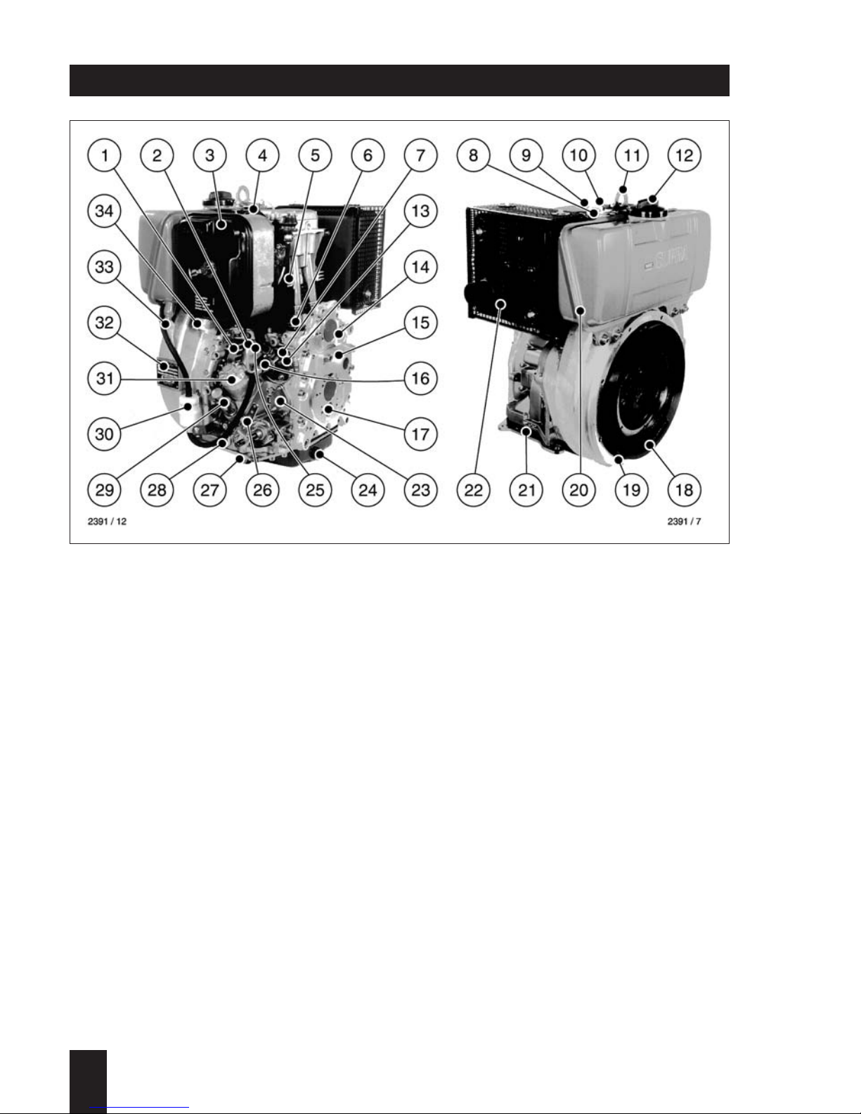
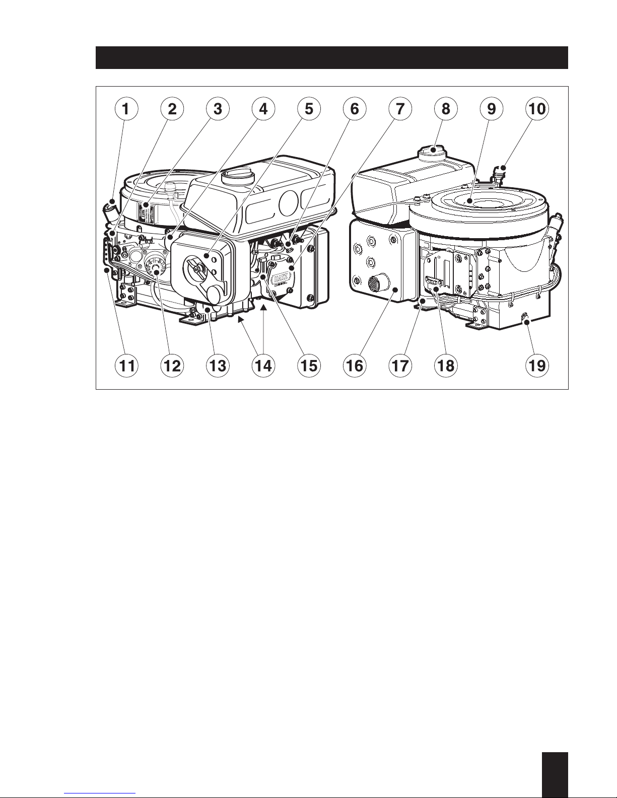
1 Cooling air inlet
2 Oil pressure switch
3 Dry type air cleaner
4 Decompression lever
5 Cooling air outlet
6 Extra fuel device
7 Injection pump
8 Injector
9 Cylinder head cover
10 Cold start-oil priming device
11 Lifting bracket, max. 120 kg / 265 lb
12 Fuel filler cap
13 Stop lever
14 Timing cover
15 Guiding shell for starting handle
16 Fuel pressure pipe
17 Governor
1
1D . . / 03.06
18 Flywheel
19 Engine flange
20 Fuel tank
21 Engine base plate
22 Exhaust silencer
23 Fuel feed pump (mounting pos.)
24 Oil drain plug, governor side
25 Injection pump bleeder valve
26 Speed control lever
27 Oil drain plug, control side
28 Oil pressure relief valve
29 Oil filling hole and dipstick
30 Fuel filter
31 Oil filter (optional)
32 Type plate
33 Fuel tank drain plug
34 Combustion air intake
Engine illustrations
Engine 1D30, 1D31, 1D40, 1D41, 1D50, 1D60, 1D80, 1D81, 1D90 S/Z/T/U
Page 9
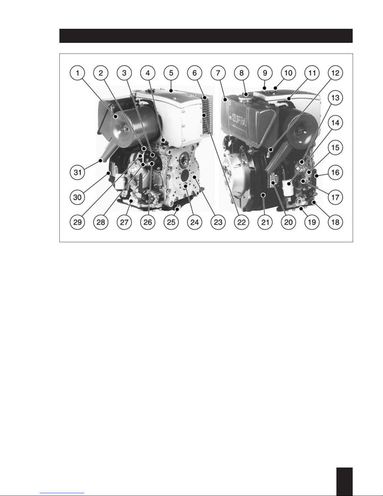
16 Speed control lever
17 Oil filling hole and dipstick
18 Engine base plate
19 Oil drain plug, control side
20 Type plate
21 Engine flange
22 Cooling air outlet
23 Timing cover
24 Governor
25 Oil drain plug, governor side
26 Injection pump
27 Oil pressure relief valve
28 Fuel pressure pipe
29 Cooling air inlet
30 Flywheel
31 Combustion air intake
1
1D . . / 03.06
1 Air filter
2 Oil pressure switch
3 Injection pump bleeder valve
4 Extra fuel device
5 Air cowling cover
6 Exhaust silencer
7 Fuel tank
8 Fuel filler cap
9 Lifting bracket, max. 120 kg / 265 lb
10 Cold start-oil priming device
11 Decompression lever
12 Fuel tank drain plug
13 Oil filter (optional)
14 Fuel filter
15 Fuel feed pump (mounting pos.)
Engine illustrations
Noise-optimized version
Engine A1D35, A1D40, A1D41 S/Z/T/U
Page 10
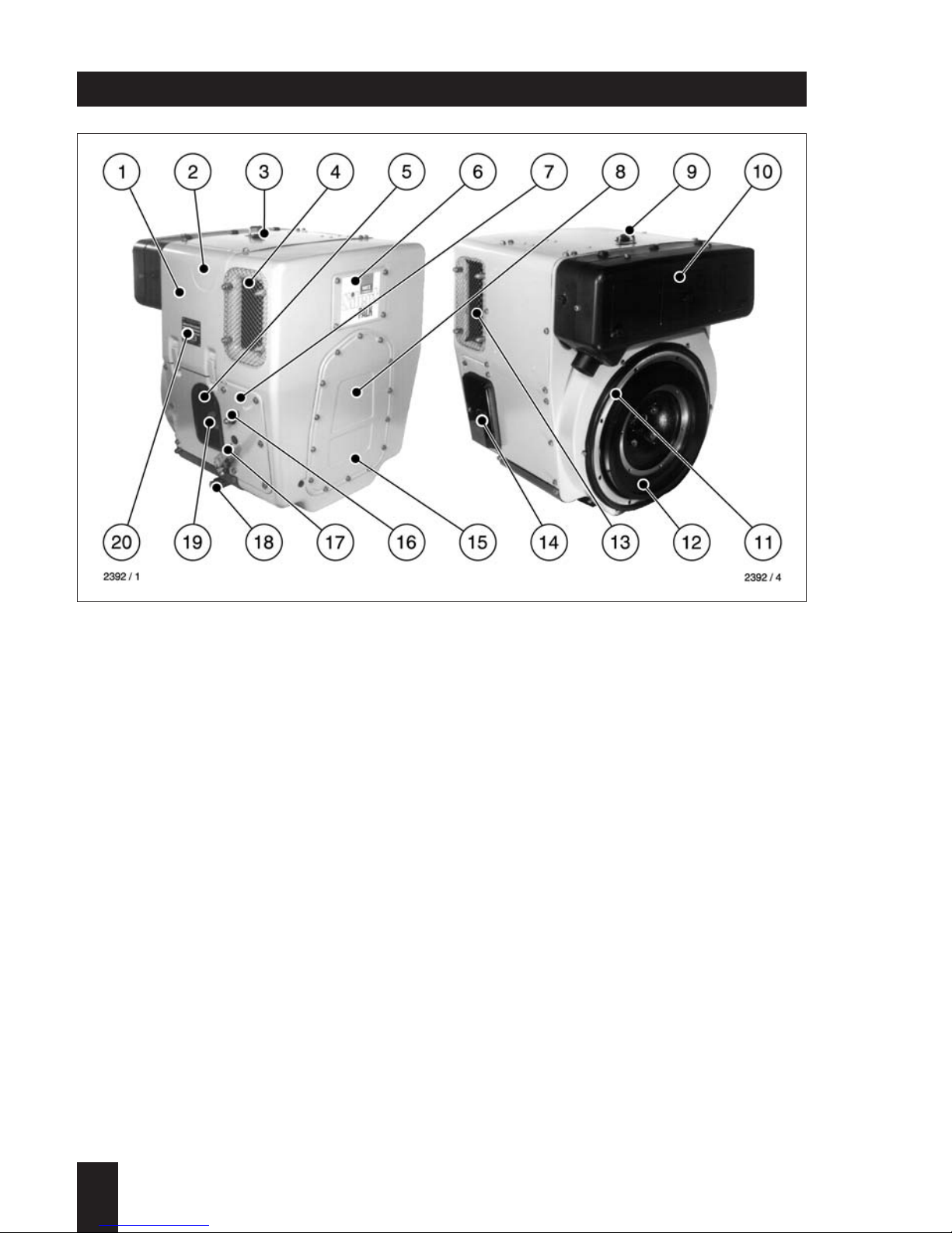
1 Capsule
2 Decompression lever
3 Cold start-oil priming device
4 Combustion and cooling air intake
5 Oil filter
6 Cleaning opening
7 Side panels
8 Access for starting handle
9 Lifting bracket, max. 120 kg / 265 lb
10 Exhaust silencer, enclosed
11 Engine flange
1
1D . . / 03.06
12 Flywheel
13 Cooling air outlet
14 Battery connections and central plug
for electrical system
15 Access to timing cover
16 Stop lever
17 Speed control lever
18 Oil drain plug
19 Oil filling hole and dipstick
20 Type plate
Engine illustrations
Fully encapsulated version
Engine 1D30C, 1D31C, 1D40C, 1D41C, 1D60C, 1D80C, 1D81C
Page 11
1 oil filler cap
2 dipstick
3 type plate
4 combustion air intake
5 dry type airfilter
6 fuel tank drain plug
7 cylinder head cover
8 fuel filler cap
9 cooling air inlet
10 mechanical maintenance indicator
11 speed control lever
12 oil filter
13 fuel filter
14 cooling air outle
15 decompression levert
16 exhaust silencer
17 electric starter
18 central plug f. electrical equipment
19 oil drain plug
Engine illustrations
Engine 1D90 V/W
1
1D . . / 03.06
Page 12

1
1D . . / 03.06
Type 1D30.. 1D40.. A1D35..
1D31.. A1D40..
Engine models S, Z, T, U, C S, Z, T, U, S, Z, T, U
Mode of operation Air-cooled four-stroke diesel engine
Combustion method Direct-injection
Number of cylinders 1 1 1
Bore / stroke mm 86/65 86/65 86/65
Cubic capacity cm
3
377 377 377
Compression ratio 1D30: 20.5:1 20.5:1 20.5:1
1D31: 21.0:1 22.0:1*
Direction of rotation 1D . . S / Z / C counter-clockwise
looking at the flywheel 1D . . T / U clockwise
Cooling air required
at 3000 min
-1
m3/min 6.0 6.0 6.0
Combustion air required
at 3000 min-1 m3/min 0.56 0.56 0.56
Oil capacity without oil filter approx. 1.1 1.1 1.1
with oil filter ltr. 1.2 1.2 1.2
Difference between approx. 0.4 0.4 0.4
„max“ and „min“ markings ltr.
Oil consumption Approx. 1% of fuel combustion at full load
Max. permissible inclination approx. 30° approx. 30° approx. 30°
in each direction during operation
Net weight
Engine models S, Z, T, U approx. 68 68 74
Engine models C kg 89 89 –
Model S: non-encapsulated, normal system of balancing, counter-clockwise rotation
Z: non-encapsulated, add. system of balancing, counter-clockwise rotation
T: non-encapsulated, normal system of balancing, clockwise rotation
U: non-encapsulated, add. system of balancing, clockwise rotation
C: SILENT PACK, add. system of balancing, counter-clockwise rotation
*Engines in connection with compaction units
Technical data
Page 13

1
1D . . / 03.06
Type 1D41.. 1D50.. 1D60..
A1D41..
Engine models S, Z, T, U, C S, Z S, Z, T, U, C
Mode of operation Air-cooled four-stroke diesel engine
Combustion method Direct-injection
Number of cylinders 1 1 1
Bore / stroke mm 90/65 97/70 88/85
Cubic capacity cm
3
413 517 517
Compression ratio 20.0:1 20.0:1 20.5:1
Direction of rotation 1D . . S / Z / C counter-clockwise
looking at the flywheel 1D . . T / U clockwise
Cooling air required
at 3000 min-1 m3/min 6.0 6.0 10.5
Combustion air required
at 3000 min-1 m3/min 0.62 0.78 0.78
Oil capacity without oil filter approx. 1.1 1.4 1.8
with oil filter ltr. 1.2 1.5 1.9
Difference between approx.
„max“ and „min“ markings ltr. 0.4 0.5 0.9
Oil consumption Approx. 1% of fuel combustion at full load
Max. permissible inclination
in each direction during operation approx. 30° approx. 30° approx. 30°
Net weight
Engine models S, Z, T, U approx. 68* 76 91
Engine models C kg 89 – 114
Model S: non-encapsulated,normal system of balancing,counter-clockwise rotation
Z: non-encapsulated, add. system of balancing, counter-clockwise rotation
T: non-encapsulated, normal system of balancing,clockwise rotation
U: non-encapsulated,add. system of balancing, clockwise rotation
C: SILENT PACK, add. system of balancing, counter-clockwise rotation
*A1D41: 74 kg
Technical data
Page 14

1
1D . . / 03.06
Technical data
Type 1D80.. 1D90.
1D81..
Engine models S, Z, T, U, C S, Z, V, W
Mode of operation Air-cooled four-stroke diesel engine
Combustion method Direct-injection
Number of cylinders 1 1
Bore / stroke mm 100/85 104/85
Cubic capacity cm
3
667 722
Compression ratio 20.5:1 20.5:1
Direction of rotation 1D . . S / Z / C / V / W counter-clockwise
looking at the flywheel 1D . . T / U clockwise
Cooling air required
at 3000 min-1 m3/min 10.5 10.5
Combustion air required
at 3000 min-1 m3/min 1.0 1.1
Oil capacity without oil filter approx. 1.8 1.8
with oil filter ltr. 1.9 1.9
Difference between approx.
„max“ and „min“ markings ltr. 0.9 0.9
Oil consumption Approx. 1% of fuel combustion at full load
Max. permissible inclination
in each direction during operation approx. 30° approx. 30°
Net weight
Engine models S/Z/T/U/V/W approx. 91 92
Engine models C 121 –
Model S: non-encapsulated, normal system of balancing, counter-clockwise rotation
Z: non-encapsulated, add. system of balancing, counter-clockwise rotation
T: non-encapsulated, normal system of balancing, clockwise rotation
U: non-encapsulated, add. system of balancing, clockwise rotation
C: SILENT PACK, add. system of balancing, counter-clockwise rotation
V: vertical crankshaft, non-encapsulated, normal system of balancing,
counter-clockwise rotation
W: vertical crankshaft, non-encapsulated, add. system of balancing,
counter-clockwise rotation
Page 15
1
1D . . / 03.06
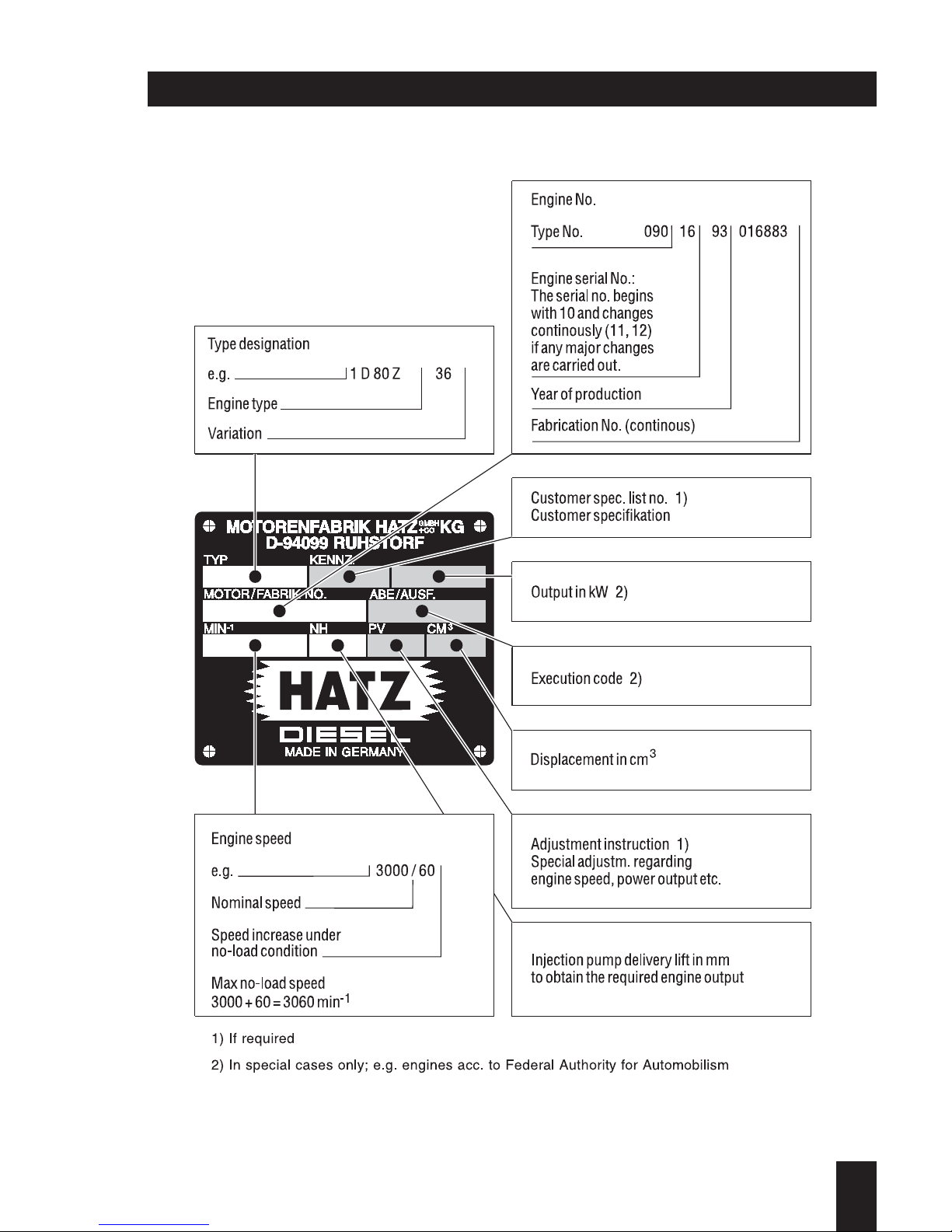
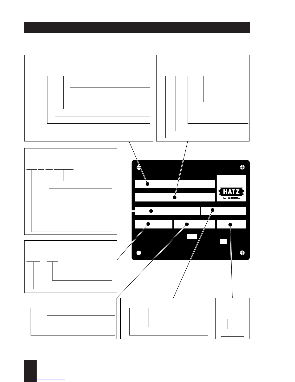
Type plate data
Page 16
EPA / Carb type plate data
ENG.FAM.
TYPE / SPEC. / FDT
MIN
SERIAL NO.
NH / kW
-1
MOTORENFABRIK HATZ KG·D-94099 RUHSTORF
CM3 / PV
BUILD DATE
IMPORTANT ENGINE INFORMATION
This engine conforms to MY U.S. EPA regulations large
nonroad compression-ignition engines and MY California
regulation for off-road compression-ignition engines.
Refer to owner's manual
for maintenance specifications and adjustments.
VARIABLE SPEED
GMBH
CO
+
Made in Germany
0.98 10.4 0667 189A
0504
1D81 Z 216B 13.04 HZX L.667 V 83
2950 290
073 23 04 083019
Rated power in kW
Injection pump delivery lift
in mm to obtain the required
power output
Special adjustment
instruction
Displacement in cm
3
Year
Month
Variation
Customer specification
(only for special
equipment)
Engine type
Static timing
(begin of fuel
delivery)
V = variable speed application
C = constant speed application
A = V + C as well
Displacement (in cm
3
or liters)
Diesel engine (Benzin/gasoline = S)
Manufactorer HZX = HATZ
Manuf. year (X = 1999, Y = 2000, 1 = 2001,...)
Type code
Speed increase under
no-load condition
Nominal speed
Engine serial No.:
The serial No. beginns
with 10 and changes
continously if any major
changes are carried out
Year of production
Type No.
Fabrication No.
Manuf. year
Type / Spec./ FDTEngine family
Engine speed
Engine number
1
1D . . / 03.06
Page 17
1
1D . . / 03.06
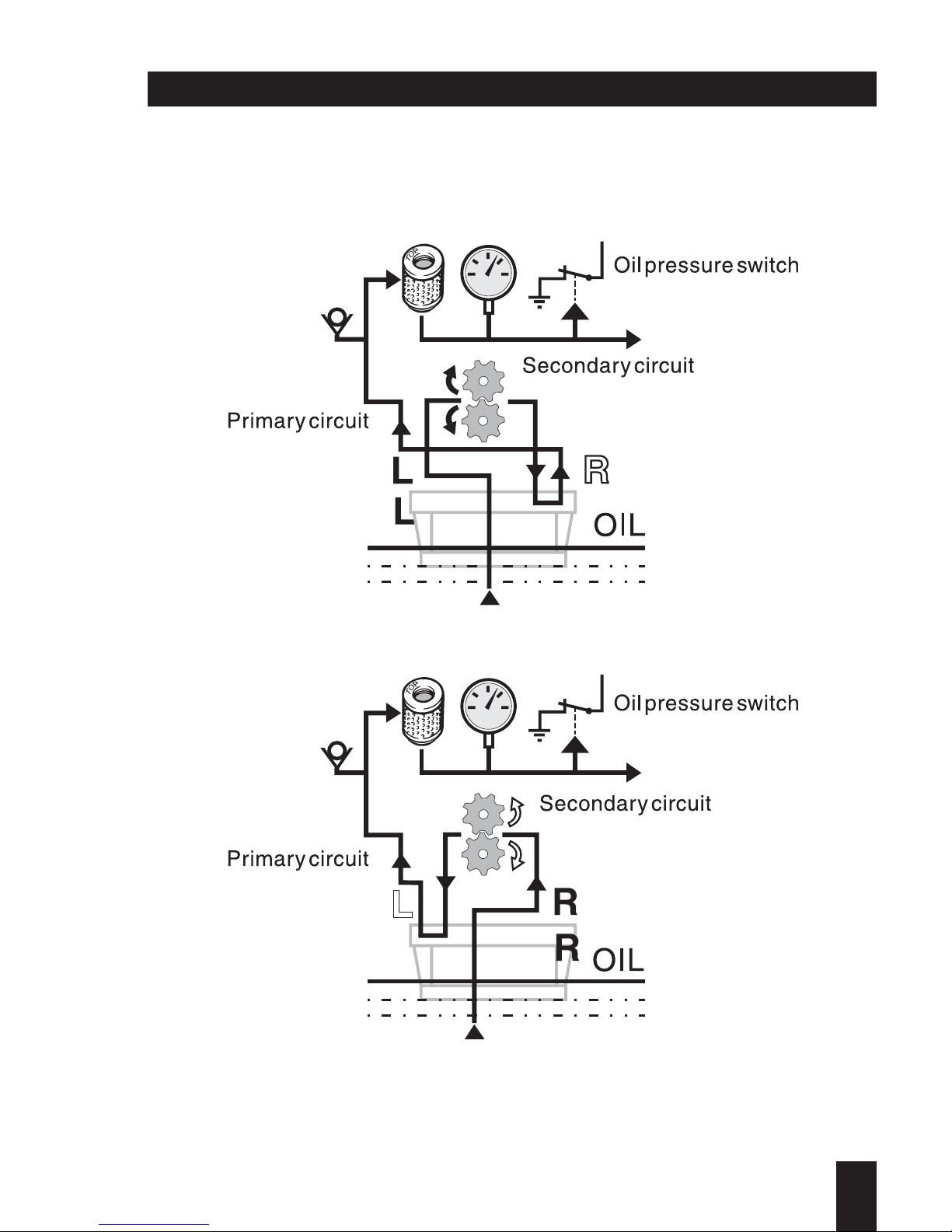
Lubrication oil circuit
Page 18

1
1D . . / 03.06
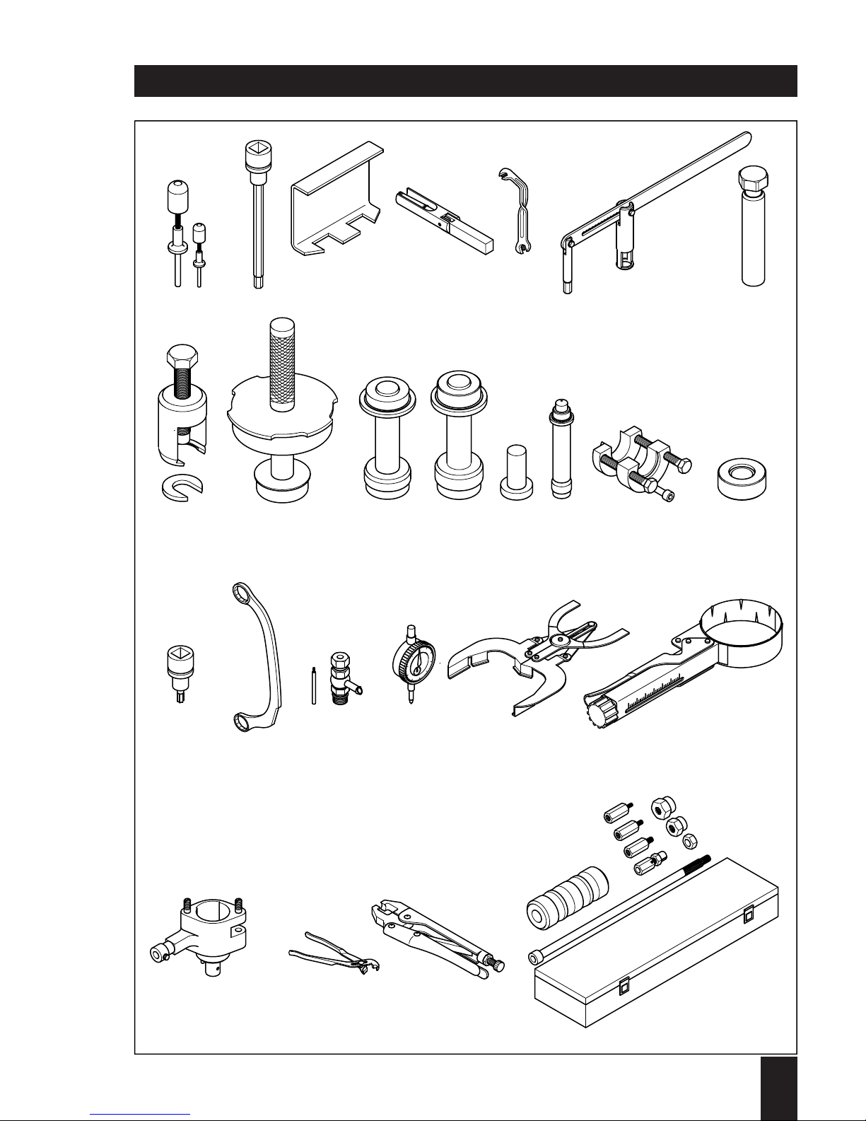
Special tools and workshop equipments
Engine series 1 D . . (SUPRA)
Bezeichnung
Verwendung
bei Typen
30-50 60-90
1
2
3
3
4
5
6
7
8
9
9
10
11
11
12
13
14
15
16
17
18
18
19
20
21
22
23
24
25
644 345 90
630 815 00
629 301 00
629 102 00
627 501 00
632 579 00
629 223 01
631 392 00
603 823 91
629 016 02
629 298 02
627 496 02
627 398 02
629 299 02
629 284 00
627 494 00
634 147 00
627 495 02
627 500 00
631 133 01
665 030 91
625 401 90
612 087 00
612 090 01
626 383 00
639 477 00
636 421 00
640 564 00
626 753 91
Clip tool for lead plugs
Allen socket 6 mm lg 1/2"
Clamp for pushrod tube
Clamp for pushrod tube
Retainer for governor spring
Adjustment wrench
Valve lifter
Mandrel for valve stem seal cap
Multi-purpose extractor
Punch for main bearing gov.-side
Punch for main bearing gov.-side
Punch for outer camshaft bushing
Punch for main bearing flywheel side
Punch for main bearing flywheel side
Heating insert for gear/stubshaft
Drift punch for camshaft bushing
Comb. extractor f. gear + stubshaft
Assembly device for oil pump shaft
Torx-socket TX 30 – 1/2"
Ring spanner 18 x 19 for starter
Spill device for injection pump M18x1.5
Spill device for injection pump M20x1.5
Dial gauge – 1/100 mm
Piston ring pliers
Piston ring clamp.device ∅ 70-100 mm
Measuring device for injection pump
Pliers for EPA - radial (tamper-resistant)
Pliers for EPA - axial (tamper-resistant)
Impact hammer with fittings
xx
xx
x–
–x
xx
xx
xx
xx
xx
–x
x–
xx
–x
x–
xx
xx
xx
xx
xx
xx
xx
xx
xx
xx
xx
xx
xx
xx
xx
Ident-Nr.Nr.
Page 19
1
1D . . / 03.06
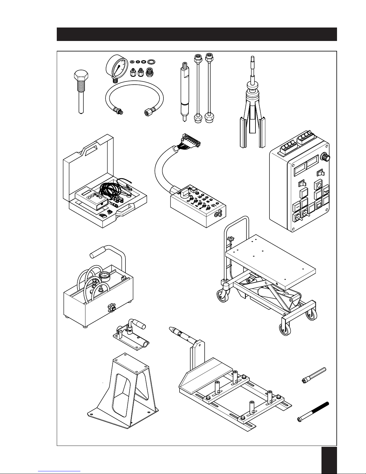
Special tools and workshop equipments
2
345 6 7
8 9 10 11 12 13 14 15
16 17
1
9
1
8
18 19 20 21
22 23 24 25
1
Page 20

Engine series 1 D . . (SUPRA)
Special tools and workshop equipments
1
1D . . / 03.06
Nr.
Bezeichnung
Verwendung
bei Typen
30-50 60-90
26
27
28
29
30
31
32
33
34
35
36
37
38
39
633 013 00
620 926 92
630 094 90
634 142 00
624 838 92
641 610 90
633 178 00
632 913 00
624 863 02
625 682 01
625 751 90
631 300 00
644 991 01
645 020 00
Forcing screw for centrif.-clutch
Oil pressure gauge 0... 6 bar
Test nozzle 400 bar / 5800 psi
Honing tool
Rev.-counter for fuel press.-pipe
Testbox for instrument box
Components testbox
High-pressure supply pump
Hydraulic lift trolley
Revolvable fixing - basic part
Console for revolvable fixing
Revolvable fixing - adaptor engine side
Socket wrench for lock nut
Punch for tab washer
xx
xx
xx
xx
xx
xx
xx
xx
xx
xx
xx
xx
xx
xx
Ident-Nr.
Page 21
1
1D . . / 03.06
Special tools and workshop equipments
26
27
1
2
3
5
6
4
0
28
29
31
30
#
*
ON
15
86
87a
50
87
STAR
- +
32
34
33
10
20
30
40
max. 750 kg
35
36
37
39
38
Page 22

1
1D . . / 03.06
Jointing material / Sealing and bonding agents
Sealing and bonding agents are available from HATZ for use in maintenance and/or repair works.
All items listed below may be ordered as individual spare parts.
Refer to appropriate spare parts list for ordering.
Application of sealing and bonding agents:
The letter coding in the drawings indicates which agents should be applied when fitting
the part refered to.
See the following list for decoding the material; this list is the same as already being
used with all other service literature including spare parts list.
A = 502 230 01 Loctite Activator 500 ml
B = 502 231 00 Loctite 573 50 ml
C = 502 232 00 Loctite 601 50 ml
D = 502 233 00 Loctite 221 50 ml
E = 502 234 00 Loctite 648 10 ml
F = 502 238 00 Technicoll 8058 750 g
+ 502 239 00 Technicoll 8367 750 g
G = 502 565 01 Loctite IS 407 20 g
H = 502 825 01 Silicon sealer 30 ml
J = 502 830 02 Anti-Seize compound 1000 g
K = 503 426 00 High-temp. lub.-grease 100 g
L = 502 566 00 Silicon sealer 100 g
M = 504 851 00 Polishing paste K 240 80 ml
Page 23

2
1D . . / 03.06
2. Additional equipment
Page 24

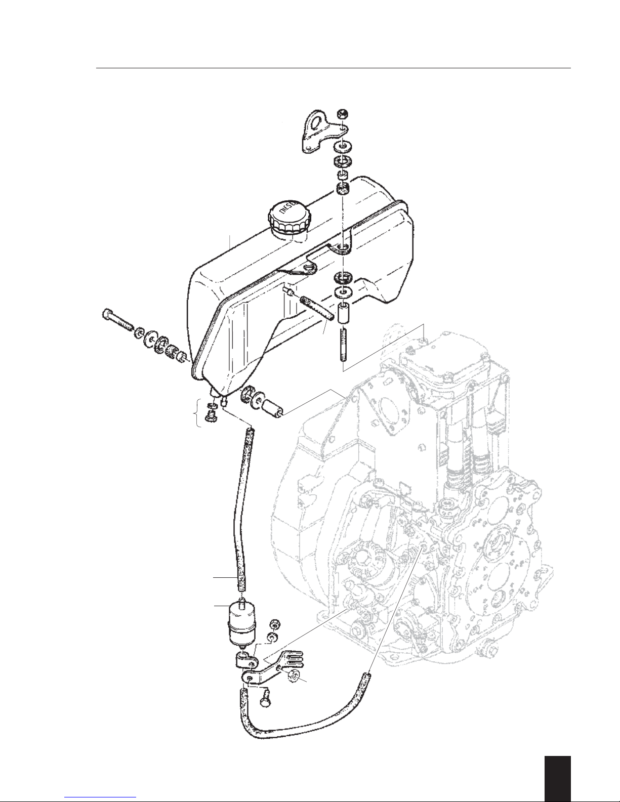
A 01.10 Fuel tank
–
Preparations: –
Dismantling:
– Loosen drain plug 1 and drain off fuel or
close off fuel supply pipe 2.
– Remove (pull off) fuel hoses 2...3 from
fuel filter and fuel tank.
– Unscrew respectively remove all retaining
components in question, including fuel
tank 4.
– Remove fuel filter 5 with retaining compo-
nents if necessary.
Inspection / repair:
– Visual inspection.
– Check fuel tank for cracks and/or any
other damage.
– Check all rubber parts for ageing etc.
Maintenance according to instruction book!
Assembly:
– Re-assemble and re-connect fuel tank 4
and fuel filter 5 as well as fuel hoses 2...3.
Tighten all retaining items uniformly to
obtain a stress free assembly of the fuel
tank.
– Remove clamp tool and/or tighten drain
plug 1.
2
1D . . / 03.06
A 01.00 Fuel
Page 25
A 01.00
A 01.10
2
1D . . / 03.06
4
3
2
5
1
Page 26

2
1D . . / 03.06
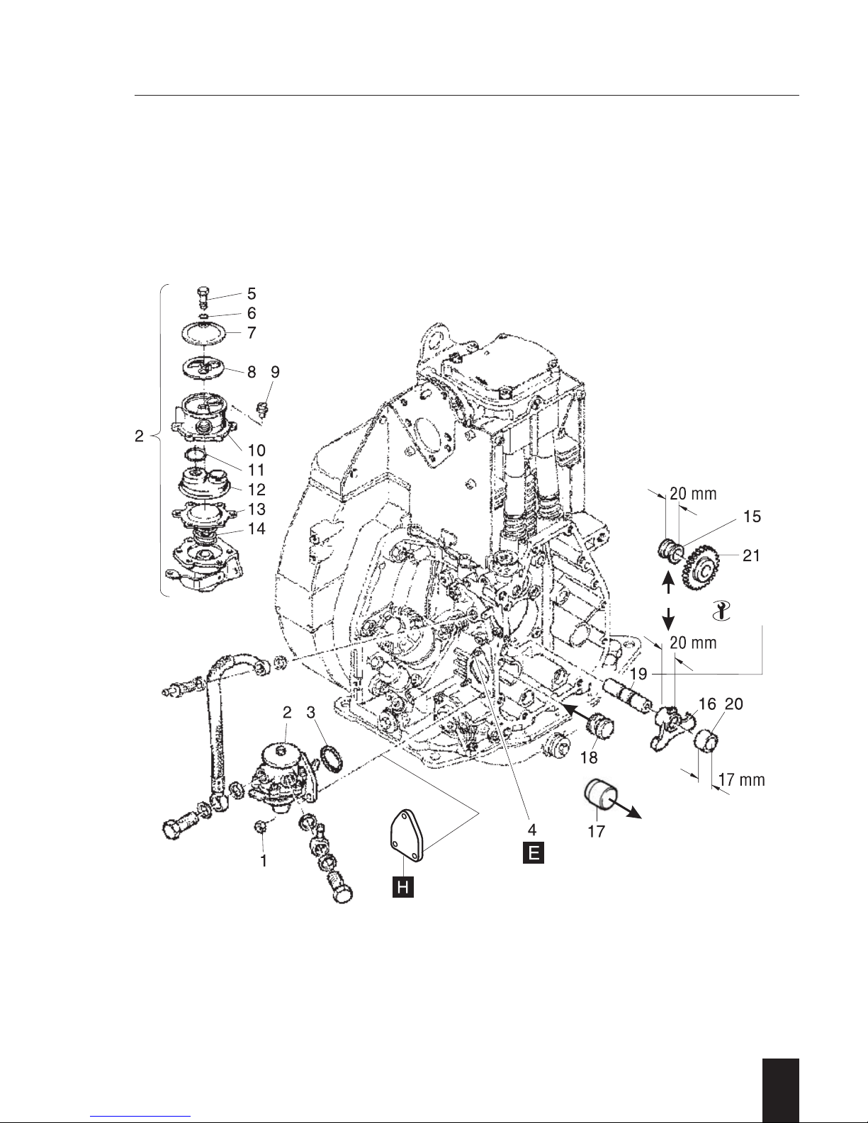
A 01.40 Fuel feed pumps
- 25 -
I. Fuel feed pump
General:
When connecting the fuel feed pump take
care for arrangement of suction and supply
hose.
Preparations:
– Disconnect fuel supply from fuel feed and
injection pump.
Dismantling:
– Remove in numerical sequence 1 ... 3.
NOTE:
When removing the upper nut, make sure
that the stud 4 does not turn in the crankcase as it serves as the anchor pin for the
governor lever retainer spring. If turning of
the stud cannot be avoided, remove the
spring from the pin. The front cover must be
removed to remove the spring.
Ref.: Chapt. M 11.00
Inspection / repair:
– Visual inspection.
For further repair proceed as follows:
– Remove in numerical sequence 5 ... 14.
Required only if irregularities such as poor
suction / pumping action i.e. contaminated
strainer or leaks have been noted.
– Check and replace all parts in question.
Assembly:
– Pre-assemble in reverse sequence 14...5.
– Assemble in reverse sequence 3 ... 1.
– Ensure actuating lever 16 is in bottom
position and „O“-Ring 3 remains in its
groove when assembling.
– After installation and a short test run,
check the fuel system for leaks.
II. Fuel feed pump drive
General:
Models Z/U/C
Bushing 15 is replaced by the actuating
lever 16.
Models S/T
Plug 17 is replaced by the plug 18 with
ring groove.
Preparations:
– Remove fuel feed pump.
– Remove timing cover.
Ref.: Chapt. M 11.00
Dismantling:
– Remove part 20/21 and lever 16.
– Remove shaft 19.
For removal use tool - 25 -
Plug 18 remains in crankcase.
Inspection / repair:
– Visual inspection.
– Check parts for wear and/or any other
damage.
Assembly:
– Assemble in reverse sequence .
– Press in shaft 19 to a protrusion of 52 ±
0,5 mm.
Extractor thread must face front!Models
Z/U/C
Ensure all gear timing marks match!
– Finish assembling.
A 01.00 Fuel
Page 27
2
1D . . / 03.06
A 01.00
A 01.40
25
Page 28

2
1D . . / 03.06
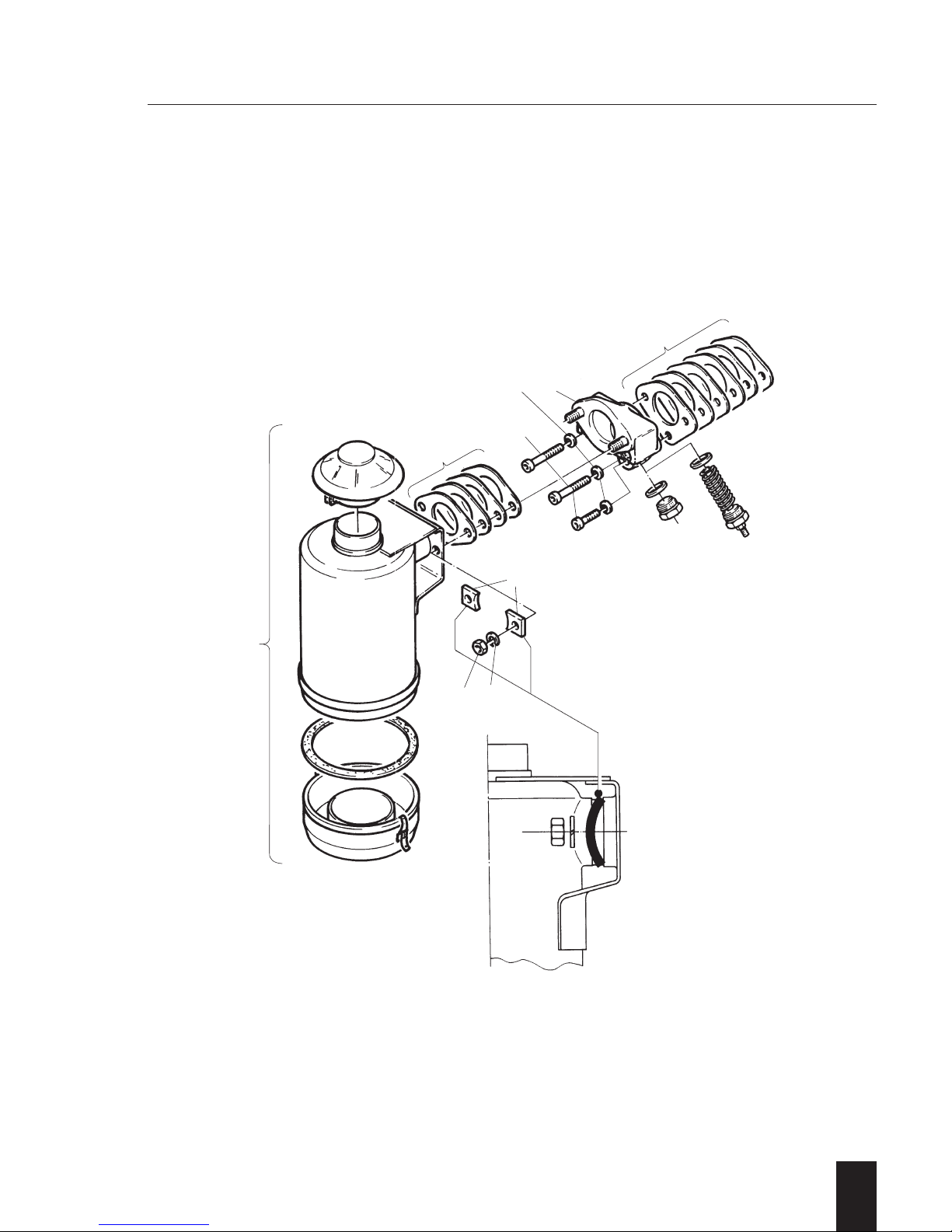
A 02.10 Oil bath air filters
–
General:
The oil bath air filter is fitted by means of an
intermediate flange which adapts from the
triangle-type flange at cylinder head to the
twin-screw flange of oil bath air filter. This
flange also holds the glow plug in case a
pre-heating system is fitted.
Preparations: –
Dismantling:
– Disconnect cable connection from glow
plug if fitted.
– Remove in numerical sequence 1...9.
Studs and Hex.-head screw plug or glow
plug may remain.
Don't tip oil bath air filter !
Inspection / repair:
– Visual inspection.
– Check air filter body for cracks and/or any
other damage.
Maintenance according to instruction book!
NOTE:
Never „repair“ an oil bath air filter by
welding/soldering etc.
It causes total damage to the part and may
lead to engine failure!
Assembly:
– Assemble in reverse sequence 9...1.
Ensure the correct amount of gaskets
are used and parts seal properly to
avoid infiltrated air.
When fixing the oil bath air filter take
care for correct position of kidneyshaped washers 3, convex side faces
retaining nuts 1.
– Reconnect cable connection to glow
plug if so fitted.
A 02.00 Combustion air
Page 29
2
1D . . / 03.06
A 02.00
A 02.10
78
6
3
12
4
9
5
Page 30

A 02.11 Dry type air filters
–
Version A 02.11.1
Fixation of filter element and cover by flat
washers and Hex.-nuts.
Preparations: –
Dismantling:
– Remove in numerical sequence 1...10.
Inspection/repair:
– Visual inspection.
– Check filter element 6 and sealing strip
around cover 3.
Maintenance according to instruction book!
Assembly:
– Assemble in reverse sequence 10...1.
Torque to specification!
NOTE:
Mind total length of bushing 4 and washer 5
respectively length of bushing 4 without
washer.
Take care for correct position of insulating
flange in between, correct amount of
gaskets and proper sealing of all parts to
avoid infiltrated air.
Conversion:
Possible to current standard in case all parts
in question become replaced.
2
1D . . / 03.06
Version A 02.11.2
Fixation of filter element separately by
retaining plate, flat washers and Hex.-nuts.
Preparations: –
Dismantling:
– Disconnect cable connection from
heater flange if so fitted.
– Remove in numerical sequence 1...12.
– If necessary dismantle cover retaining
screw to replace sealing sleeve (rubber)
between screw cap and cover.
Inspection / repair:
– Visual inspection.
– Check filter element 6 and sealing strip
around cover 1.
Maintenance according to instruction book!
Assembly:
– Assemble in reverse sequence 12...1.
Torque to specification!
NOTE:
Take care for correct position of insulating
flange in between, correct amount of
gaskets and proper sealing of all parts to
avoid infiltrated air.
– Reconnect cable connection to heater
flange if so fitted.
Conversion:
Possible to current standard in case all
parts in question become replaced.
A 02.00 Combustion air
Page 31

2
1D . . / 03.06
A 02.00
A 02.11
45
4
44
5
78
76.5
78
23 Nm
17 lb ft
23 Nm
17 lb ft
67.5 mm
64.7 mm
1D30 - 1D40
1D60 - 1D80
A 02.11.1
A 02.11.2
3
6
78
9
10
5
12
2
3
6
789
11
12
10
1
Page 32

A 02.11 Dry type air filters
–
Version A 02.11.3
Fixation of filter element by front cover
assembly.
Preparations: –
Dismantling:
– Disconnect cable connection from heater
flange if so fitted.
– Remove in numerical sequence 1...11.
– If necessary dismantle cover retaining
assembly to replace sealing sleeve (rubber) between centering and front cover.
Inspection / repair:
– Visual inspection.
– Check filter element 2 and sealing strip
around cover 1.
Maintenance according to instruction book!
Assembly:
– Assemble in reverse sequence 11...1.
Take care for correct position of insulating
flange in between, correct amount of
gaskets and proper sealing of all parts to
avoid infiltrated air.
– Reconnect cable connection to heater
flange if so fitted.
2
1D . . / 03.06
Version A 02.11.4 (A 1 D...)
Fixation of filter element separately by retaining plate, flat washers and Hex.-nuts.
Preparations: –
Dismantling
– Disconnect cable connection from hea-
ter flange if so fitted.
– Remove in numerical sequence 1...15.
Inspection / repair:
– Visual inspection.
– Check filter element 8, „O“-Ring around
retaining cover 11 and insulation plate 12.
Maintenance according to instruction book!
Assembly:
– Assemble in reverse sequence 15...1.
Take care for correct position of insulating flanges in between, correct amount
of gaskets and proper sealing of all
parts to avoid infiltrated air.
– Reconnect cable connection to heater
flange if so fitted.
A 02.00 Combustion air
Page 33

2
1D . . / 03.06
A 02.11.3
A 02.11.4
B
2
6
64.7
134
67
528
9
10
11
3
45
7
8910
11
12
13
15
14
A 02.00
A 02.11
Page 34

2
1D . . / 03.06
–
Preparations: –
Dismantling:
– Remove in numerical sequence 1...2.
– Remove in numerical sequence 3...6.
Ensure not to lose flap valve 6!
– Remove in numerical sequence 7...10.
Hose pulled off from banjo hose nipple
during removal.
Hose nipple connection 16 may remain.
1 D 60 - 80 - 81 only:
– Snip cable strap 11.
– Remove in numerical sequence
10/12...15.
Parts may remain as a unit.
Inspection / repair:
– Visual inspection.
– Check maintenance indicator by sucking
and releasing at the end of hose or adapter for indication.
Sucking = indicator „CLOSED“
(green section ring not visible)
Release = indicator „OPEN“
(green section ring visible).
–Check all rubber parts for material
ageing etc.
–Check all parts in question for proper fit.
Maintenance according to instruction book!
Assembly:
– Assemble in reverse sequence 15...10.
1 D 60 - 80 - 81 only!
– Cable strap remains loose.
– Connect hose 10 to hose nipple
connection and assemble parts 9...7.
– Put flap valve 6 onto pin location of
retaining bracket 5.
– Assemble in reverse sequence 5...3.
Ensure flap valve remains in position
during assembly!
– Check function of flap valve in connec-
tion with maintenance indicator as follows:
– Press indicator cap.
Cap has to remain for a short term in
„CLOSED“ position.
Green section ring not visible!
NOTE:
A minimum time of 3 s between
„CLOSED“ and „OPEN“ has to be
obtained.
– Lift flap valve.
Cap has to come to „OPEN“ position.
Green section ring visible!
Ensure the indicator reacts as described.
If not, check seating position in housing
or replace flap valve.
– Assemble in reverse sequence 2...1.
1 D 60 - 80 - 81 only:
– Tighten cable strap.
A 02.00 Combustion air
A 02.13 Service indicators; vacuum gauges
Page 35

2
1D . . / 03.06
A 02.00
A02.13
Page 36

2
1D . . / 03.06
A 02.20 Pre-cleaners; cyclons
–
Version A 02.20.1
Cyclon fitted at bottom side inlet port.
Front inlet port and through holes plugged.
Preparations: –
Dismantling:
– Loosen hose clip and remove cyclon 1.
Inspection / repair:
– Visual inspection.
– Check closing plugs for tightness.
Maintenance according to instruction book!
Don't use oily cleansers.
Assembly:
Place cyclon 1 and tighten hose clip.
Version A 02.20.2
Cyclon fitted to front side inlet port.
Bottom inlet port closed.
Preparations: –
Dismantling:
– Remove front cover 1 including cyclon
system.Closing cap at bottom side
remains.
– Remove in numerical sequence 2...5.
Inspection / repair:
– Visual inspection.
– Check rubber elbow for material ageing,
replace if necessary.
Maintenance according to instruction book!
Don't use oily cleansers.
Assembly:
– Assemble in reverse sequence 5...1.
A 02.00 Combustion air
Page 37

2
1D . . / 03.06
A 02.20.1 A 02.20.2
1
45 1
32
A 02.00
A 02.20
Page 38

2
1D . . / 03.06
- 2 -
Version A 03.12.1
Exhaust silencer fitted in connection with
studs, flat washers and hex.-nuts.
Version A 03.12.2
Fixation by Allen screws.
Preparations:
– Remove protection guard if so fitted.
Dismantling:
Version A 03.12.1
– Remove in numerical sequence 1...5.
Bushings 4 are fitted only in connection
with an exhaust silencer with recessed
bores to prevent the silencer getting loose.
Version A 03.12.2
– Remove in numerical sequence 1...3.
For removal use tool - 2 -
Inspection / repair:
– Visual inspection.
– Check exhaust silencer for possible cracks
and/or any other damage.
Assembly:
– Assemble in reverse sequence.
Apply lubricant as specified!
Torque to specification!
Ensure gasket-kit is fitted in correct sequence i.e. the creased gaskets face towards
exhaust silencer.
– Assemble protection guard if so fitted.
Conversion:
Possible to current standard.
Protection guard
General:
The fixation of the guard has been modified to avoid breaks around the fixation
due to excessive vibrations.
Preparations:–
Dismantling:
– Remove in numerical sequence 1...3/4.
Inspection / repair:
– Visual inspection.
– Check guard around fixation for breakage.
Assembly:
– Assemble in reverse sequence 4/3...1.
Use anti-seize compound as specified.
Ensure the concave side of the curved
washers 4 face towards guard 3.
A 03.00 Exhausts
A 03.12. Exhaust-silencers, high performance / Protection guard
Page 39

2
1D . . / 03.06
A 03.12.1
A 12.30.1
A 03.12.2
A 12.30.2
53
21
43 21
23 Nm
17 lb ft
5
3
1
2
1
2
4
33
4
1
2
4
4
3
2
A 03.00
A 03.12
Page 40

2
1D . . / 03.06
–
Version A 04.10.1
Standard starting handle:
Replaceable at any time by a safety starting
handle if required or specified.
ATTENTION !
Take care, a worn shaft or broken handle
can cause serious injuries.
Preparations: –
Dismantling: –
Inspection / repair:
– Visual inspection.
– Check shaft 1 and handle 2 for wear
and/or any other damage.Handle 2 can be
replaced by removing and replacing snap
ring 3.
In case shaft 1 is worn replace complete
starting handle.
A 04.00 Start mechanical / pneumatic
A 04.10 Starting handles without supports
Page 41

2
1D . . / 03.06
A 04.10.1
A 04.10.2
47
8
15
14 13
12
11
10
9
6
5
16
1521
3
A
1
23
A 04.00
A 04.10
Page 42

2
1D . . / 03.06
–
Version A 04.10.2
Anti-kick-back starting handle, specified as
type A for 1 D.. S/Z/C engines.
ATTENTION !
Take care, a worn shaft or broken handle
can cause serious injuries.
Preparations: –
Dismantling:
– Remove in numerical sequence 1...3.
– Remove Allen screws 4 and cover 5.
Remove cover carefully to avoid plate
spring 11 jumping out.
Risk of injury !
– Remove in numerical sequence 6...10.
– Hold leg spring 13 firmly down to avoid
release of spring tension.
– Pull plate spring 11 off its pin location and
out of the hook shaped part of the leg
spring 13.
– Release spring tension of leg spring using
a screw driver or similar tool.
Risk of injury!
– Remove in numerical sequence 12...13.
Housing 14 remains with all fixed parts.
Inspection / repair:
– Visual inspection.
If cover 5 and housing 14 are worn or
damaged, use a new starting handle.
Bearing bushings 15 and oil seal 16 can
be replaced.
– Check handle 7 for wear and/or damage
concerning teeth and/or handle.
Take care not to damage teeth when a
new end plug 8 becomes fitted.
End plug has to be existent !
– Check conditions of bushing and plate
spring on lever 9.
– Check condition of plate spring 11 and
leg spring 13.
– Check starting handle shaft 3 for wear
and/or any other damage.
Replace worn shaft and hardware if
necessary.
Assembly:
– Assemble in reverse sequence 13...12.
Apply locking agent as specified!
Ensure leg spring is not squeezed,
straight end catches groove in location
pin.
– Force leg spring 13 against spring ten-
sion until hook shaped part catches end
position at inside of through hole eye.
– Hold leg spring 13 firmly down to avoid
release of spring tension.
– Place plate spring 11 into hook shaped
part of leg spring 13 respectively onto
location pin.
Rolled end of plate spring faces centre
of housing.
– Put lever 9 onto location bolt.
– Place handle 7 / 8 onto handle shaft.
Check handle-teeth, lever and plate
springs for free moving.
– Apply approx. 50g/1.8 oz. of grease as
specified into cavity of housing 14
respectively over all mechanical parts.
– Place gasket 6 and cover 5 carefully
over handle 7 onto housing 14.
– Place and tighten Allen screws 4 cross-
wise and uniformly.
– Assemble in reverse sequence 3...1.
– Check complete unit for proper function.
A 04.00 Start mechanical / pneumatic
A 04.10 Starting handles without supports
Page 43

2
1D . . / 03.06
A 04.10.1
A 04.10.2
47
8
15
14 13
12
11
10
9
6
5
16
1521
3
A
1
23
A 04.00
A 04.10
Page 44

2
1D . . / 03.06
–
General:
Version A 04.11.1
Part without replaceable bushing.
Version A 04.11.2
Part with replaceable bushing.
ATTENTION !
Take care, a worn guiding shell can cause
serious injuries.
Preparations: –
Dismantling:
– Remove in numerical sequence 1...3/4.
NOTE:
Engines working under extremly dusty conditions should be equipped with a protection
plate 4 which avoids access of dust to the
contact area of camshaft seal ring.
Inspection / repair:
– Visual inspection.
– Check bore for wear and/or any other
damage.
Version A 04.11.1
– In case bore is worn (oval) replace
guiding shell.
Version A 04.11.2
– In case bore/bushing is worn (oval)
replace guiding bushing 5.
Assembly:
– Assemble in reverse sequence 4/3...1.
Apply locking agent as specified!
Use starting handle to align guiding shell
before tightening Allen screws.
- 25 -
General:
Version A 04.12.1
Part is bonded into camshaft.
Version A 04.12.2
Parts fitted loose in camshaft.
ATTENTION !
Take care, a worn or damaged cranking
claw can cause serious injuries.
Preparations:
– Remove guiding support if so fitted.
Dismantling:
Version A 04.12.1
– Weld (spots and arc-welding only) M8
nut onto crank jaw.
For removal of crank jaw use tool - 25 -
Protect area around camshaft to avoid
any damage.
Version A 04.12.2
– Remove parts (pull) by hand in numerical
sequence 1...3.
Inspection / repair:
– Visual inspection.
Replace crank jaw in case of wear.
Assembly:
Version A 04.12.1
– Apply high strenght locking agent
around location pin and insert (push)
crank claw firmly in.
Version A 04.12.2
– Bring location groove in camshaft to
TOP-position.
– Put location pin 3 onto crank jaw 2.
– Insert parts together into bore
– Place and tighten Allen screw 1.
Apply locking agent as specified!
– Assemble guiding support if so fitted.
A 04.00 Start mechanical / pneumatic
A 04.11 Starting handle supports A 04.12 Cranking claws
Page 45

2
1D . . / 03.06
4321
421
321
25
A 04.11.1
A 04.11.2
A 04.12.1
A 04.12.2
3
5
A 04.00
A 04.11
A 04.12
Page 46

A 04.30 Rope starts
–
General:
Recoil starters available respectively fitted
as additional equipment in connections with
engines as follows:
Preparations: –
Dismantling:
– Remove in numerical sequence 1...2 from
respective engine flange.
– Pull knot / rope 3 with snipe nosed pliers
from handle 4 and untie.
– Allow rope pulley 5 to retract slowly until
recoil spring 6 is unwound.
Rope guide 13 and closing screw 14 may
remain.
– Remove in numerical sequence 7...12.
Brake spring 10 may remain.
– Remove rope pulley 5 carefully from recoil
spring 6 respectively housing.
NOTE:
To prevent the recoil spring from uncoiling,
rotate rope pulley back and forth to disengage inner spring eye and carefully lift out of
housing.
Recoil spring needs not to be removed from
housing, unless it is broken.
To remove recoil spring 6 take housing in
both hands, open side down and hit housing
on work bench or other flat surface.
Spring will drop out.
– Remove rope 3 from rope pulley 5.
2
1D . . / 03.06
Inspection / repair:
– Visual inspection.
– Check all parts in question, inclusive
driving elements 15 for wear and / or
any other damage.
Assembly:
It is of utmost importance to follow the
details as specified to obtain the correct
assembly as far as engine models in connection with direction of rotation is concerned.
With unwound recoil spring out of housing:
– Wind recoil spring 6 into housing.
With new recoil spring - prewound:
– Place recoil spring in housing and push
down into housing. Remove retaining
wire.
NOTE:
The outer spring eye must be properly
hooked around the retaining tab.
The clearance required between inner
spring eye and rope pulley shaft has to be
obtained as specified.
If necessary, rebend spring eye.
Apply high-temp. lub.-grease as specified
over all mechanical parts during assembly.
– Slide rope 3 through hole in rope pulley
5 and wind rope around pulley accor-
ding to engine model.
– Fit rope pulley together with rope 3 and
carefully rotate it back and forth until it
engages in the inner spring eye of the
recoil spring 6.
– Fit long end of torsion spring 12 into
hole of rope pulley 5 as specified
according to engine model, pushing it
over pawl guide.
A 04.00 Start mechanical / pneumatic
Engine types 1 D 30 - 31 - 35 - 40 - 41
models position
direction
of rotation
execution
of housing
S/Z
Flywheel
side
counter
clockwise
closed
T/U clockwise open
Page 47

2
1D . . / 03.06
4mm
4mm
13
1
14
4
3
5
12 11
10 9
87
6
2
2
15
13 1
4
3
65
12 11
10 9
8
7
S/Z
T/U
A 04.00
A 04.30
Page 48

A 04.30 Rope starts
– Slip pawl 11 according to engine model
over pawl guide.
Short end of torsion spring 11 must fit into
groove of pawl.
– Push down brake disk 9 with brake
spring 10 as specified according to engine
model onto rope pulley shaft.
– Place and tighten retaining items 8...7.
Apply locking agent as specified !
– Rotate rope pulley 5 as specified 3 - 4
turns against the recoil spring tension and
hold firm.
– Slide rope 3 through the rope guide 13 in
the housing respectively through handle 4
and tie knot.
Slowly return handle.
– Check recoil starter for proper function.
If the recoil starter has been properly
assembled, the pawl must move outward
when rope is pulled.
2
1D . . / 03.06
A 04.00 Start mechanical / pneumatic
Page 49

2
1D . . / 03.06
4mm
4mm
13
1
14
4
3
5
12 11
10 9
87
6
2
2
15
13 1
4
3
65
12 11
10 9
8
7
S/Z
T/U
A 04.00
A 04.30
Page 50

General:
The execution of electrical equipment
depends on voltage (12 V or 24 V) as well
as the direction of rotation.
Different ring gears, starter motors, coils
and magnet segments are applied.
2
1D . . / 03.06
A 05.00 Start electrical
Page 51

Page 52

2
1D . . / 03.06
A 05.20 Starter motors
- 17 -
General:
Starter motors are different in construction
as well as voltage and direction of rotation is
concerned.
It is of utmost importance not to combine
parts from different construction or version.
Preparations:
– Disconnect battery in sequence - / +
– Disconnect cable connections as necessary,
respectively remove retaining plate with
voltage regulator depending on kind of
equipment.
Dismantling:
– Remove in numerical sequence 1...6.
Studs 7 may remain.
For removal use tool - 17 -
Inspection / repairs:
– Visual inspection.
– Check bushing and pinion for wear and/or
any other damage.
– Check pinion for free movement on shaft.
NOTE:
Repairs or adjustments in connection with
the starter motor should be carried out by a
HATZ-Distributor or any other authorized
workshop.
Assembly:
– Assemble in reverse sequence 6...1.
– Reassemble respectively reconnect elec-
trical system as dismantled before.
– Reconnect battery in sequence +/-
– Check (start) electrical system for proper
function.
A 05.00 Start electrical
Page 53

2
1D . . / 03.06
17
21
4
53
76
A 05.00
A 05.20
Page 54

2
1D . . / 03.06
–
General:
It is recommended to always check the
alternator for degree of function before any
disassembly.
Ref.: Section 4
Preparations:
– Remove flywheel (M 17.00).
Version A 05.40.1
The magnet segments are located on the
flywheel by means of centering/roll pins.
Version A 05.40.2
The magnet segments are located on the
flywheel by means of a machined location
ring groove.
Version A 05.40.3
The magnet segments are substituted by a
magnet ring.
Dismantling:
– Remove in numerical sequence
Inspection / repair:
– Check magnet segments for wear or any
other damage.
Assembly:
– Assemble in reverse sequence
Torque to specification!
A 05.00 Start electrical
A 05.40 Alternator / Magnet segments
Page 55

2
1D . . / 03.06
A 05.40.3
A 05.40.1 A 05.40.2
2.8 Nm
2.1 lb ft
1
2
3
4
2
1
1
2
A 05.00
A 05.40
Page 56

2
1D . . / 03.06
A 05.41 Alternator / Coils
–
Version A 05.41.1
Open coils fixed to the crankcase.
Fixation and adjustment of air gap is done
by spacers.
Preparations:
– Remove flywheel and housing.
Dismantling:
– Disconnect electrical system.
– Remove in numerical sequence 1...5.
Inspection / repair:
– Visual inspection.
– Check coils for wear and/or any other
damage.
Assembly:
– Assemble in reverse sequence 4...1.
Without spacers 5 and retaining nuts 1
loose.
Adjustment:
– Assemble flywheel.
NOTE:
Flywheel tight, not torqued.
– Push flywheel towards governor side or
even better put engine onto flywheel to
eliminate the end float.
– Measure gap between coils and magnet
segments.
Use feeler gauge.
– Keep spacers as required next to the
corresponding coil to obtain air gap as
specified.
– Remove flywheel.
– Place spacers as required between
crankcase and corresponding coils.
– Tighten Hex.-nuts uniformly.
– Finish assembling.
A 05.00 Start electrical
Page 57

2
1D . . / 03.06
A 05.41.1
45
321
min 0.7 mm
5
A 05.00
A 05.41
Page 58

2
1D . . / 03.06
A 05.41 Alternator / Coils
–
Version A 05.41.2 (1D 60-80)
Coils fitted to support and fixed on bottom
side of crankcase.
Fixation and adjustment of air gap by
moving the complete unit in longitudinal
slots.
Preparations:
– Remove flywheel and housing.
Dismantling:
– Disconnect electrical system.
– Remove in numerical sequence 1...4.
If necessary separate coils and support.
Inspection / repair:
– Visual inspection.
– Check coils for wear and/or any other
damage.
Assembly:
– Assemble in reverse sequence 4...1.
NOTE:
Push unit 3 as far as possible in direction to
crankcase and tighten Hex.-nuts 1 tempora-
rily.
Adjustment:
– Assemble flywheel.
– Put engine onto flywheel to eliminate the
end float.
– Place feeler gauges between coils and
flywheel-magnet segments to obtain air
gap as specified.
– Release retaining nuts 1.
Allow complete unit 3 to drop down onto
feeler gauges.
– Tighten Hex.-nuts uniformly.
– Finish assembling.
A 05.00 Start electrical
Page 59

2
1D . . / 03.06
A 05.41.2
min 0.7 mm
4
2
1
3
A 05.00
A 05.41
Page 60

2
1D . . / 03.06
A 05.41 Alternator / Coils
–
Version A 05.41.3
Coil encapsulated and fitted to crankcase.
Fixation and adjustment of air gap by
moving the coil in longitudinal slots.
Preparations:
– Remove flywheel.
1 D 30 - 31 - 35 - 40 - 41 - 50 only !
– Remove protection guard 1.
Dismantling:
– Disconnect electrical system.
– Remove in numerical sequence 2...4.
Inspection / repair:
– Visual inspection.
– Check coil for wear and/or any other
damage.
Assembly:
– Assemble in reverse sequence 4...2.
– Push coil 4 as far as possible in direction
to crankcase and tighten Allen screws
temporarily.
Adjustment:
– Assemble flywheel.
1 D 30 - 31 - 35 - 40 - 41 - 50 only !
– Push flywheel towards crankcase.
Ensure flywheel remains in position !
– Remove grub screw or plug 5.
– Place feeler gauge between coil and
flywheel-magnet segments to obtain air
gap as specified.
– Release Allen screws 2.
– Push coil towards flywheel against
feeler gauge.
Ensure flywheel remains in position !
– Tighten Allen screws uniformly.
– Reassemble protection guard 1 and
grub screw or plug 5.
– Reconnect electrical system.
Alternator 12 V “high output” 350 W
(1D60 ... 90):
On this alternator the gap between the
coil and the magnet ring must be adjusted
to 1.2 mm . Otherwise the max current of
25 A will be exceeded and the voltage
regulator switch could be damaged.
A 05.00 Start electrical
Page 61

2
1D . . / 03.06
A 05.00
A 05.41
Page 62

2
1D . . / 03.06
A 05.80 Ring gears
–
General:
Ring gears are different in pitch as well as
direction of rotation is concerned.
It is of utmost importance not to combine
parts with incorrect pitch or rotation.
Preparations:
– Remove flywheel (M 17.00).
Inspection / repair:
– Check part for broken teeth and/or other
damage.
Burrs can be filed down to a certain
extent.
Dismantling:
– Check condition of ring gear before removal.
In case ring gear has to be removed proceed as follows:
– Heat starter ring gear rapidly (gas torch)
and detach ring from flywheel.
Another way is to drill and chisel the ring
gear open.
Assembly:
– Heat ring gear properly around its diame-
ter and shrink fit ring gear onto flywheel.
NOTE:
Take care for correct position of chamfered
side facing towards starter motor and proper
seat on flywheel.
– Finish assembling.
A 05.00 Start electrical
Page 63

2
1D . . / 03.06
°C
°F
300
150
S/Z/C
T/U
1
A 05.00
A 05.80
Page 64

2
1D . . / 03.06
A 07.20 Lub.-oil filters, strainers
–
General:
Retro-fit of lub.-oil filter is possible at any
time and requires removing of closing cover
only.
Version A 07.20.1
Version A 07.20.2
Preperations: –
Dismantling:
– Remove in numerical sequence 1...6.
Version A 07.20.2:
Spring in filter housing 5 remains.
Inspection / repair:
– Visual inspection.
– Check oil filter element 2 and rectangular
rings 6.
Maintenance according to instruction book.
Assembly:
– Assemble in reverse sequence 6...1.
Apply High-temp. lub. -grease as speci-
fied!
– Ensure rectangular ring 6 at bottom side
remains in position during assembly.
– Place and tighten Allen screws crosswise
and uniformly.
A 07.00 Lubrication oil
Page 65

2
1D . . / 03.06
A 07.20.1
A 07.20.2
1
1
34
34
625
6
6
5
62
A 07.00
A 07.20
Page 66

2
1D . . / 03.06
A 07.30 Oil sumps
–
General:
Additional oil sump may be used to obtain
higher oil change intervals.
Depending on the oil quantity as required
– different oil pans
– suctions strainers and adaptors
– spacer rings for the oil pan
– dipsticks of different length may be fitted.
Take care not to interchange these components by mistake during a repair and / or
conversion job.
Assembly:
Ref.: Chapt. M 01.30
In addition two of spring washers and elastic
washers are fitted between suction sieve
and oil intake tube.
Apply sealing agent as specified !
A 07.00 Lubrication oil
Page 67

2
1D . . / 03.06
60 25 58 204
60 + 60 25 118 285
40 25 58 204
40+40
25 98 225
1D30-31-35-40-41
1D60-80-81
2.8 l
4.4 l
3.2 l
4.5 l
mm mm mm mm
mm mm mm mm
A 07.00
A 07.30
Page 68

2
1D . . / 03.06
A 09.60 Low idle speed stabilization
- 5 - 30 -
General:
Several engine applications require a very
precise speed governing also in the range of
low idle, for example engines with hydraulic
pumps in cold condition.
For this case the low idle speed stabilization
is available.
Function:
– The main governor spring is approx. 1 mm
shorter than the standard one so that it is
deactivated at engine speeds below
1000 rpm.
– Governor lever 1 is working over the full
speed range.
– The retainer spring 2 is connected to an
adjustable lever 3 and works as governor
spring at the speed range below 1000 rpm.
– The stabilization spring 4 is fitted to stabi-
lize the overreaction of the governor lever
when the speed control lever is turned
back into „low“ position.
It can be adjusted by the eccentric disk 5.
– The standard stop screw 6 is turned back
a few threads to ensure it is out of function.
Basic adjustment:
– Turn screw II so that eccentric disc 5 is
facing towards timing cover.
Flat surface at outer end of screw II is now
parallel with timing cover.
– Turn screw III into a position that the
stabilization spring 4 is slightly tuching
the eccentric disc 5.
This is the final position.
Lock screw III by tightening the counter
nut.
– Turn screw II approx. 180° counter clock-
wise (Stabilization spring 4 now is forced
as far as possible towards crankcase).
– Turn screw I so that lever 3 is facing
vertical downwards (pin 7 is also in a
vertical position).
Fine tuning:
(with engine running)
– Connect rev. counter - 30 -
– Set low idle speed to approx. 600 rpm.
If engine speed drops too far and
engine stops, than turn screw I in direction „+“ (counter clockwise).
If such low speed can not be obtained
turn screw I in direction „-“ (clockwise)
or turn screw 6 back for some threads.
– Turn screw I slightly in counter clockwi-
se direction until the aspired speed is
reached and lock screw with counter nut.
– Turn screw II clockwise (use tool - 5 - )
until the stabilizing spring is just
touching the governor lever. This is indicated by an additional rise of the
engine speed (max. 5 rpm).
Lock screw by tightening the counter nut.
– Finally seal all adjustment screws with
sealing wax.
A 09.00 Speed controls
Page 69

2
1D . . / 03.06
I
II
III
I
II
III
I
II
III
7
5
3
2
1
4
6
29.5
30.5
5
A 09.00
A 09.60
Page 70

2
1D . . / 03.06
A 11.10 Stop devices
–
Version A 11.10.1
Stop lever S/Z/T/U
Preparations: –
Dismantling:
– Remove in numerical sequence 1...4.
– Remove timing cover (M 11.00).
– Remove lever 5.
Bushing 6 may remain
Inspection / repair:
– Check lever 5 and bushing 6 for wear or
any other damage.
Assembly:
– Press bushing 6 firmly in (if necessary).
Apply high strength locking agent as
specified !
– Bring bushing 6 to a position to have the
lever 5 just in the centre of the respective
contact face of the governor lever.
– Assemble in reverse sequence 5...1.
NOTE:
Hold stop lever 3 against tightening force of
Hex.-nut 1 to avoid excessive stress on
governor lever.
– Finish assembling.
Version A 11.10.2
Stop lever C.
Preparations: –
Dismantling:
– Remove in numerical sequence 1...10.
For further repair remove capsule parts
as required to have access to standard
engine respectively to bush 11 and lever 12.
Inspection / Repair:
– Check lever 5 and bushing 6 for wear or
any other damage.
Assembly:
– Assemble in reverse sequence.
NOTE:
Hold lever 9 against tightening force of
shaft 8 to avoid excessive stress on governor lever.
Hold lever 3 against tightening force of
Hex.-nut 1 to avoid excessive stress on
linkage and/or governor lever.
A 11.00 Remote engine controls
Page 71

2
1D . . / 03.06
A 11.10.1
A 11.10.2
5
12
12346
123
6
5
7
5
11
10
9
8
4
=
=
A 11.00
A 11.10
Page 72

A 11.30 Auto. Shut-off device
–
General:
In order to avoid serious engine damage
due to insufficient lubrication (e.g. excess
tilting of engine), the mechanical shut-off
device was developed.
Function:
If the oil-pressure is too low, the fuel feed
and fuel return is shut off by a valve.
- Opening pressure on cold engine 0.4
bar
- Shut-off reaction pressure approximately
1.0 bar at 3000 rpm
- Idle speed of 800 rpm admissible up to
oil level "min".
- Once fuel system has run totally dry,
relief lever must be activated for approx.
15 seconds for bleeding after tank filling.
In case of (repair) work at the shut-off
device, the correct connection of fuel
pipes (flow direction) must be assured.
1 = inlet from fuel filter (tank)
2 = inlet to injection pump
3 = return from injection pump
4 = return to tank
2
1D . . / 03.06
A 11.00 Remote engine controls
Page 73

2
1D . . / 03.06
Run:
Feed Return
Relief
lever
Relief
lever
A 11.00
A 11.30
Page 74

2
1D . . / 03.06
A 15.20 Adaptor housings
–
Preparations:
– Remove starter motor if so fitted.
Dismantling:
– Remove in numerical sequence 1...7
depending on kind of application.
Parting sheet 9 may remain.
NOTE:
Removal of parting sheet requires dismantling of flywheel 8.
Inspection / repair:
– Visual inspection.
– Check housing for cracks or any other
damage.
Assembly:
– Assemble in reverse sequence 9...1.
– Assemble starter motor if so fitted.
A 15.00 Housings - flanges - adaptors
Page 75

2
1D . . / 03.06
1
3
954
54654
78
21
A 15.00
A 15.20
Page 76

Page 77

3
1D . . / 03.06
3. Basic engine
Page 78

Page 79

3
1D . . / 03.06
M - Basic engine
M-Disassembly cross reference scheme
Page 80

- 9 - 13
Preparations:
Ref.: M-Disassembly cross reference
scheme.
Oil spray nozzle
– Install and screw nozzle 3 firmly in place
so oil spray will be directed down directly
on the camshaft.
Apply high strength locking agent E.
Clock-wise engines (version T/U) are
equipped with an additional oil spray nozzle in the timing cover. It points to the middle of the camshaft bearing bore (view to
inside of timing cover).
Main bearing
Dismantling:
– Check main bearing before removal.
– Remove main bearing 1 by pushing it in-
ward toward crankcase.
For removal use tool - 9 -
Inspection / repair:
– Visual inspection.
Inspection should be carried out before
removal !
All dimensions measured in fitted conditionat 20±10° C / 68±18° F.
3
1D . . / 03.06
Assembly:
– Apply locking agent E to bearing 1 and
press firmly in place. For assembly use
tool - 9 -
Ensure lubrication passages align.
Position in crankcase as specified !
1 D 60 - 80 - 81 - 90:
Slotted lubrication passage has to align
with the main gallery at the bottom side of
crankcase. Check the small lubrication
bore on top for free passage.
Camshaft bearing
Dismantling:
– Check condition of bearing bushing before
removal.
– Remove bearing bushing 2 by pushing it
inward toward crankcase.
For removal use tool - 13 -
1 D 60 - 80 - 81 - 90:
– Push bearing approximately half way
into the crankcase.
Be careful not to damage bore or
crankcase.
– Destroy bearing bushing to remove.
Assembly:
– Install and press bearing bushing 2 firm-
ly in place.
For assembly use tool - 13 -
Make sure lubrication passages align.
Position in crankcase as specified !
M 01.00 Crankcase
M 01.10 Crankcase, nozzle and bearings
Page 81

3
1D . . / 03.06
M 01.00
M 01.10
Page 82

M 01.11 Plugs
Variant I
up to series no.:
1 D 30.15 A 1 D 35.13
1 D 31.13 A 1 D 40.12
1 D 40.16 A 1 D 41.11
1 D 41.13
1 D 60.22 1 D 81.15
1 D 80.21 1 D 90.10
In case no fuel feed pump is fitted plug 1
without ring groove has to be fitted on
both sides. In case a fuel feed pump is
fitted plug 2 with ring groove has to be
used on the operator side instead of plug
1 to guarantee lubrication of rocker arm.
Assembly:
– Push in plugs (chamfer 2 x 45° timing
cover direction) firmly until flush with
crankcase inside wall
3
1D . . / 03.06
Variant II
from series no. on:
1 D 30.16 1 D 40.17
1 D 31.14 1 D 41.14
1 D 60.23 1 D 81.16
1 D 80.22 1 D 90.11
1 D 90 V/W.10
(modified lubrication oil duct)
In case no fuel feed pump is fitted plug 2
with ring groove has to be fitted on ex-
haust side. Plug 1 without ring groove has
to be fitted on operation side.
In case fuel feed pump is fitted plug 2 has
to be used on both sides with ring groove.
1 D 90 V:
On both sides, plug 2 with ring groove has
to be fitted.
In addition, the axle with nozzle 4 and
bushes 5 and 6 are mounted.
Axle 4 is fitted in such a way that the spray
nozzle points to the middle of the
camshaft bearing bore.
Additionally, in both cases plug 3 (with
extractor thread towards timing cover) has
to be fitted in the bore for intermediate
axle.
M 01.00 Crankcase
For versions without add. counter balance the bores for the balancer shafts are closed
with plugs to obtain full oil pressure.
Page 83

3
1D . . / 03.06
1
2
1
Variante II
Variante I
2
2
3
2
1
2
4
5
6
M 01.00
M 01.11
Page 84

3
1D . . / 03.06
- 25 -
Cam followers
General:
Models S/Z/C = anti-clockwise rotation
Cam followers symmetrically arranged.
Models T/U = clockwise rotation
Cam followers asymmetrically arranged.
Besides the normal cam follower 3 for the
inlet valve a separate cam follower 5 for
the exhaust valve is fitted onto the cam follower bracket 6.
The cam follower bracket as well as the
thrust plate are fitted together to the
crankcase by Allen screws.
1 D 30 - 31 - 35 - 40 - 41 only !
A spacer plate 7 is fitted in addition between the cam follower bracket 6 and the
thrust plate 9.
Preparations:
Ref.: M-Disassembly cross reference
scheme.
Dismantling:
– Remove in numerical sequence 1...4/5.
For removal of part 2 use tool - 25 -
Inspection / repair:
– Check all parts in question for wear
and/or any other damage.
Assembly:
– Assemble in reverse sequence 5/4...1.
Apply locking agent as specified !
Torque to specification !
M 01.00 Crankcase
M 01.20 Crankshaft-thrustplate and cam followers
Page 85

3
1D . . / 03.06
M 01.00
M 01.20
9 8
I
M 8
0.10 - 0.40 mm
3
3
2
2
1
25
25
25
25
3
2
1
9 7 6
8
8 5
2
1
10
10
M9
M8
M8
M6
M6
10.9
10.9
8.8
10.9
8.8
40
35
24
14
11
30
26
18
10
8
8
1
Nm
lb ft
Pos.
T / U
S / Z / C
3.5 mm
10
9 8
9 8
0.9 mm
II
M 8
1.05 mm
1.20 mm
10
M 9
III
M 6
4
4
4
1D90 V/W:
0.05 - 0.10 mm
Page 86

- 25 -
Crankshaft thrustplate
General:
It is of utmost importance to observe the
specified torque settings in connection
with the different type tensile strength of
the respective retaining screws.
Version I
Fixation by two each retaining screws
M 6 - M 8 without spacer shims.
Version II
Fixation by retaining screws M 8.
A = Point of support recessed in crank-
case, spacer shims 10 = 3.5 mm.
B = Point of support bossed in crankcase,
spacer shims 10 = 0.9 mm.
Version III as from 1992 onwards
Fixation by retaining screws M 9.
Spacer shims 10 = 1.05 mm and 1.20 mm
to obtain correct crankshaft end float.
1D 90 V/W:
These engines have been mounted without governor sided thrust plate. The crankshaft end float is adjusted at the bearing
flange. See M 03.10.
Preparations:
Ref.: M-Disassembly cross reference
scheme.
3
1D . . / 03.06
Dismantling:
Models S/Z/C
– Remove in numerical sequence 8...10.
Models T/U
– Remove in numerical sequence 1...10.
Inspection / repair:
– Check parts for wear, deformation and/or
any other damage.
Assembly:
– Assemble in reverse sequence.
Lub. oil pockets on thrust plate face toward crankshaft.
Apply locking agent as specified !
Torque to specification !
M 01.00 Crankcase
M 01.20 Crankshaft-thrustplate and cam followers
Page 87

3
1D . . / 03.06
M 01.00
M 01.20
9 8
I
M 8
0.10 - 0.40 mm
3
3
2
2
1
25
25
25
25
3
2
1
9 7 6
8
8 5
2
1
10
10
M9
M8
M8
M6
M6
10.9
10.9
8.8
10.9
8.8
40
35
24
14
11
30
26
18
10
8
8
1
Nm
lb ft
Pos.
T / U
S / Z / C
3.5 mm
10
9 8
9 8
0.9 mm
II
M 8
1.05 mm
1.20 mm
10
M 9
III
M 6
4
4
4
1D90 V/W:
0.05 - 0.10 mm
Page 88

–
Preparations:
Ref.: M-Disassembly cross reference
scheme.
Oil sump
Dismantling:
– Remove in numerical sequence 1...2.
– Remove oil sump 3 using a plastic ham-
mer.
Inspection / repair:
– Check oil sump for possible cracks, de-
formations, flatness of sealing surface
and any other damage.
Assembly:
– Assemble in reverse sequence 3...1.
Apply sealant and locking agent as
specified.
1 D 30 - 31 - 35 - 40 - 41 only!
Always use flat washers in addition to the
lock washers for the retaining screws in
pos. A to avoid the retaining screw from
interferring with the crankcase which will
force the base plate from its position.
3
1D . . / 03.06
Suction sieve:
The strainer housing 6 can be used both
for anti-clockwise and clockwise engines.
Only the assembly position is different.
- At anti-clockwise engines, the stamped L
on the base plate and molded L on
strainer housing have to be placed together.
- This is also applicable for clockwise engines (letter R accordingly).
The strainer housings of types 1D 30-31-
35-40-41-50 and types 1D 60-80-81-90
differ in their height b (see chart).
Apply loctite D for mounting screws 4.
M 01.00 Crankcase
M 01.30 Oil sump and suction sieve
Page 89

3
1D . . / 03.06
M 01.00
M 01.30
/ Z /
/
D30-31-35-40-41-501D60-80-81-
90
mm
)
4
5
Page 90

M 01.31 Oil sump 1D 50
–
General:
An aluminium oil sump with add. cowling is
fitted into engines 1D50.
Furthermore, a folding plate 3 is mounted
to the bottom plate.
Assembly:
– Seal oil sump 1 with sealing medium H.
– Pay attention to correct positioning of
fastening screws!
Note:
A = M 8 x 40
shim ring 8 x 14 x 1
B = M 8 x 30
shim ring 8 x 14 x 1
C = M 8 x 30 Z3
D = M 6 x 25
flat washer 6,4
E = M 6 x 16
flat washer 6,4
– Fit screws with screw retention D in
position D and E.
– Fixation of cowling 2 with screws 3.
3
1D . . / 03.06
M 01.00 Crankcase
Page 91

3
1D . . / 03.06
M 01.00
M 01.31
2
3
B
B
A
C
H
C
C
E
D
1
D
D
3
Page 92

–
Preparations:
Ref.: M-Disassembly cross reference
scheme.
Base plate
Inspection / repair:
– Check base plate for flatness, cracks or
any other damage.
Assembly:
– Apply sealing agent B onto crank case
(see drawing)
– Assemble in reverse sequence 5...1.
Ensure both seal rings remain in position
during assembly.
– Install and tighten Allen screws cross-
wise and uniformly.
Torque to specification !
1 D 90 V:
Instead of bottom plate 3 a rear panel 9 is
installed
– Pay attention to correct positioning of
fastening screws!
Note:
a = M 8 x 25 Z4
b = M 8 x 45
spring washer A 8
c = M 8 x 40
spring washer A 8
d = M 8 x 25
joint washer A 8 x 14
– Fit screws with screw retention D in
position d.
3
1D . . / 03.06
Oil pressure relief valve
Dismantling:
– Remove in numerical sequence 6...8.
Inspection / repair:
– Check relief valve for contamination
and/or any other damage.
NOTE:
The relief valve must be replaced as a
complete unit.
No repairs are possible !
Assembly:
– Assemble in reverse sequence 8...6.
Torque to specification !
M 01.00 Crankcase
M 01.40 Base plate and oil pressure relief valve
Crankcase - Sandcasting
Sealing surface machined
Crankcase - Press.- diecasting
Sealing surface unmachined
70 Nm
52 lb ft
100 Nm
74 lb ft
Page 93

3
1D . . / 03.06
7
6
8
3
4
5
1
2
23 Nm
17 lb ft
D
9
a
b
c
d
a
a
1D90V/W:
B
M 01.00
M 01.40
Page 94

M 01.50 Cyl.-head screw sealants
–
General:
Sealing caps are used between the
crankcase and cyl.-head screws to prevent
water and contaminants from entering and
causing corrosion.
Replace seal caps whenever head bolts
are removed.
NOTE:
Determine the correct position and seal
type for the specific engine type.
3
1D . . / 03.06
M 01.00 Crankcase
Page 95

3
1D . . / 03.06
M 01.00
M 01.50
50459800
50458400
04084500
50392000
04150300
1D30-31-
1D50
35-40-41
1D30-31-35
40-41-50
1D60-80-
81-90
1D60-80-
81-90
04219300
04219200
S
2.7-3.1
2.3-2.6
1.9-2.2
S [mm]
2.5
3.0
3.5
Page 96

M 02.00
M 02.10
a* Ø 55.01 - 55.05 55.15 54.51 - 54.55 54.65
b Ø 54.97 - 54.99 54.90 54.47 - 54.49 54.40
a - b 0.02 - 0.08 0.25 0.02 - 0.08 0.25
c* Ø 55.05 - 55.09 55.20 54.55 - 54.59 54.70
c - b 0.06 - 0.12 0.30 0.06 - 0.12 0.30
d Ø 51.97 - 51.99 51.90 51.47 - 51.49 51.40
e* Ø 52.02 - 52.06 52.15 51.52 - 51.56 51.65
e - d 0.03 - 0.09 0.25 0.03 - 0.09 0.25
f Ø 55.00 - 55.02 55.05 – –
g Ø 28.00 - 28.01 28.03 – –
h* Ø 25.03 - 25.04 25.10 – –
I 25.00 - 25.05 25.20 – –
k Ø 51.98 - 52.00 51.80 – –
l Ø 31.98 - 32.00 31.95 (31.85 on oil seal running surface)
Nom. value (mm) Wear tolerance
(mm)
Wear tolerance
– 0.5 (mm)
Grinding dimensions
– 0.5 (mm)
* Bearings in fitted condition
All dimensions at 20 ±10°C / 68 ± 18°F
R3.3-3.5
R2.4-2.6R2.4-2.6
k
bb
ca
l
g
h
f
e
d
i
0.3
0.30.3
Rt 1 - 4
Wear and grinding dimensions
1 D 30 - 31 - 35 - 40 - 41 - 50
Hardness at bearing journals
600 - 680 HV 100 / 55 -60 HRC
3
1D . . / 04.03
Page 97

3
1D . . / 03.06
M 02.00
M 02.10
a* Ø 65.02 - 65.06 65.15 64.52 - 64.56 64.65
b Ø 64.97 - 64.99 64.90 64.47 - 64.49 64.40
a - b 0.03 - 0.09 0.25 0.03 - 0.09 0.25
c* Ø 65.06 - 65.09 65.20 64.56 - 64.59 64.70
c - b 0.06 - 0.12 0.30 0.06 - 0.12 0.30
d Ø 59.97 - 59.99 59.90 59.47 - 59.49 59.40
e* Ø 60.02 - 60.06 60.15 59.52 - 59.56 59.65
e - d 0.03 - 0.09 0.25 0.03 - 0.09 0.25
f Ø 63.00 - 63.02 63.05 – –
g Ø 33.00 - 33.02 33.03 – –
h* Ø 30.03 - 30.04 30.12 – –
I 29.00 - 29.05 29.20 – –
k Ø 61.98 - 62.00 61.80
l Ø 31.98 - 32.00 31.95
(62.60 with fitted wear sleeve)
(31.85 on oil seal running surface)
Nom. value (mm) Wear tolerance
(mm)
Wear tolerance
– 0.5 (mm)
Grinding dimensions
– 0.5 (mm)
* Bearings in fitted condition
All dimensions at 20 ±10°C / 68 ± 18°F
R4.0-4.2
R2.8-3.0R2.8-3.0
k
bb
ca
l
g
h
f
e
d
i
0.3
0.3
0.3 0.3
Rt 1 - 4
Wear and grinding dimensions
1 D 60 - 80 - 81 - 90
Hardness at bearing journals
600 - 680 HV 100 / 55 -60 HRC
0.008 - 0.01 13.5
(9.5)
19
Page 98

- 12 - 14 -
General:
Crankshaft gearwheel respectively stubshaft are shrink fitted.
Preparations:
Ref.: M-Disassembly cross reference
scheme.
Dismantling:
– Remove gearwheel 1 respectively stub-
shaft 2.
For removal use tool - 14 -
Inspection / repair:
– Check gearwheel or stubshaft for wear
or any other damage.
Assembly:
– Put engine onto flywheel side (flywheel
fitted) to avoid damaging of flywheel side
thrust plate.
– Heat crankshaft gearwheel respectively
stubshaft.
In case heating is done on a heater
plate put parts onto special heating insert
- 12 - to obtain proper distribution of
heat over the whole part.
– Strike crankshaft gearwheel respectively
stubshaft onto crankshaft until final position using a plastic tip hammer.
3
1D . . / 03.06
M 02.00 Crankshaft
M 02.20 Crankshaft gearwheel and stubshafts
Page 99

3
1D . . / 03.06
M 02.00
M 02.20
Page 100

M 02.30 Crankshaft / Wear sleeve
–
Preparations:
Ref.: M-Disassembly cross reference
scheme.
Dismantling:
– Remove in numerical sequence 1...3.
Remove counter weight through cylinder
bore.
Inspection / repair:
– Visual inspection.
– Check crankshaft for wear and hardness
in connection with wear specifications.
Ref.: Chapt. M 02.10
NOTE:
After regrinding or if ever necessary remove crank journal closing cover 4 for
cleaning purposes.
For correct replacement proceed as follows:
– Drill and use drill bit or knock closing
cover out of its position.
– Remove peened edges carefully to avoid
damage of closing cover during assembly.
– Clean whole area in bore as well as oil
galleries.
– Place and drive closing cover 4 firmly
into corresponding bore in crank journal
until flush with straight bore.
Apply high strength locking agent as
specified !
Replace closing cover each time to ob-
tain proper sealing.
– Lock closing cover by peening edges
around chamfered part above straight
bore (closing cover) using a punch or
similar tool.
3
1D . . / 03.06
Assembly:
– Assemble in reverse sequence 3...1.
Torque to specification !
Shaft Repair Sleeve
1 D 60 - 80 - 81 - 90 only!
In case the running surface position of the
oil seal ring shows excessive wear a repair
sleeve can be used.
Assembly:
– Degrease wear sleeve area on crank-
shaft.
– Place and fit repair sleeve 5 firmly onto
shaft position.
Apply high strength locking agent as
specified !
For mounting follow suppliers installation
instructions as supplied with each Shaft
Repair Sleeve.
M 02.00 Crankshaft
 Loading...