

Page 1
www.HATZ-DIESEL.com
Hat z Diesel
CREATI NGPOWER SOLUTIONS.
OPERATOR’ S MANUAL
Diesel engine
2- 4L41C | 2- 4M41 | 2-4M41Z | 4L42C | 4M42
Page 2

Page 3

Table of contents
1 Notic es ............................................................................................................. 5
2 General inform ation ........................................................................................ 6
3 Safety ............................................................................................................... 7
3.1 General information .......................................................................................... 7
3.1.1 Intended use and foreseeable misuse .............................................................. 7
3.1.2 Machine user or machine manufacturer obligations ......................................... 8
3.1.3 Representation of safety notes ......................................................................... 9
3.1.4 Meaning of safety symbols ............................................................................... 10
3.2 Safety notes ...................................................................................................... 11
3.2.1 Operational safety ............................................................................................. 11
3.2.2 Machine-specific safety instructions for operation ............................................ 14
3.2.3 Machine-specific safety instructions for maintenance work .............................. 16
3.2.4 Electrical equipment .......................................................................................... 18
3.3 Labels ............................................................................................................... 19
4 Technical data ................................................................................................. 22
4.1 Engine ............................................................................................................... 22
4.2 Fuel ................................................................................................................... 23
4.3 Engine oil .......................................................................................................... 24
5 Engin e design ................................................................................................. 25
6 Transp ort, ass embly and co mmission ing .................................................... 31
6.1 Transport ........................................................................................................... 31
6.2 Assembly instructions ....................................................................................... 31
6.3 Preparations for commissioning ........................................................................ 32
7 Operati on and u se .......................................................................................... 33
7.1 Safety notes ...................................................................................................... 33
7.2 Performing tests ................................................................................................ 33
7.3 Start preparation ............................................................................................... 34
7.3.1 Pumping fuel with the manual lever .................................................................. 34
7.3.2 Pumping fuel with the manual fuel pump .......................................................... 35
7.4 Setting the speed control .................................................................................. 37
7.5 Starting the engine ............................................................................................ 37
7.5.1 Starting the engine with crankhandle ................................................................ 38
7.5.2 Starting the engine with an electric starter ........................................................ 44
7.6 Switching off the engine .................................................................................... 47
7.6.1 Switching off the engine (mechanical) .............................................................. 48
7.6.2 Switching off the engine (electrical) .................................................................. 49
7.7 Refueling ........................................................................................................... 50
7.8 Checking the water separator ........................................................................... 51
7.9 Checking the oil level and adding oil if necessary ............................................ 53
2-4L41C, 2-4M41, 2-4M41Z, 4L42C, 4M42 Table of contents
HATZ
Operator's Manual 3
Page 4

8 Mainten ance .................................................................................................... 55
8.1 General maintenance instructions .................................................................... 55
8.2 Maintenance work ............................................................................................. 56
8.2.1 Maintenance notice label .................................................................................. 56
8.2.2 Maintenance plan .............................................................................................. 58
8.2.3 Checking the intake area of the combustion air ................................................ 60
8.2.4 Checking the cooling air area ........................................................................... 63
8.2.5 Change the engine oil ....................................................................................... 64
8.2.6 Cleaning the cooling fan, cooling fins and oil cooler ......................................... 66
8.2.7 Checking the screw connections ...................................................................... 70
8.2.8 Cleaning the screen insert in the exhaust pipe (additional equipment) ............ 70
8.2.9 Changing the fuel prefilter ................................................................................. 72
8.2.10 Maintaining the dry air filter ............................................................................... 74
8.2.11 Checking and cleaning the air filter cartridge .................................................... 76
8.2.12 Check and set the tappet clearance ................................................................. 78
8.2.13 Changing the oil filter ........................................................................................ 82
8.2.14 Change the fuel filter ......................................................................................... 83
8.2.15 Checking that the air filter maintenance indicator is working properly .............. 87
8.2.16 Renewing the poly v belt and checking the function of the switch-off unit ........ 89
9 Faults ............................................................................................................... 93
9.1 Troubleshooting ................................................................................................ 93
9.2 Emergency start ................................................................................................ 99
10 Storag e and dis posal ...................................................................................... 102
10.1 Storing the machine .......................................................................................... 102
10.2 Disposing of the machine .................................................................................. 102
11 Instal lation decl aration ................................................................................... 103
Table of contents 2-4L41C, 2-4M41, 2-4M41Z, 4L42C, 4M42
4 Operator's Manual
HATZ
Page 5

1 Notices
Contact data
© 2012
Motorenfabrik HATZ
Ernst-Hatz-Straße 16
94099 Ruhstorf
Germany
Tel. +49 (0)8531 319-0
Fax +49 (0)8531 319-418
marketing@hatz-diesel.de
www.hatz-diesel.com
All rights reserved!
Copyright
The copyright for this Operator's Manual rests entirely with Motorenfabrik
HATZ, Ruhstorf.
This Operator's Manual may only be copied or distributed if written approval
has been received. This also applies to the copying or distribution of excerpts of the Operator's Manual. The same conditions apply to distribution of
the Operator's Manual to third parties in digital form.
Original Operator's Manual
This Operator's Manual was translated into multiple languages.
The German version is the ori ginal Op erator' s Manual. All other language
versions are trans lation s of the or iginal Operat or's Manual.
2-4L41C, 2-4M41, 2-4M41Z, 4L42C, 4M42 Notices
HATZ
Operator's Manual 5
Page 6

2 General information
Information on the document
This Operator's Manual was created with due care. It is exclusively intended
to offer a technical description of the machine and to provide instructions on
commissioning, operating and maintaining the machine. When operating the
machine, the applicable standards and legal regulations as well as any inhouse regulations apply.
Before commissioning, during operation and before maintenance work is begun on the machine, read the Operator's Manual carefully and keep it close
by for ready access.
Machine
This Operator's Manual describes the following machine.
Machine name HATZ diesel engine
Type number 2-4L41C 2-4M41 2-4M41Z 4M42 4L42C
Custom er ser vice
Have service work performed by qualified technicians only. We recommend
that you work with one of the more than 500 HATZ service station s.Trained
specialists there will repair your machine with Hatz ori ginal s pare part s and
with HATZ tools . The global HATZ service network is at your disposal to advise you and supply you with spare parts. For the address of the Hatz service stat ion nearest you, please see the directory enclosed or visit the internet at: www.hatz-diesel.com
Problems may occur if unsuitable spare parts are installed. We cannot accept responsibility for damage and secondary damage that result from this.
We therefore recommend the use of Hatz or igi nal spar e parts. These parts
are manufactured according to strict Hatz specifications and achieve maximum operational reliability through their perfect fit and functionality. The order number can be found in the enclosed spare parts list or on the internet
at: www.hatz-diesel.com
Exclusion of liability
The manufacturer cannot be held responsible for personal injury, damage to
property, or damage to the machine itself caused by improper use, foreseeable misuse, or failure to follow or adequately follow the safety measures and
procedures described in this Operator's Manual. This also applies to
changes made to the machine and use of unsuitable spare parts.
Modifications, which serve the technical improvements, are reserved.
General information 2-4L41C, 2-4M41, 2-4M41Z, 4L42C, 4M42
6 Operator's Manual
HATZ
Page 7

3 Safety
3.1 General information
Introduction
This chapter contains the information you need to work safely with this machine.
To prevent accidents and damage to the machine, it is imperative that these
safety instructions be followed.
Read this chapter carefully before beginning work.
3.1.1 Intended use and foreseeable misuse
Intend ed use
The machine described in this Operator's Manual fulfills the following functions:
▪ Diesel engine intended for installation in a machine or for assembly with
other machines to form a machine. See the chapter 11 Installation declaration, page 103.
This engine is intended exclusively for the purpose specified and tested by
the manufacturer of the machine into which the engine is installed.
Any other use is not intended and therefore not permitted. Violations compromise the safety of the personnel working with the machine. Responsibility
is not accepted by Motorenfabrik HATZ for damage resulting from this situation.
The operational safety of the machine is only guaranteed if it is used as intended.
Use according to the intended purpose also includes observance of the instructions in this Operator's Manual.
Foreseeable misuse
The following is considered to be foreseeable misuse:
▪ Any use that varies from or extends beyond the uses specified above.
▪ Failure to comply with the instructions in this Operator's Manual.
▪ Failure to comply with the safety instructions.
▪ Failure to immediately eliminate malfunctions that impact safety before
continuing work with the machine (working with the machine when it is not
in perfect condition, either functionally or in terms of safety).
▪ Failure to perform the necessary inspection and maintenance work.
▪ Any unauthorized modification of or removal of safety equipment.
▪ Use of spare parts and accessories that are unsuitable or have not been
approved by HATZ.
▪ Operation in flammable or hazardous environments.
▪ Operation in closed-off or poorly ventilated rooms.
2-4L41C, 2-4M41, 2-4M41Z, 4L42C, 4M42 Safety
HATZ
Operator's Manual 7
Page 8

▪ Installation of the machine in moving equipment (e.g. vehicles, trailers) or
in closed rooms without additional measures to handle supply air, extract
air, and exhaust gas.
▪ Improper operation at variance with DIN 6271 and DIN ISO 8528 (climate,
load, safety).
Residual ris ks
Residual risks result during daily use and in association with maintenance
work.
These residual risks will be pointed out in chapter 3.2.2 Machine-specific
safety instructions for operation, page 14 and in chapter 3.2.3 Machinespecific safety instructions for maintenance work, page 16 as well as in the
further contents of the manual, directly in front of the descriptions or operating instructions concerned.
3.1.2 Machine user or machine manufacturer obligations
Machine manufacturer obligations
If you have an engine that is not yet installed in a machine, it is imperative
that you follow the Assembly Ins truction s fo r HATZ Diesel Engines before installing the engine. These assembly instructions contain important information on how to safely install the engine and are available at your nearest HATZ servic e stat ion .
It is prohibited to start the engine before it is fully installed.
In addition, please note that it is prohibited to start up the machine before it
has been determined that the machine into which this engine is installed fulfills all safety-related requirements and legal regulations.
User obligations
The user is obligated to only operate the machine while it is in perfect condition. The user must check the condition of the machine before using it and
ensure that any defects are eliminated before it is taken into service. Running the machine while identified defects exist is not permitted. The user
must also ensure that the information contained in the Operator's Manual
has been read and understood.
Obligations of the operating and maintenance personnel
Personnel assigned with operating and maintaining the machine must have
read and understood the Operator's Manual or must be able to demonstrate
the necessary qualifications for working with this equipment, acquired in
training/instructional courses. No one may work with the machine without the
necessary qualifications, even if for just a brief period.
All work performed on the machine must be in compliance with the information provided in the Operator's Manual.
Safety 2-4L41C, 2-4M41, 2-4M41Z, 4L42C, 4M42
8 Operator's Manual
HATZ
Page 9
Storing the Operator's Manual
This Operator's Manual is an integral component of the machine (also when
being sold). It must be stored in the direct vicinity of the machine and be accessible to personnel at all times.
3.1.3 Representation of safety notes
Overvi ew
This machine has been designed and built according to state-of-the-art technology and the recognized safety standards. Despite these precautions,
risks exist when operating the machine and during maintenance work.
These risks are identified in this manual by means of safety notes.
The safety notes precede the related description or operating step.
Structure of the safety notes
The safety notes consist of:
▪ Warning symbol
▪ Signal word
▪ Description of danger
▪ Possible consequences
▪ Preventative measures
General danger symbol
The general danger symbol is used to identify the danger of personal injury.
Signal words
Signal words identify the magnitude of the risk and the seriousness of the
possible injuries:
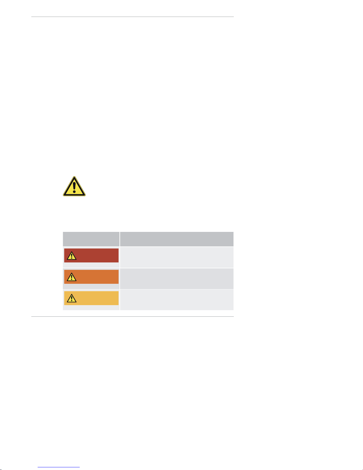
Danger symbol/
signal word
Meaning
DANGER
This signal word is used to indicate imminently
dangerous situations which, if not avoided, will
lead to serious injury or death.
WARNING
This signal word is used to indicate potentially
dangerous situations which, if not avoided, may
lead to serious injury or death.
CAUTION
This signal word is used to indicate potentially
dangerous situations which, if not avoided, may
lead to minor or moderate injury.
2-4L41C, 2-4M41, 2-4M41Z, 4L42C, 4M42 Safety
HATZ
Operator's Manual 9
Page 10
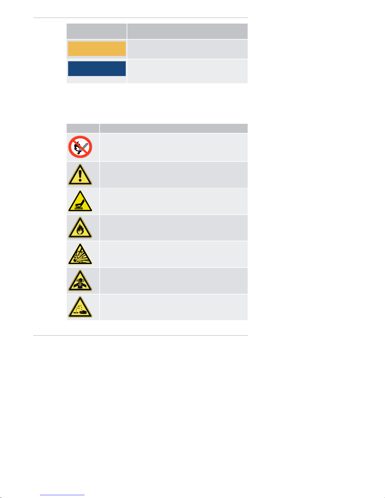
Danger symbol/
signal word
Meaning
CAUTION
This signal word, without a danger symbol, is
used to indicate the risk of property damage.
NOTICE
This signal word indicates additional useful information, such as operating tips and cross references.
3.1.4 Meaning of safety symbols
Explanation of symbols
The following table describes the meanings of the safety symbols used in
this Operator's Manual.
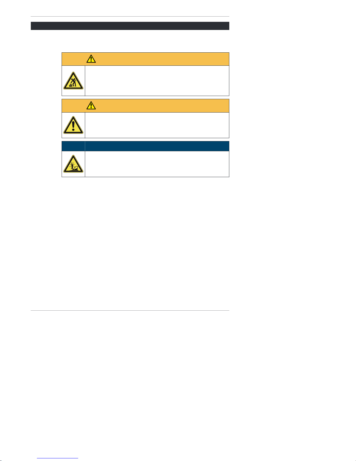
Symbol Meani ng
Smoking, fire and open flames are prohibited.
Warning of personal injury!
Warning of hot surfaces!
Warning of flammable substances!
Warning of explosive substances!
Warning of toxic engine exhaust!
Warning of corrosive substances!
Safety 2-4L41C, 2-4M41, 2-4M41Z, 4L42C, 4M42
10 Operator's Manual
HATZ
Page 11
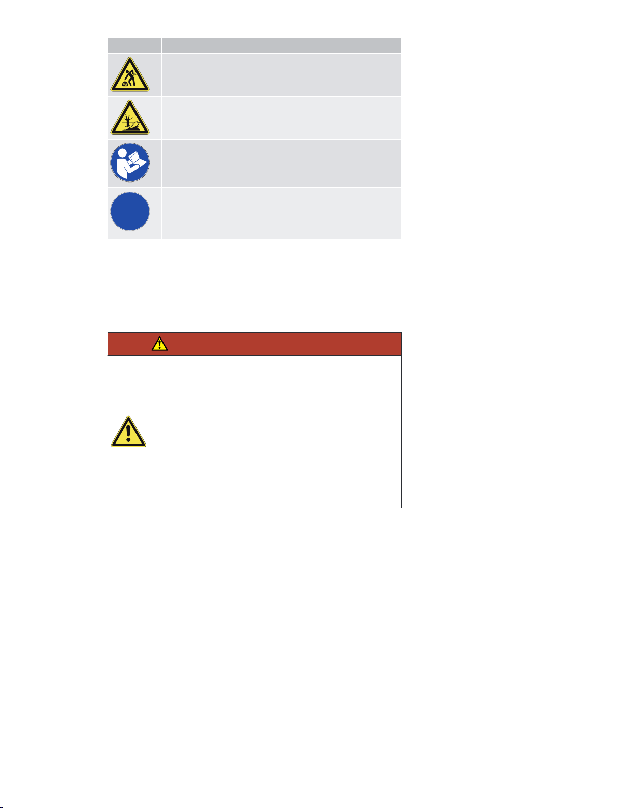
Symbol Meani ng
Warning of heavy loads!
Warning of environmental damage!
Comply with the Operator's Manual or additional documentation from other manufacturers or the user.
i
Additional information that is useful to the reader.
3.2 Safety notes
3.2.1 Operational safety
Introduction
This chapter contains all of the important safety instructions for personal protection and for safe and reliable operation. Additional, task-related safety instructions can be found at the beginning of each chapter.
DANGER
Danger to life, danger of injury, or danger of property damage due to failure to comply with the Operator's Manual and
the safety instructions contained therein.
▪ As the user of the machine, you must ensure that all people
working on the machine are familiar with the contents of this
Operator's Manual.
▪ Before working on the machine, read this Operator's Manual
carefully, paying special attention to the safety notes.
▪ Fulfill all required safety conditions before working on the
machine.
▪ Follow all general safety instructions as well as the specific
task-related safety instructions contained in the individual
chapters.
2-4L41C, 2-4M41, 2-4M41Z, 4L42C, 4M42 Safety
HATZ
Operator's Manual 11
Page 12

Using the machine
▪ Only operate the machine for the purposes described in the chapter 3.1.1
Intended use and foreseeable misuse, page 7.
Compliance with other regulations
▪ Adhere to the applicable accident prevention regulations of the trade asso-
ciations.
▪ Comply with the regulations concerning the minimum safety and health re-
quirements for the use of work equipment by workers at work.
▪ In addition, local safety, accident prevention and environmental regula-
tions also apply when operating the machine.
Operating personnel
▪ The machine may only be operated by qualified personnel. The personnel
must have read and understood this Operator's Manual or must be able to
demonstrate the necessary qualifications for working with this equipment,
acquired in training/instructional courses.
▪ The operating personnel must not be under the influence of drugs, medi-
cation or alcohol.
Personal protective equipment
During operation and maintenance of the machine, personal protective
equipment must be available and must be used if necessary. The required
personal protective equipment is specified in the description of the operating
steps.
Personal protective
equipment
Pictogram Function
Safety shoes Safety shoes offer protection
against:
▪ Slipping
▪ Falling objects
Hearing protection Hearing protection offers protec-
tion against ear injuries due to
excessive and constant noise.
Safety gloves Safety gloves protect the hands
against injury, e.g. from battery
acid.
Safety 2-4L41C, 2-4M41, 2-4M41Z, 4L42C, 4M42
12 Operator's Manual
HATZ
Page 13
Personal protective
equipment
Pictogram Function
Safety goggles
(with side protection)
Safety goggles protect the eyes
from flying objects (e.g. dust
particles, spraying liquids,
spraying acid).
Working clothes Wear close-fitting clothing. How-
ever, it must not restrict the
wearer's freedom of movement.
Warning labels and information signs on the machine
The warning and notice labels on the machine must be followed (see the
chapter 3.3 Labels, page 19).
The warning and notice labels must be kept legible and must be replaced if
necessary. For this purpose, contact your nearest HATZ service s tati on.
Maintenance work
Maintenance work that goes beyond the scope described in this manual
must only be performed by qualified technicians (see the chapter 2 General
information, page 6).
Independent maintenance work and constructional changes to the machine,
especially to the safety equipment, are not permitted.
Safety equipment
Safety equipment must not be modified and must not be rendered ineffective
during normal operation.
General safety instructions
DANGER
Danger to life and danger of injury due to failure to follow
the warnings on the machine and in the Operator's Manual.
▪ Heed the warnings on the machine and in the Operator's
Manual.
2-4L41C, 2-4M41, 2-4M41Z, 4L42C, 4M42 Safety
HATZ
Operator's Manual 13
Page 14
WARNING
Danger of injury and danger of incorrect operation due to
inadequate personnel qualifications.
▪ The personnel must have read and understood this Opera-
tor's Manual or must be able to demonstrate the necessary
qualifications for working with this equipment, acquired in
training/instructional courses.
▪ Only qualified personnel is permitted to operate and main-
tain this machine.
▪ Failure to comply will cause the warranty to be void.
WARNING
Danger of injury from the failure to follow the operating instructions and from performing unauthorized tasks on the
machine.
▪ Follow all instructions.
▪ Do not perform activities that are not authorized. Contact
properly trained personnel if necessary.
CAUTION
Danger of injury from overloading the body.
Lifting the machine to transport it or to move it to another location can lead to injuries (of the back, for example).
▪ Only lift the machine with a hoist (see the chapter 6.1 Trans-
port, page 31).
3.2.2 Machine-specific safety i nstructions for operation
Introduction
The machine can pose residual risks during operation. To eliminate these
risks, all persons working on the machine must follow the general and machine-specific safety instructions.
If you have an engine that is not yet installed in a machine, it is imperative
that you follow the Assembly Ins truction s fo r HATZ Diesel Engines before installing the engine.
These assembly instructions contain important information on safe installation.
If the engine is installed in a machine or assembled with other machines to
form a machine, it is prohibited to start the engine before it has been determined that the newly created machine fulfills all safety-related requirements
and applicable legal regulations.
Safety 2-4L41C, 2-4M41, 2-4M41Z, 4L42C, 4M42
14 Operator's Manual
HATZ
Page 15
Safe operat ion
▪ Before switching on the machine, ensure that no one can be injured when
the machine is started up.
▪ During machine operation, ensure that unauthorized persons do not have
access to the area in which the machine has an impact.
▪ Parts of the exhaust gas system and the surface of the engine become hot
during operation. Risk of injury from touching hot parts! Let the engine cool
before maintenance.
▪ Do not refuel during operation.
Faults
▪ Immediately eliminate faults that compromise safety.
▪ Switch off the machine and do not take into service again until all faults
have been eliminated.
Safety instructions for operation
DANGER
Danger to life from inhaling exhaust gases.
Toxic engine exhaust gases can lead to loss of consciousness
and even death in closed-off and poorly ventilated rooms.
▪ Never operate the machine in closed-off or poorly ventilated
rooms.
▪ Do not breathe in the exhaust gases.
DANGER
Fire hazard from fuel.
Leaked or spilled fuel can ignite on hot engine parts and cause
serious burn injuries.
▪ Only refuel when the engine is switched off.
▪ Never refuel in the vicinity of open flames or sparks that can
cause ignition.
▪ Do not smoke.
▪ Do not spill fuel.
2-4L41C, 2-4M41, 2-4M41Z, 4L42C, 4M42 Safety
HATZ
Operator's Manual 15
Page 16

CAUTION
Danger of injury from defective crankhandle.
A damaged or broken handle bar can cause injuries. A worn
cranking shaft can slip out of the starting mechanism when starting and also cause injuries.
▪ Check the crankhandle for a broken handle bar, worn crank-
ing shaft, etc.; replace if necessary.
3.2.3 Machine-specific safety instructions for maintenance work
Introduction
The machine can pose residual risks during maintenance. To eliminate
these risks, all persons working on the machine must follow the general and
machine-specific safety instructions.
Maintenance intervals
▪ Strictly adhere to the maintenance intervals.
▪ Check the safety equipment regularly to ensure it is in good condition and
functioning properly.
▪ Check connections, cables and fasteners regularly to ensure they are in
good condition.
Maintenance work
Maintenance work that goes beyond the scope described in this manual
must only be performed by qualified technicians. We recommend that you
work with one of the more than 500 HATZ service s tation s.
Replacing parts
▪ When replacing defective components, we recommend that you use gen-
uine HA TZ origi nal spar e parts (see the chapter 2 General information,
page 6).
▪ When disposing of parts that can no longer be used, do so in accordance
with local environmental regulations or send them to a recycling center.
Measures following maintenance and troubleshooting
▪ Securely reconnect loose electrical connections; check that the electrical
components and equipment are functioning properly.
▪ Check the entire machine for foreign bodies; remove any foreign bodies.
Safety 2-4L41C, 2-4M41, 2-4M41Z, 4L42C, 4M42
16 Operator's Manual
HATZ
Page 17

Safety instructions for maintenance work
DANGER
Danger of explosion from flammable cleaning agents.
Cleaning with benzene is an explosion hazard. It is highly flammable, can become electrostatically charged and can generate
an explosive gas-air mixture.
▪ Use halogen-free, cold cleaners with a high flashpoint for
cleaning.
WARNING
Danger of injury from compressed air and dust particles.
Eye injuries may occur when cleaning with compressed air.
▪ Wear safety goggles.
CAUTION
Danger of injury if maintenance instructions are not followed.
▪ Only perform maintenance when the engine is switched off.
▪ For engines with an electric starter:
Disconnect the negative battery terminal.
Protect the starting key against unauthorized access.
CAUTION
Danger of burns.
There is a danger of burns when working on a hot engine.
▪ Let the engine cool before maintenance.
2-4L41C, 2-4M41, 2-4M41Z, 4L42C, 4M42 Safety
HATZ
Operator's Manual 17
Page 18
3.2.4 Electrical equipment
Safety notes
DANGER
Danger to life, danger of injury or danger of property damage due to incorrect use of batteries.
▪ Do not place tools on the battery.
▪ Before performing work on the electrical equipment, always
disconnect the negative terminal of the battery.
▪ Never swap the positive (+) and negative (–) battery termi-
nals.
▪ When installing the battery, first connect the positiv e cable
and then the negat ive c able.
▪ When removing the battery, first disconnect the n egative
cable and then the pos itive cable.
▪ It is imperative that you prevent short circuits and mass con-
tact of current-carrying cables.
▪ If faults occur, check the cable connections for good con-
tact.
DANGER
Danger of explosion from flammable substances.
There is a danger of explosion from flammable gases.
▪ Keep batteries away from open flames and incendiary
sparks.
▪ Do not smoke when working with batteries.
CAUTION
Danger of chemical burns
Chemical burns can occur when using batteries for the electrical
operation.
▪ Protect your eyes, skin, and clothing from corrosive battery
acid.
▪ Immediately rinse areas affected by splashed acid with clear
water and consult a physician if necessary.
Safety 2-4L41C, 2-4M41, 2-4M41Z, 4L42C, 4M42
18 Operator's Manual
HATZ
Page 19
NOTICE
▪ The necessary wiring diagrams are included with the ma-
chine if it is equipped with electrical equipment. Additional
wiring diagrams can be requested when needed.
▪ We cannot be held liable for electrical equipment that is not
designed according to HATZ wiring diagrams.
▪ Promptly replace faulty indicator lamps.
▪ Do not pull out the starting key during operation.
▪ Do not disconnect the battery while the machine is running. Resulting volt-
age peaks could destroy the electronic components.
▪ When performing a manual emergency start, leave the (possibly depleted)
battery connected.
▪ When cleaning, do no spray the electrical equipment components with a
water jet or high pressure cleaner.
▪ When performing welding work on the machine, disconnect the battery
and place the ground clamp of the welding equipment as close as possible
to the welding area. Disconnect the plug-in connection to the voltage regulator.
3.3 Labels
Overvi ew
The following labels are found on the machine:
▪ Engine type plate
▪ Warning labels and information signs on the engine
▪ Warning labels and information signs on the crankhandle
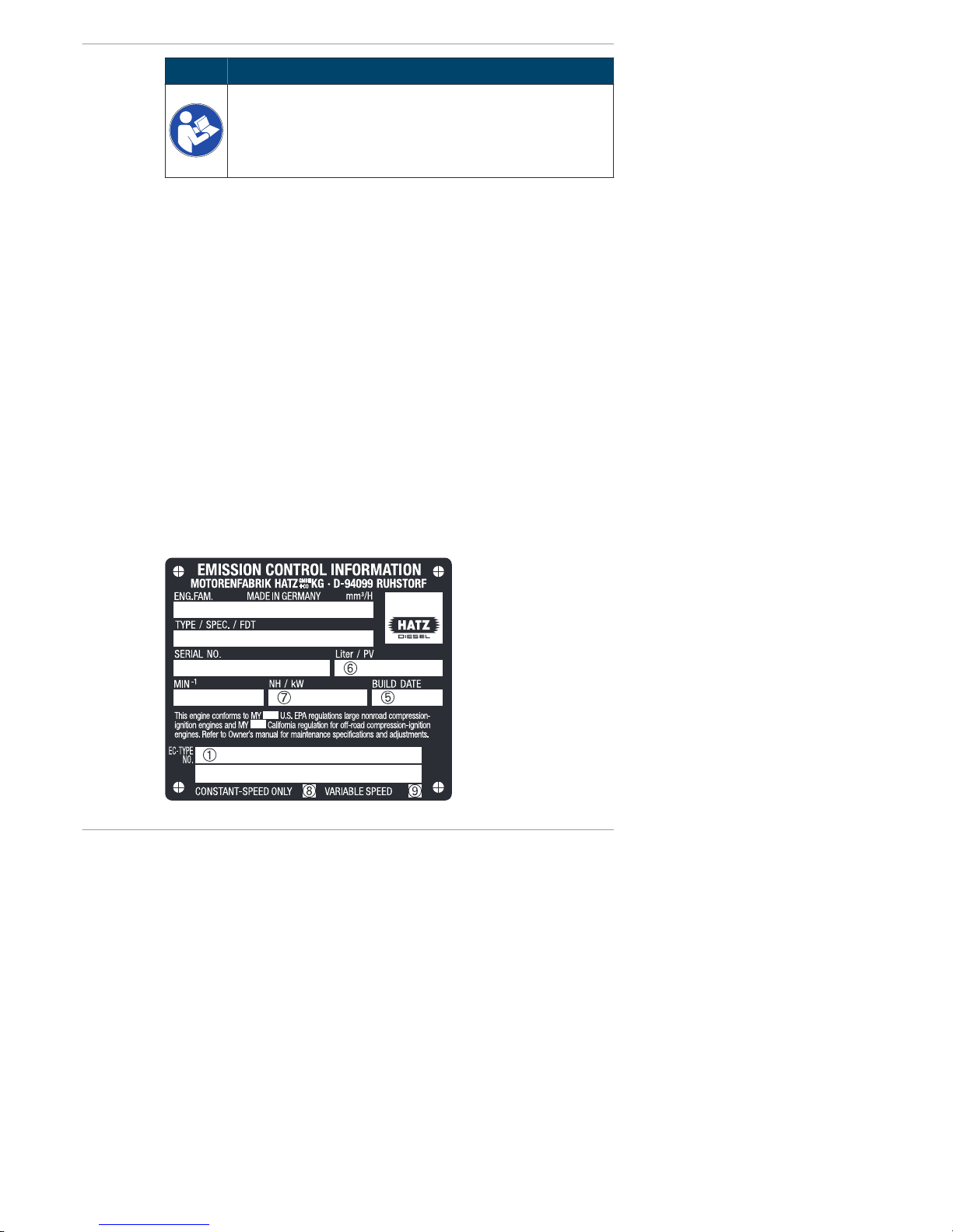
Engine type plate
➀
➁
➂
➃
2-4L41C, 2-4M41, 2-4M41Z, 4L42C, 4M42 Safety
HATZ
Operator's Manual 19
Page 20
The engine type plate is located on the crankcase or sound protection hood
and contains the following engine information:
1 Number of the engine family or the EU approval (for engines with ex-
haust certificate only)
2 Engine type, customer specification and setting of pumping start (°
crankshaft before top dead center)
3 Engine serial number
4 Max. engine speed (rpm)
5 Model year
6 Displacement (liters) and inspection requirement for special settings
7 Injection pump effective stroke (mm) and engine capacity (kW)
8 “Constant speed only” (for engines with EPA/CARB exhaust certificate
only)
9 “Variable speed” (for engines with EPA/CARB exhaust certificate only)
The following data must always be specified for requests and spare part orders
2 Engine type and customer specification
3 Engine serial number
4 Max. engine speed (rpm)
Warning labels and information signs on the engine
Label Meani ng
max
OIL
Maintenance instructions (see the
chapter 8.1 General maintenance instructions, page 55)
Safety 2-4L41C, 2-4M41, 2-4M41Z, 4L42C, 4M42
20 Operator's Manual
HATZ
Page 21
Label Meani ng
0000 036 144
CAUTION!
Damage from inadequate engine
cooling.
▪ Only run the engine when all cov-
ers are installed.
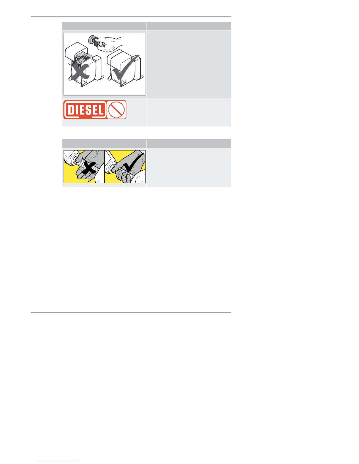
BIO
DIESEL
052 356 02
Refuel with diesel fuel only. Specification, see the chapter 4.2 Fuel,
page 23
Do not use bio diesel.
Warning labels and information signs on the crankhandle
Label Meani ng
0000 038 928 01
Hold the handle bar so that it cannot
twist, and quickly turn the crank so
that continuous traction between the
engine and crank is ensured, see
the chapter 7.5.1 Starting the engine
with crankhandle, page 38.
2-4L41C, 2-4M41, 2-4M41Z, 4L42C, 4M42 Safety
HATZ
Operator's Manual 21
Page 22

4 Technical data
4.1 Engine
Type 2L41C
2M41.
3L41C
3M41.
4L41C /
4L42C
4M41. / 4M42
Type
Air-cooled four stroke diesel engine
Combustion system
Direct injection
Number of cylinders
2 3 4
Bore/stroke mm 102 / 105 102 / 105 102 / 105
Displacement cm
3
1716 2574 3432
Engine oil pressure at oil
temperature of 100 ±
20 °C
Min. 0.6 bar at 850 rpm
Engine oil consumption
(after running-in period)
Max. 1% of fuel consumption, pertaining to full load
Sense of rotation
When viewing flywheel: left
Tappet clearance at 10–
30 °C
inlet/outlet
mm 0.10
Net weight
.M41
.M41Z
4M42
.L41C
4L42C
Approx.
kg
258
263
303
308
315
363
373
388
378
433
438
Max. perm. inclination
during continuous operation in direction
With /
without
oil sump
With
oil sump
Without
oil sump
Only with
oil sump
Operating side
Exhaust air side
Timing cover side
Flywheel side
30°
1)
30°
1)
30°
1)
30°
1)
30°
1)
30°
1)
25°
1)
22°
1)
25°
1)
30°
1)
25°
1)
25°
1)
25°
1)
30°
1)
15°
1)
18°
1)
Battery capacity Min/max 12 V – 88/143 Ah/24 V – 55/110 Ah
1)
Exceeding these limit values causes engine damage.
Technical data 2-4L41C, 2-4M41, 2-4M41Z, 4L42C, 4M42
22 Operator's Manual
HATZ
Page 23

Engine oil capacities and dipstick equipment
Typ e Oil su mp Engine oil capacity
2)
liters
Mark on the dip-
stick
2L41C
2M41Z
With
Without
7.5
4.5
C
A
2M41 With
Without
8.5
5.5
C
A
3L41C
3M41Z
With
Without
10.5
8.0
D
A
3M41 With
Without
11.0
8.5
D
A
4L41C
4L42C
4M41Z
With
Without
13.0
–
D
–
4M41
4M42
With
Without
14.0
–
D
–
2)
These values are approximations only. The max. mark on the dipstick is
decisive in any case (see the chapter 7.9 Checking the oil level and adding
oil if necessary, page 53).
4.2 Fuel
Fuel typ e
All types of diesel fuel that meet the minimum requirements of the following
specifications are suitable:
▪ EN 590 or
▪ BS 2869 A1 / A2 or
▪ ASTM D 975- 1D / 2D
CAUTION
Danger of engine damage from low quality fuel.
The use of fuel that does not meet the specifications can lead to
engine damage.
▪ The use of fuel that does not meet specifications requires
approval by Motorenfabrik HATZ (main plant).
Winter fuel
When outside temperatures drop below 0 °C, use winter fuel or mix in petroleum in advance:
2-4L41C, 2-4M41, 2-4M41Z, 4L42C, 4M42 Technical data
HATZ
Operator's Manual 23
Page 24
Lowest ambi ent temperature at start [°C]
Percentage of petroleum [%] for
Summer f uel Winter fuel
0 to -10
-10 to -15
-15 to -20
-20 to -30
20
30
50
‑
‑
‑
20
50
4.3 Engine oil
Oil quality
All oil brands that meet at least one of the following specifications are suitable:
▪ ACEA – B2 / E2 or better
▪ API – CD / CE / CF / CF-4 / CG-4 or better
If engine oils of a low quality standard are used, the oil change interval must
be reduced from 250 to 150 or from 500 to 250 operating hours depending
on the engine specification.
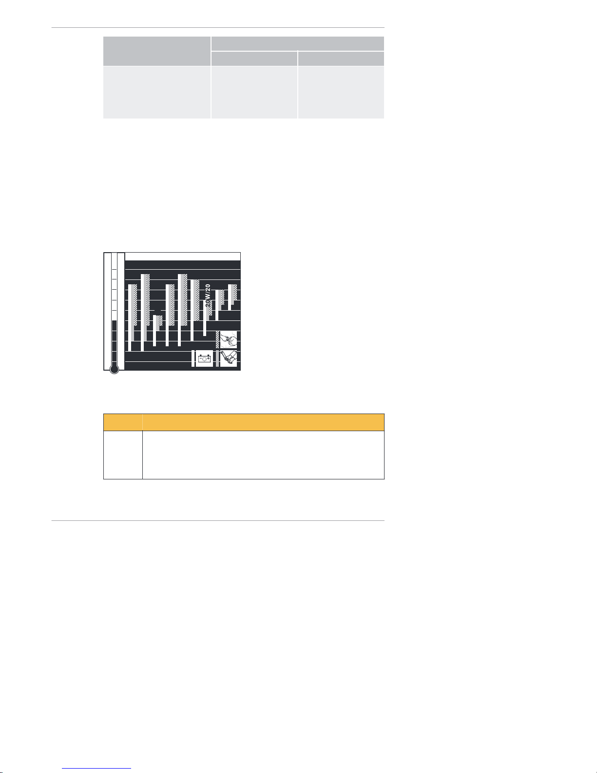
Oil viscosity
-40
-30
-20
-10
0
10
20
30
4050104
86
68
50
32
14
-4
-22
-40
OIL: S AE...
°C°F
5W/30
5W/40
10W
/4
0
10W
/30
15W
/4
0
30
4
0
122
10 W
Choose the recommended viscosity based on the type of start (recoil, crank
handle or electric) and on the engine temperature at which the engine will be
operated.
CAUTION
Engine damage from unsuitable engine oil.
Unsuitable engine oil considerably reduces engine service life.
Only use engine oil that fulfills the specifications stipulated
above.
Technical data 2-4L41C, 2-4M41, 2-4M41Z, 4L42C, 4M42
24 Operator's Manual
HATZ
Page 25
5 Engine design
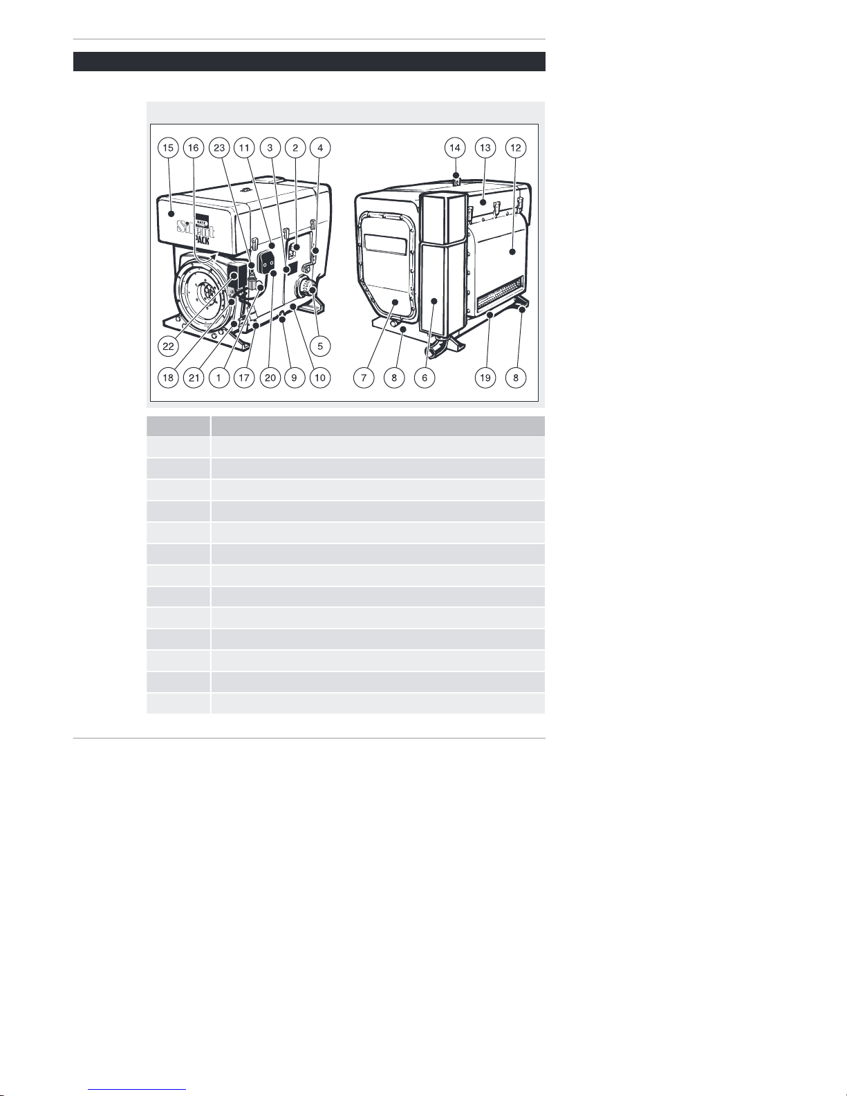
Engine 2-4L 41C
Encapsulated model "Silent Pack"
Pos. Desig nati on
1 Access cap for fuel feed pump
2 Oil filling opening and dipstick
3 Type plate
4 Speed control lever
5 Oil filter
6 Exhaust silencer (encapsulated)
7 Cover for air guide housing (access to cooling fan belt)
8 Engine brackets
9 Oil drain screw
10 Cover plate on operating side
11 Side wall
12 Exhaust air duct
13 Capsule hood
2-4L41C, 2-4M41, 2-4M41Z, 4L42C, 4M42 Engine design
HATZ
Operator's Manual 25
Page 26
Pos. Desig nati on
14 Retractable lifting eye, max. load 5000 N
15 Capsule intake shaft
16 Intake opening for combustion air
17 Fuel feed line with fuel prefilter
18 Fuel return line
19 Cover plate on exhaust side
20 Central connector for electrical equipment
21 Battery connections
22 Powerbox
23 Electrical maintenance switch for air filter
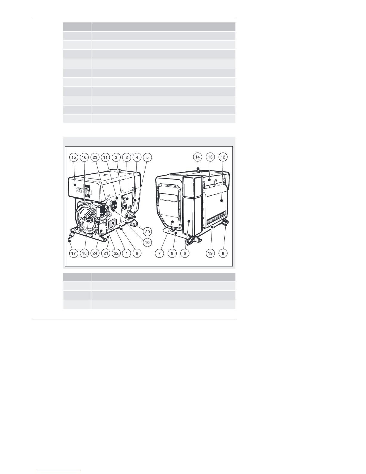
Engin e 4L42C
Encapsulated model "Silent Pack"
Pos. Desig nati on
1 Electronic control unit
2 Oil filling opening and dipstick
3 Type plate
Engine design 2-4L41C, 2-4M41, 2-4M41Z, 4L42C, 4M42
26 Operator's Manual
HATZ
Page 27

Pos. Desig nati on
4 Speed control lever
5 Oil filter
6 Exhaust silencer (encapsulated)
7 Cover for air guide housing (access to cooling fan belt)
8 Engine brackets
9 Oil drain screw
10 Cover plate on operating side
11 Side wall
12 Exhaust air duct
13 Capsule hood
14 Retractable lifting eye, max. load 5000 N
15 Capsule intake shaft
16 Intake opening for combustion air
17 Fuel feed line with fuel prefilter and manual fuel pump
18 Fuel return line
19 Cover plate on exhaust side
20 Central connector for electrical equipment
21 Battery connections
22 Powerbox
23 Electrical maintenance switch for air filter
24 Fuel filter
2-4L41C, 2-4M41, 2-4M41Z, 4L42C, 4M42 Engine design
HATZ
Operator's Manual 27
Page 28
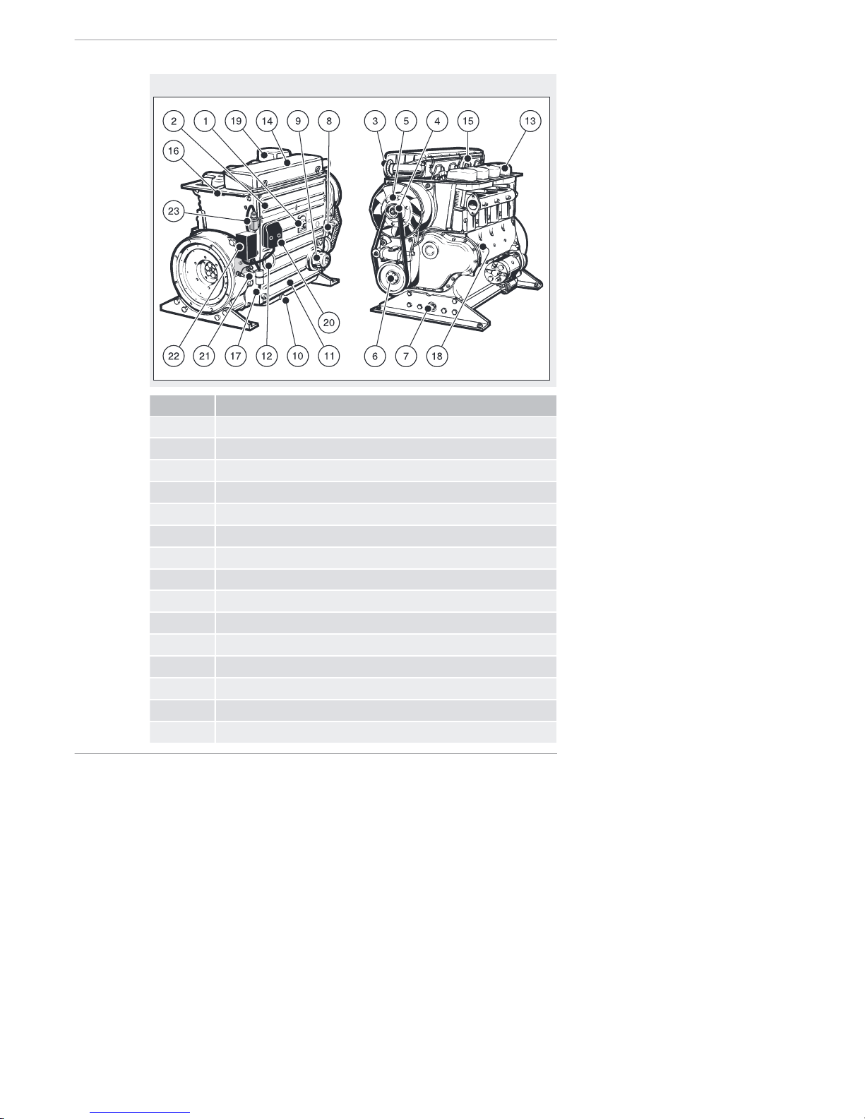
Engine 2-4M41, 2-4M41Z
Standard model
Pos. Desig nati on
1 Oil filling opening and dipstick
2 Side trim panel
3 Intake opening for combustion air
4 Cooling fan belt
5 Cooling fan with installed three phase alternator
6 1/2-inch square socket for turning the engine
7 Oil drain screw
8 Speed control lever
9 Oil filter
10 Oil drain screw (on oil sump)
11 Cooling air guide for oil cooler
12 Access cap for fuel feed pump
13 Cylinder head cover
14 Air filter housing cover
15 Lifting eye, max. load 5000 N
Engine design 2-4L41C, 2-4M41, 2-4M41Z, 4L42C, 4M42
28 Operator's Manual
HATZ
Page 29
Pos. Desig nati on
16 Fuel return line
17 Fuel feed line with fuel prefilter
18 Type plate
19 Silencer
20 Central connector for electrical equipment
21 Battery connections
22 Powerbox
23 Electrical maintenance switch for air filter
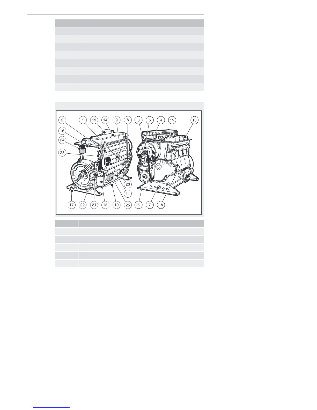
Engine 4M42
Standard model
Pos. Desig nati on
1 Oil filling opening and dipstick
2 Side trim panel
3 Intake opening for combustion air
4 Cooling fan belt
5 Cooling fan with installed three phase alternator
2-4L41C, 2-4M41, 2-4M41Z, 4L42C, 4M42 Engine design
HATZ
Operator's Manual 29
Page 30

Pos. Desig nati on
6 1/2-inch square socket for turning the engine
7 Oil drain screw
8 Speed control lever
9 Oil filter
10 Oil drain screw (on oil sump)
11 Cooling air guide for oil cooler
12 Fuel filter
13 Cylinder head cover
14 Air filter housing cover
15 Lifting eye, max. load 5000 N
16 Fuel return line
17 Fuel feed line with fuel prefilter and manual fuel pump
18 Type plate
19 Silencer
20 Central connector for electrical equipment
21 Battery connections
22 Powerbox
23 Electrical maintenance switch for air filter
24 Exhaust gas return valve (EGR)
25 Electronic control unit
Engine design 2-4L41C, 2-4M41, 2-4M41Z, 4L42C, 4M42
30 Operator's Manual
HATZ
Page 31
6 Transport, assembly and commissioning
6.1 Transport
Safety notes
CAUTION
Danger of injury from overloading the body.
Lifting the machine to transport it or to move it to another location can lead to injuries (of the back, for example).
▪ Only lift the machine with a hoist.
CAUTION
Only use lifting lugs for transporting the engine.
Do not use for lifting the entire machine.
NOTICE
Danger of environmental damage from leaking fluid.
If the machine is tilted, engine oil and diesel fuel can run out.
▪ Only transport the machine in an upright position.
Transport conditions
▪ Only lift the engine by the standard fitted lifting lugs.
▪ When transporting the machine, follow the safety instructions.
▪ When transporting, follow the applicable safety and accident prevention
regulations of the trade associations.
▪ After delivery, check the machine for completeness and transport damage.
▪ Only transport the machine when it is switched off and has cooled down.
▪ If you have questions on transporting the machine, please contact your
nearest HATZ ser vic e station. For contact data, see the chapter 1 "Notices", page 5 or www.hatz-diesel.c om.
6.2 Assembly instructions
Assembly notes
HATZ diesel engines are efficient, robust and long-lived. Therefore, they are
usually installed in machines that are used for commercial purposes.
The machine manufacturer must follow the applicable regulations regarding
machine safety – the engine is a part of a machine.
2-4L41C, 2-4M41, 2-4M41Z, 4L42C, 4M42 Transport, assembly and commissioning
HATZ
Operator's Manual 31
Page 32

Depending on the use and installation of the engine, it may be necessary for
the machine manufacturer and machine user to install safety equipment to
prevent inappropriate use. Note the following:
▪ Parts of the exhaust gas system and the engine surface become hot dur-
ing operation and should not be touched until they cool down after the engine is switched off.
▪ Incorrect cable connections and incorrect operation of the electrical equip-
ment can lead to sparking and must be avoided.
▪ After the engine is installed in the machine, rotating parts must be protect-
ed against contact.
HATZ safety equipment is available for the belt drive of the cooling fan and
alternator.
▪ Comply with all notice and warning labels on the engine and keep them in
a legible condition. If a label should become detached or be difficult to
read, it must be replaced promptly. For this purpose, contact your nearest
HATZ service station.
▪ Any improper modification of the engine results in a loss of liability cover-
age for resulting damage.
Only regular maintenance, as specified in this Operator's Manual, will maintain the operating readiness of the engine.
The assembly instructions contain important information on how to safely assemble the engine. They are available from any Hatz serv ice station .
If you have any questions, please contact your nearest HATZ serv ice station before commissioning the engine.
6.3 Preparations for commissioning
▪ Check the delivered parts for completeness, damage and other noticeable
issues.
▪ Ensure that the setup location is adequately ventilated.
DANGER
Danger to life from inhaling exhaust gases.
Toxic engine exhaust gases can lead to loss of consciousness
and even death in closed-off and poorly ventilated rooms.
▪ Never operate the machine in closed-off or poorly ventilated
rooms.
▪ Do not breathe in the exhaust gases.
Transport, assembly and commissioning 2-4L41C, 2-4M41, 2-4M41Z, 4L42C, 4M42
32 Operator's Manual
HATZ
Page 33

7 Operation and use
7.1 Safety notes
NOTICE
Comply with the safety chapter!
Follow the basic safety instructions in the chapter 3 Safety,
page 7.
WARNING
Danger of injury from damage and defects on the machine.
▪ Do not take the machine into service if damage has been lo-
calized and identified.
▪ Replace faulty components.
WARNING
Danger of injury from the failure to follow the operating instructions and from performing unauthorized tasks on the
machine.
▪ Define the responsibilities of the personnel taking the ma-
chine into service.
▪ Replace faulty machine parts immediately.
▪ Check the installation conditions when the machine is first
taken into service and after the machine has been inactive
for a lengthy period.
CAUTION
Danger of engine damage from low load operation.
Operating the engine at no load or at very low load for an extended period can impair the running characteristics of the engine.
▪ Make sure that the engine load is at least 15 %.
▪ Before switching off the engine following low load operation,
briefly operate it at a considerably higher load.
7.2 Performing tests
Before starting
Before starting the engine, several tests need to be performed to ensure the
machine is working properly.
2-4L41C, 2-4M41, 2-4M41Z, 4L42C, 4M42 Operation and use
HATZ
Operator's Manual 33
Page 34

Procedure
Step Test
1 The machine is standing securely and on a level surface.
2 The installation location is adequately ventilated.
3 There is a sufficient amount of fuel in the fuel tank (see the chap-
ter 4.2 Fuel, page 23).
4 There is a sufficient amount of engine oil in the engine housing
(see the chapter 4.3 Engine oil, page 24).
5 For hand start:
▪ Crankhandle in functional condition.
▪ Sliding area between crankhandle and guide sleeve lightly
greased.
6 No persons are located in the danger zone of the engine or ma-
chine.
7 All safety equipment is in place.
7.3 Start preparation
Procedure
Step Activity
1 Before the first start and with an empty fuel system:
▪ Pump the fuel with the manual lever (see the chapter 7.3.1
Pumping fuel with the manual lever, page 34)
or
▪ Pump the fuel with the manual fuel pump (see the chapter
7.3.2 Pumping fuel with the manual fuel pump, page 35)
7.3.1 Pumping fuel with the manual lever
Requiremen ts
Pre-pumping of fuel with the manual lever of the fuel feed pump is necessary
in the following situations:
▪ Engine shuts down due to empty fuel tank
▪ at first filling of the fuel tank
▪ after changing the fuel filter
Operation and use 2-4L41C, 2-4M41, 2-4M41Z, 4L42C, 4M42
34 Operator's Manual
HATZ
Page 35

Overvi ew
Pos. Designation
1 Manual lever (fuel feed pump)
2 Return line
Procedure
Step Activity
1 Fill with fuel if necessary.
2 Remove the access cap for the fuel feed pump.
3 Actuate the manual lever (1) on the fuel feed pump until the fuel
audibly flows back into the fuel tank through the return line (2).
4 Install the access cap again.
7.3.2 Pumping fuel with the manual fuel pump
Requiremen ts
Pre-pumping of fuel with the manual fuel pump is necessary in the following
situations:
▪ Engine shuts down due to empty fuel tank
▪ at first filling of the fuel tank
▪ after changing the fuel filter
2-4L41C, 2-4M41, 2-4M41Z, 4L42C, 4M42 Operation and use
HATZ
Operator's Manual 35
Page 36

Model with manual fuel pump
Only for 4L42C and 4M42
2
3
Pos. Designation
1 Bleed screw
2 Filter
3 Rubber ball
Procedure
Step Activity
1 If there is air in the fuel system:
Fill with fuel if necessary.
2 Place a suitable container under the filter (2) to collect emerging
fuel.
3 Open the bleed screw (1) by approx. one turn.
4 Squeeze and release the rubber ball (3) repeatedly until fuel
emerges from the bleed screw (1).
5 Close the bleed screw (1) and then activate the rubber ball tw o
more times.
Operation and use 2-4L41C, 2-4M41, 2-4M41Z, 4L42C, 4M42
36 Operator's Manual
HATZ
Page 37

7.4 Setting the speed control
Overview
½
Procedure
Step Activity
1 Depending on the situation, place the speed control lev-
er in either the "1/2" or "Start" position.
NOTICE
i
A lower speed setting will cause less exhaust smoke when starting.
7.5 Starting the engine
Starting options
The standard equipment of the engine is an electric start mechanism. A
hand starter can be installed as an option.
If possible, separate the engine from the machine being driven by uncoupling it. Always switch the machine into idle mode.
2-4L41C, 2-4M41, 2-4M41Z, 4L42C, 4M42 Operation and use
HATZ
Operator's Manual 37
Page 38

Safety notes
DANGER
Danger to life from inhaling exhaust gases.
Toxic engine exhaust gases can lead to loss of consciousness
and even death in closed-off and poorly ventilated rooms.
▪ Never operate the machine in closed-off or poorly ventilated
rooms.
▪ Do not breathe in the exhaust gases.
CAUTION
Danger of injury from defective crankhandle.
A damaged or broken handle bar can cause injuries. A worn
cranking shaft can slip out of the starting mechanism when starting and also cause injuries.
▪ Check the crankhandle for a broken handle bar, worn crank-
ing shaft, etc.; replace if necessary.
CAUTION
Danger of injury and danger of engine damage from the use
of starting fluid.
▪ Danger of injury during hand starting because the use of
starting fluid can result in uncontrolled ignitions.
▪ Engine damage from uncontrolled ignitions.
▪ Never use starting fluid.
7.5.1 Starting the engine with crankhandle
This chapter contains the following sections:
▪ Prep aration s for crank ing th e engine:
Adjust the continuous decompression.
▪ Cran k the engine:
Crank the engine without compression (approx. 10–20 crank turns).
This lowers the resistance to rotation.
▪ Prep aration s for start ing th e engine:
Adjust the automatic decompression.
▪ Star t the engine:
Cranking starts the cylinders one after the other and the decompression
is automatically canceled.
Operation and use 2-4L41C, 2-4M41, 2-4M41Z, 4L42C, 4M42
38 Operator's Manual
HATZ
Page 39
Turni ng over the engi ne:
Safety note
CAUTION
Danger of engine damage from decompression while the
engine is running.
▪ Do not operate the decompression lever while the engine is
running.
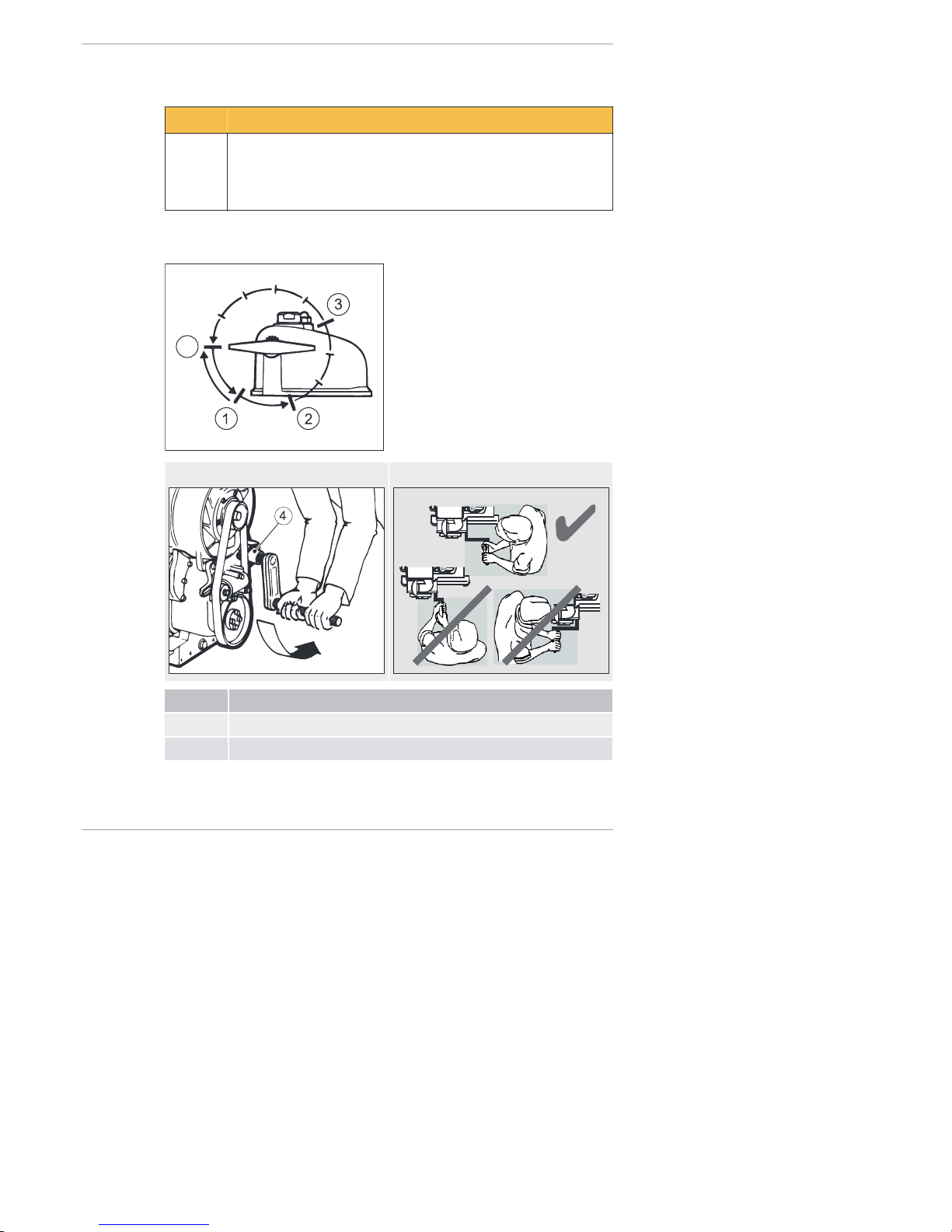
Overvi ew
Decompression lever
0
Attach the crankhandle Position of operator
Pos. Designation
0 - 3 Positions of the decompression lever
4 Guide sleeve
2-4L41C, 2-4M41, 2-4M41Z, 4L42C, 4M42 Operation and use
HATZ
Operator's Manual 39
Page 40

Preparat ion
Step Activity
1 Carry out start preparations (see the chapter 7.3 Start prepara-
tion, page 34).
2 Move the speed control lever into position "Start" (see the chap-
ter 7.4 Setting the speed control, page 37).
3 Move all decompression levers to position "1".
▪ 1 lever for two cylinder engine
▪ 3 levers for three cylinder engine
▪ 4 levers for four cylinder engine
NOTICE
i
Only operate the decompression lever while the engine is at a
standstill and observe the sense of rotation
▪ Only turn the decompression lever in the direction of the ar-
row.
▪ Exception: The lever can be turned directly back from posi-
tion "1" to "0".
▪ Position "1" is the continuous decompression setting.
Procedure
Step Activity
1 Insert the crankhandle into the guide sleeve (4).
2 Assume the correct position.
3 Grasp the handle bar with both hands.
4 Crank the engine until the crank resistance becomes markedly
less.
Operation and use 2-4L41C, 2-4M41, 2-4M41Z, 4L42C, 4M42
40 Operator's Manual
HATZ
Page 41
Starting the engine
Safety note
CAUTION
Danger of injury from recoiling of the engine.
▪ Use a crankhandle with a recoil damper.
▪ Hold the handle bar so that it cannot twist and quickly turn
the crank so that continuous traction between the engine
and crank is ensured.
▪ If recoil occurs due to cautious turning where the engine
starts in the opposite sense of rotation under certain circumstances (smoke from the air filter), release the crankhandle
immediately and stop the engine.
▪ To repeat the starting process, wait until the engine has
stopped; only then recommence start preparations.
CAUTION
Danger of injury if the crankhandle recoils or turns with the
engine.
▪ The use of crankhandles without recoil damping is not per-
missible within the European Union.
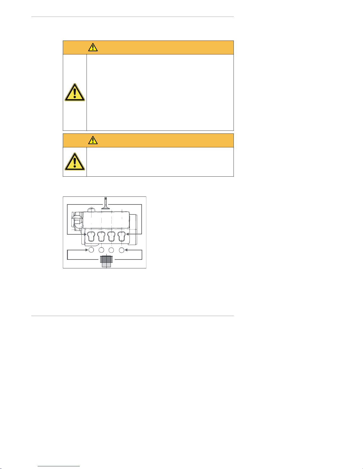
Overvi ew
Numbering of the valves and cylinders from the fan side
1
2
3
4
12 345678
2-4L41C, 2-4M41, 2-4M41Z, 4L42C, 4M42 Operation and use
HATZ
Operator's Manual 41
Page 42

Crankhandle Attach the crankhandle
Pos. Designation
1 Handle bar
2 Crank arm
3 Drive dog
4 Guide sleeve
Preparat ion
The decompression lever must be set depending on the number of cylinders
of the engines 2-4M41..
0
Operation and use 2-4L41C, 2-4M41, 2-4M41Z, 4L42C, 4M42
42 Operator's Manual
HATZ
Page 43

Step Activity
1 Setting the decompression lever:
▪ Two cylinder engine 2M41.
Turn the lever to position "2".
▪ Thr ee cyli nder engi ne 3M41.
Turn the levers of the 1st and 3rd cylinders to position "2".
Turn the lever of the 2nd cylinder to position "3".
▪ Four cylinder engine 4M41.
Turn the levers of the 1st, 3rd and 4th cylinders to position
"2".
Turn the lever of the 2nd cylinder to position "3".
Starting the engine with a recoil-dampened crankhandle
Step Activity
1 Assume the correct position.
2 Grasp the handle bar with both hands.
3 First turn the crankhandle slowly until the drive dog and the en-
gagement mechanism of the crankhandle engage.
4 Turn the crankhandle forcefully with increasing speed. When the
decompression lever engages in the "0" position (compression),
the highest possible speed must be reached.
5 As soon as the engine starts, pull the crankhandle out of the
guide sleeve.
NOTICE
i
If recoil occurs during the starting process, the crank arm/drive
dog linkage releases via the handle bar due to the short reverse
rotation.
Starting with a crankhandle without recoil damping
Only applies to engines 2-4M41.
Step Activity
1 Assume the correct position.
2 Grasp the handle bar (1) with both hands.
3 Slowly turn the crankhandle until the drive dog (3) engages.
2-4L41C, 2-4M41, 2-4M41Z, 4L42C, 4M42 Operation and use
HATZ
Operator's Manual 43
Page 44
Step Activity
4 Turn the crankhandle forcefully with increasing speed. When the
decompression lever engages in the "0" position (compression),
the highest possible speed must be reached.
5 As soon as the engine starts, pull the crankhandle out of the
guide sleeve (4).
7.5.2 Starting the engine with an electric starter
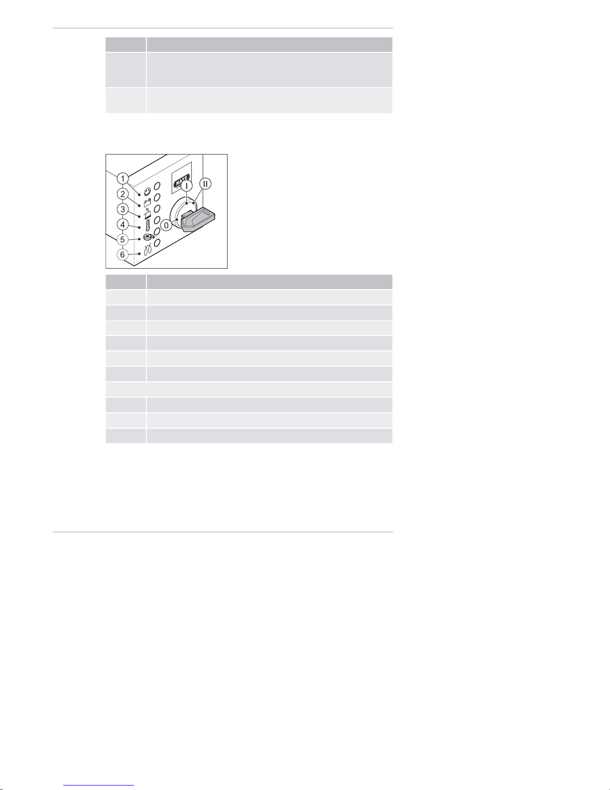
Standard model
Pos. Designation
1 Operating display
2 Charge control
3 Oil pressure display
4 Engine temperature display (option)
5 Air filter maintenance display
6 Pre glow display (option)
Ignition lock
0 Off
I Operation
II Starting
Operation and use 2-4L41C, 2-4M41, 2-4M41Z, 4L42C, 4M42
44 Operator's Manual
HATZ
Page 45

Procedure
NOTICE
i
▪ Start for max. 30 seconds. If the engine is still not running
after that, turn the starting key back to position "0" and eliminate the cause (see the chapter 9.1 Troubleshooting,
page 93).
▪ Turn the starting key to position "0" every time you want to
start the engine.
▪ The anti repeat device in the ignition lock makes it impossi-
ble for the starter to engage while the engine is running and
become damaged.
NOTICE
i
The starter protection module prevents the starter from engaging while the engine is running and becoming damaged.
▪ The starter protection module is required when the user
cannot detect at the ignition lock if the engine is still running
or is already at a standstill.
▪ In models equipped with a starter protection module, the
starting key must be kept in the 0 position for at least 8 seconds before another start is possible after the engine is
switched off.
Step Activity
1 Check the speed control (see the chapter 7.4 Setting the speed
control, page 37).
2 Insert the starting key all the way and turn to position "I".
Depending on the model, the following indicators light up:
▪ Charge control (2)
▪ Oil pressure display (3)
▪ Pre glow display (6) at temperatures below 0°C
NOTES:
▪ If the optional engine temperature display (4) lights up, the
cylinder head temperature is impermissibly high. Do not start
the engine; eliminate the cause.
▪ The air filter maintenance indicator (5) only lights up during
operation if the air filter needs to be cleaned or changed.
▪ When the optional pre glow display (6) goes out, continue with
step 3.
3 Turn the starting key to position "II".
2-4L41C, 2-4M41, 2-4M41Z, 4L42C, 4M42 Operation and use
HATZ
Operator's Manual 45
Page 46

Step Activity
4 As soon as the engine is running, release the starting key.
▪ The starting key springs back to position "I" and remains in
this position during operation.
▪ The charge control (2) and oil pressure display (3) go out.
▪ The operating display (1) lights up.
NOTICE
i
▪ In case of irregularities, switch off the engine immediately.
▪ Identify the fault and eliminate it.
▪ For details of troubleshooting, see the chapter 9.1 Trouble-
shooting, page 93.
Model with exhaust gas return valve
The engines 4L42C and 4M42 are equipped with an exhaust gas return
valve (EGR). The indicators change as follows:
Pos. Designation
5 Indicator EGR
Blink codes
The indicator (5) only flashes during operation if a problem arises in connection with the exhaust gas return system. This includes a dirty air filter. This
can be identified by the following flash code of the indicator (5):
▪ 7 times short flash (approx. 0.5 seconds) and 1 long flash (approx. 1.5
seconds).
▪ The flash code indicates that the air filter must be cleaned or changed
(see the chapter 8.2.11 Checking and cleaning the air filter cartridge,
page 76).
▪ If a different flash code appears, please contact the nearest Hat z servi ce.
Operation and use 2-4L41C, 2-4M41, 2-4M41Z, 4L42C, 4M42
46 Operator's Manual
HATZ
Page 47
NOTICE
i
If the electronics indicate a problem continuously for more than
15 minutes without interruption (flash code - display lamp (5)),
the engine switches off automatically.
▪ If the problem persists, the engine can be started but only
for another 15 minutes.
▪ If necessary, contact your nearest HATZ serv ice station .
Electrical automatic shutoff (additional equipment)
The identifying feature of the electrical automatic shutoff is brief flashing of
all indicators after the starting key is turned to position "I".
NOTICE
i
▪ If the engine stops again immediately after starting, or stops
independently during operation, this is an indication that a
monitoring element of the automatic shutoff has been activated.
▪ Remedy the fault before further starting attempts (see the
chapter 9.1 Troubleshooting, page 93).
▪ Despite the automatic shutoff, check the oil level every 8-15
operating hours (see the chapter 7.9 Checking the oil level
and adding oil if necessary, page 53).
▪ If the engine switches off due to an electrical fault signal or
due to insufficient oil pressure with the aid of the automatic
switch-off, an emergency start can be attempted by the
user. The user must bear responsibility for any resulting
damage (see the chapter 9.2 Emergency start, page 99).
7.6 Switching off the engine
Methods of switching off the engine
CAUTION
Danger of injury from unauthorized access.
There is a danger of injury if unauthorized persons handle the
machine.
▪ Protect the crankhandle and starting key against unauthor-
ized access upon breaks in operation or after completing
work.
2-4L41C, 2-4M41, 2-4M41Z, 4L42C, 4M42 Operation and use
HATZ
Operator's Manual 47
Page 48
CAUTION
Danger of engine damage.
▪ Never stop the engine on the decompression lever.
The engine can be switched off in different ways depending on how it is
equipped:
▪ Speed control lever (mechanical)
▪ Starting key (electrical)
7.6.1 Switching off the engine (mechanical)
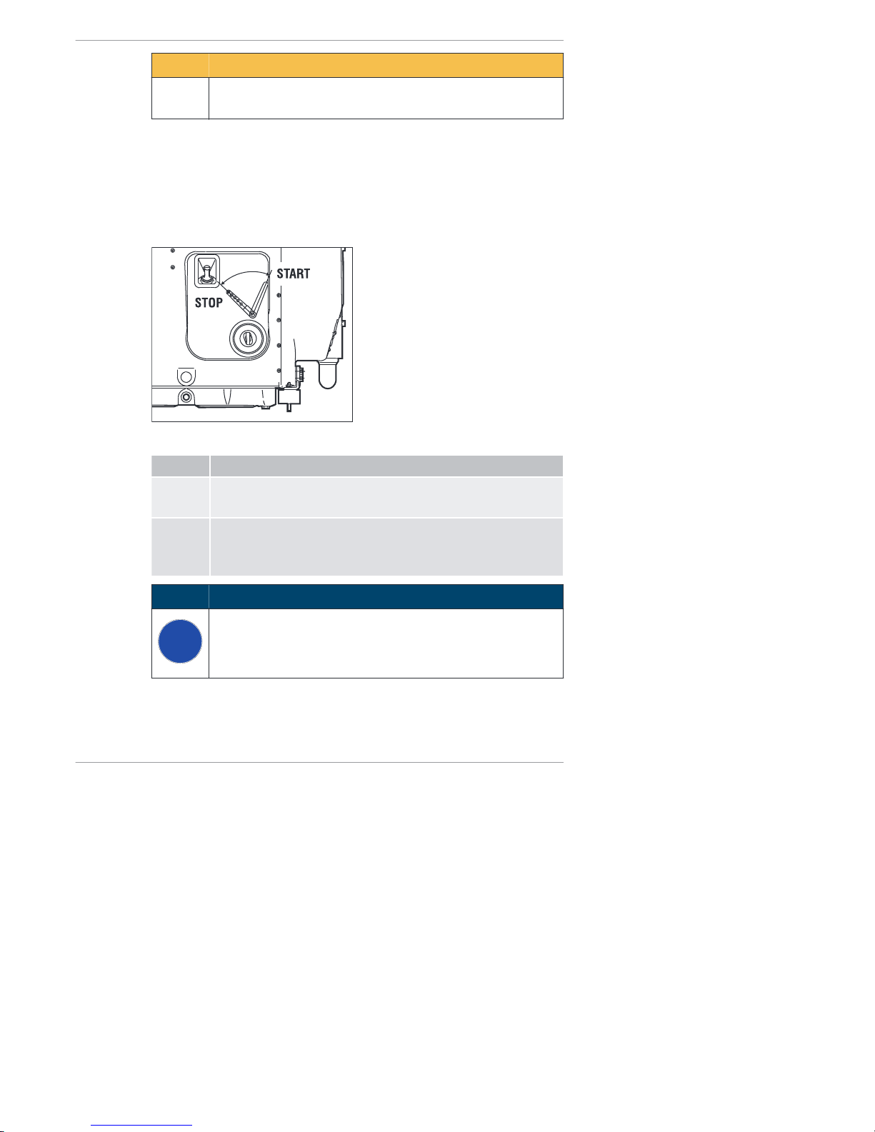
Overview
Procedure
Step Activity
1 Move the speed controller lever to the "STOP" position.
The engine switches off.
2 Additional step for engines with a starter:
▪ Turn the starting key to position "0".
All indicator lamps go out.
NOTICE
i
Engines with an automatic switch-off can also be switched off by
turning the starting key back to position "0".
Operation and use 2-4L41C, 2-4M41, 2-4M41Z, 4L42C, 4M42
48 Operator's Manual
HATZ
Page 49

7.6.2 Switching off the engine (electrical)
Overview
Pos. Designation
0 Off
I Operation
Procedure
NOTICE
i
Danger of full battery discharge.
▪ When the machine is switched off, always turn the starting
key to position "0" or else the battery may become fully discharged.
Step Activity
1 Turn the starting key to position "0".
The engine switches off.
All indicator lamps go out.
2 Remove the starting key.
Automatic electrical switch-off with fault storage
This is identified by brief flashing of all indicators after the starting key is
turned to position "I".
2-4L41C, 2-4M41, 2-4M41Z, 4L42C, 4M42 Operation and use
HATZ
Operator's Manual 49
Page 50

NOTICE
i
If the engine stops again immediately after starting, or stops independently during operation, this is an indication that a monitoring element of the automatic shutoff has been activated.
Procedure
Step Activity
1 Check the indicators (2-4).
After the engine comes to a standstill, the fault will continue to
be displayed by the indicator for approx. another 2 minutes.
2 Then the electrical equipment switches off automatically.
3 Set the starting key to position "0".
4 Turn the starting key back to position "I".
The fault display lights up again.
Remedy the fault before making further starting attempts (see
the chapter 9.1 Troubleshooting, page 93).
The indicator goes out at the next start.
7.7 Refueling
This diesel engine is intended for installation in a machine or for assembly
with other machines to form a machine and does not have its own fuel tank.
Follow the instructions from the manufacturer and comply with the following
safety information.
Safety notes
DANGER
Fire hazard from fuel.
Leaked or spilled fuel can ignite on hot engine parts and cause
serious burn injuries.
▪ Only refuel when the engine is switched off.
▪ Never refuel in the vicinity of open flames or sparks that can
cause ignition.
▪ Do not smoke.
▪ Do not spill fuel.
Operation and use 2-4L41C, 2-4M41, 2-4M41Z, 4L42C, 4M42
50 Operator's Manual
HATZ
Page 51

CAUTION
Danger of environmental damage from spilled fuel.
Do not overfill the fuel tank and do not spill fuel.
▪ Collect emerging fuel and dispose of it in an environmentally
compatible manner.
CAUTION
Engine damage from using low quality fuel.
The use of fuel that does not meet the specifications can lead to
engine damage.
▪ Only use the fuel specified in the chapter 4.2 Fuel, page 23.
▪ The use of fuel that does not meet specifications requires
approval by Motorenfabrik HATZ (main plant).
7.8 Checking the water separator
Only for engines 4L42C and 4M42
Safety notes
CAUTION
Danger of environmental damage from spilled fuel.
When water is drained from the water separator, a small amount
of fuel is drained as well.
▪ Catch the emerging water-fuel mixture and dispose of it in
an environmentally compatible manner.
NOTICE
i
The interval for checking the water separator depends entirely
on the proportion of water in the fuel and on the care exercised
during refueling; the water separator should be checked at least
once a week.
Overvi ew
Water in the fuel collects at the lowest point of the fuel filter in the water separator.
2-4L41C, 2-4M41, 2-4M41Z, 4L42C, 4M42 Operation and use
HATZ
Operator's Manual 51
Page 52

Pos. Desi gnat ion
1 Drain plug
2 Bleed screw
Procedure
Step Activity
1 Place a suitable container under the drain plug (1).
NOTE: In inaccessible locations, an extension hose can be
mounted on the drain screw (1).
2 Open the drain screw (1) and drain the water into the container.
3 If not enough liquid escapes, undo additional screw (2).
4 As soon as fuel escapes, close the drain plug (1) and screw (2).
NOTE: First water escapes then fuel. This can be seen by a
clear separator.
5 Dispose of the water-fuel mixture in an environmentally compati-
ble manner.
NOTICE
i
Note - If starting difficulties occur:
Bleed the injection system with the aid of the manual fuel pump
(see the chapter 7.3.2 Pumping fuel with the manual fuel pump,
page 35).
Operation and use 2-4L41C, 2-4M41, 2-4M41Z, 4L42C, 4M42
52 Operator's Manual
HATZ
Page 53

7.9 Checking the oil level and adding oil if necessary
Safety notes
CAUTION
Danger of burns.
There is a danger of burns when working on a hot engine.
▪ Wear safety gloves.
CAUTION
Danger of later engine damage.
▪ Operating the engine with an oil level below the min. mark
or above the max. mark can lead to engine damage.
▪ When checking the oil level, the machine must be horizontal
and the engine must have been switched off for a few minutes.
Overview — Checking oil level/adding oil
Pos. Designation
1 Dipstick
2 Code letter on the dipstick
2-4L41C, 2-4M41, 2-4M41Z, 4L42C, 4M42 Operation and use
HATZ
Operator's Manual 53
Page 54

Procedure — Checking oil level/adding oil
Step Activity
1 Switch off the engine and wait several minutes for the engine oil
to collect in the crank housing. The machine must be horizontal.
2 Remove contamination on the engine in the area of the dipstick
(1).
3 Pull out the dipstick and clean it.
4 Reinsert the dipstick.
5 Pull out the dipstick and check the oil level.
6 If the oil level is close to the min. mark, add engine oil to the
max. mark.
For specifications and viscosity see chapter 4.3 Engine oil,
page 24.
7 Reinsert the dipstick.
Operation and use 2-4L41C, 2-4M41, 2-4M41Z, 4L42C, 4M42
54 Operator's Manual
HATZ
Page 55

8 Maintenance
8.1 General maintenance instructions
Safety notes
WARNING
Danger of injury from the failure to follow the operating instructions and from performing unauthorized tasks on the
machine.
▪ Follow all instructions.
▪ Do not perform activities for which no qualification is availa-
ble. Contact properly trained personnel if necessary.
NOTICE
Comply with the safety chapter!
Follow the basic safety instructions in the chapter 3 Safety,
page 7.
▪ Maintenance tasks may only be performed by trained personnel.
▪ Accident prevention measures must be in accordance with the local acci-
dent prevention regulations.
▪ Perform setting and maintenance work at the specified intervals.
▪ Replace faulty machine parts as soon as possible.
▪ Always use personal protective equipment.
▪ Only use fully functional tools.
▪ Problems may occur if unsuitable spare parts are installed. We cannot ac-
cept responsibility for damage and secondary damage that result from
this. We therefore recommend the use of Hatz o rig inal spare p arts .
▪ Closely adhere to the maintenance conditions prescribed in this Operator's
Manual.
▪ Only make changes on the machine in agreement with the manufacturer.
▪ Only perform maintenance when the engine is switched off.
▪ Adhere to legal regulations when handling and disposing of used oil, fil-
ters, coolants, and cleaning agents.
▪ Protect the starting key against unauthorized access.
▪ Disconnect the negative battery terminal before carrying out maintenance
work.
▪ After completing maintenance work, check that all tools, bolts, aids and
other objects are removed from the machine and that all safety equipment
has been replaced.
2-4L41C, 2-4M41, 2-4M41Z, 4L42C, 4M42 Maintenance
HATZ
Operator's Manual 55
Page 56
▪ Before starting, ensure that no persons are located in the danger zone of
the engine or machine.
Performance of maintenance work
The entire machine is designed to be maintenance friendly. Parts that require maintenance are easily accessible.
▪ Perform maintenance work faithfully at the specified intervals to prevent
premature wear of the machine.
▪ Follow the notice and warning labels on the machine.
▪ Always retighten screw connections loosened during maintenance work.
▪ After the necessary maintenance and repair work is completed, perform a
function test (test run).
▪ For maintenance work that is not listed and described in the maintenance
documentation, please contact your nearest HATZ servic e stat ion .
8.2 Maintenance work
Safety note
CAUTION
Danger of injury if the maintenance instructions are not followed.
▪ Only perform maintenance while the engine is switched off.
▪ Protect the starting key against unauthorized access.
▪ For engines with a starter: disconnect the negative battery
terminal.
▪ After the maintenance work is completed, ensure that all
tools have been removed from the machine.
8.2.1 Maintenance notice label
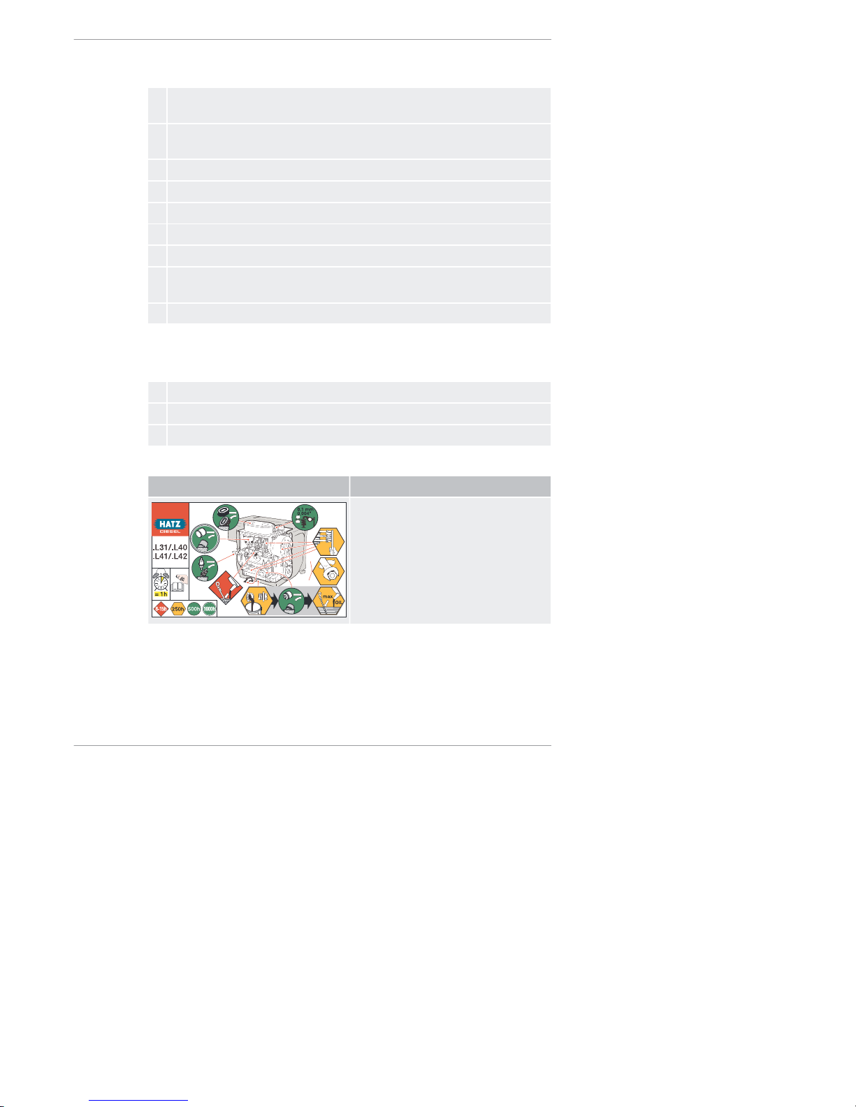
NOTICE
i
Depending on the engine type, one of the maintenance plans
shown below is supplied with the engine.
▪ It should be mounted on the engine or machine in a clearly
visible location.
▪ The maintenance intervals specified on the maintenance
plan must be adhered to (see the chapter 8.2.2 Maintenance plan, page 58).
Maintenance 2-4L41C, 2-4M41, 2-4M41Z, 4L42C, 4M42
56 Operator's Manual
HATZ
Page 57

2M41. Without oil sump
2M31
2M40
2M41
500h
250h
= 1h
max
OIL
0,1 mm
0.004"
max
2M41. Wit h oi l sump; 3-4M41. an d 4M42 in general
.M31/.M40
.M41/.M42
500h
250h
= 1h
max
OIL
0,1 mm
0.004"
max
2-4L41C, 2-4M41, 2-4M41Z, 4L42C, 4M42 Maintenance
HATZ
Operator's Manual 57
Page 58
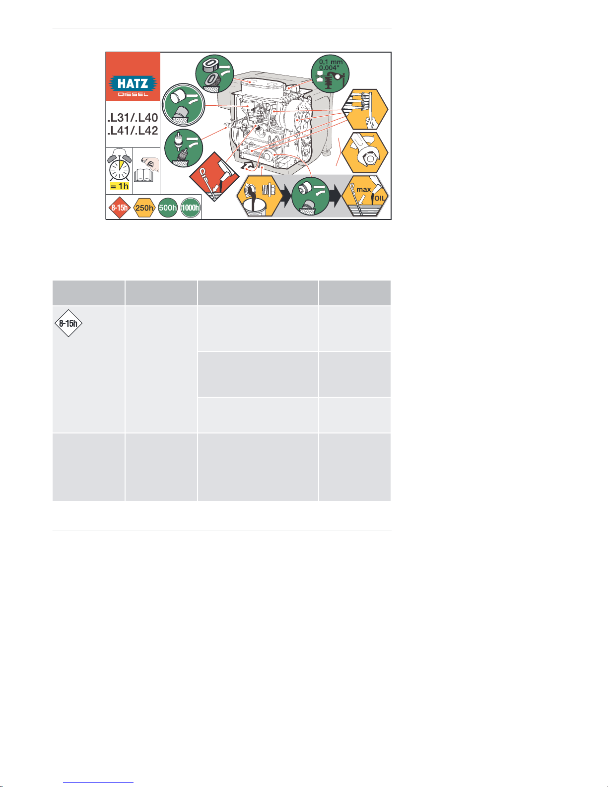
2-4L41C; 4L42C
max
OIL
8.2.2 Maintenance plan
The degree of contamination of the fuel, the care with which refueling is performed and the soiling on the inside of the fuel tank are decisive in determining the change interval of the fuel prefilter and the fuel filter.
Symbol Maintenance in-
terval
Maintenance activity/check Chapter
Every 8–15 operating hours or every day before
starting
Check the oil level. 7.9 Checking the
oil level and adding oil if necessary, page 53
Check the intake area of the
combustion air.
8.2.3 Checking
the intake area of
the combustion
air, page 60
Check the cooling air area. 8.2.4 Checking
the cooling air
area, page 63
Visual check of the condition
of the crankhandle (handle
bar, crank arm, drive dog)
If necessary, lightly grease
gliding area between crankhandle and guide sleeve.
−
Maintenance 2-4L41C, 2-4M41, 2-4M41Z, 4L42C, 4M42
58 Operator's Manual
HATZ
Page 59

Symbol Maintenance in-
terval
Maintenance activity/check Chapter
250h
Every 250 operating hours
Change the engine oil (2M41.
wi tho ut oil sump, 2-4L41C
and 4L42C in general).
8.2.5 Change the
engine oil,
page 64
Clean the cooling fan, cooling
fins and oil cooler.
8.2.6 Cleaning
the cooling fan,
cooling fins and
oil cooler,
page 66
Check the screw connections. 8.2.7 Checking
the screw connections,
page 70
Clean the screen insert in the
exhaust pipe.
8.2.8 Cleaning
the screen insert
in the exhaust
pipe (additional
equipment),
page 70
Checking the water separator. 7.8 Checking the
water separator,
page 51
Check the fuel prefilter for
contamination and change it if
necessary.
8.2.9 Changing
the fuel prefilter,
page 72
Check the air filter maintenance indicator.
8.2.15 Checking
that the air filter
maintenance indicator is working
properly,
page 87
500h
Every 500 operating hours
Change the fuel prefilter. 8.2.9 Changing
the fuel prefilter,
page 72
Maintain the dry air filter.
Change the filter cartridge.
8.2.10 Maintaining the dry air filter, page 74
Check and set the tappet
clearance.
8.2.12 Check and
set the tappet
clearance,
page 78
2-4L41C, 2-4M41, 2-4M41Z, 4L42C, 4M42 Maintenance
HATZ
Operator's Manual 59
Page 60

Symbol Maintenance in-
terval
Maintenance activity/check Chapter
Change the engine oil (2M41.
wi th oil sump, 3-4M41. and
4M42 in general).
8.2.5 Change the
engine oil,
page 64
Changing the oil filter. 8.2.13 Changing
the oil filter,
page 82
Every 1000 operating hours
Change the fuel filter. 8.2.14 Change
the fuel filter,
page 83
In new and generally overhauled engines, after 25 operating hours:
▪ Change the engine oil
▪ Check the tappet clearance and adjust if necessary
▪ Check the screw connections (do not retighten the screws for attaching
the cylinder head)
In case of a low number of operating hours, change the engine oil no later
than every 12 months, regardless of the actual number of operating hours.
8.2.3 Checking the intake area of the combustion air
Safety notes
CAUTION
Danger of burns.
There is a danger of burns when working on a hot engine.
▪ Let the engine cool.
▪ Wear safety gloves.
NOTICE
i
In case of heavy contamination, shorten the maintenance intervals accordingly (see the chapter 8.2.2 Maintenance plan,
page 58).
Maintenance 2-4L41C, 2-4M41, 2-4M41Z, 4L42C, 4M42
60 Operator's Manual
HATZ
Page 61

Overvi ew
2-4M41 and 4M42
3
2-4L41C and 4L42C
Pos. Desig nati on
1 Intake opening for combustion air
2 Dust outlet opening
3 Cyclone (option)
Procedure
Step Activity
1 Check the intake opening (1) for coarse contamination such as
leaves, heavy dust deposits, etc., and clean if necessary.
2 Check that the dust outlet opening (2) at the bottom of the cy-
clone precleaner is clear.
3 If the dirt contamination is oily, remover the cyclone (3) and
clean it.
2-4L41C, 2-4M41, 2-4M41Z, 4L42C, 4M42 Maintenance
HATZ
Operator's Manual 61
Page 62

Electrical air filter maintenance display
2-4L41C and 2-4M41 4L42C and 4M42
Pos. Desig nati on
5 Air filter maintenance display
Mechanical air filter maintenance display
Pos. Desig nati on
1 Red field
Procedure
Step Activity
For the electrical air filter maintenance display:
Maintenance 2-4L41C, 2-4M41, 2-4M41Z, 4L42C, 4M42
62 Operator's Manual
HATZ
Page 63

Step Activity
1 Briefly let the engine run at maximum speed and watch for the
indicator (5) to light up for a short period – depending on the
version.
In the engines 4L42C and 4M42, the following flash code indicates that maintenance work is required on the air filter
▪ 7 short flashes (approx. 0.5 seconds) and
▪ 1 long flash (approx. 1.5 seconds)
(see the chapter 8.2.10 Maintaining the dry air filter,
page 74).
Wit h mec hanical air fil ter mai nten ance displ ay:
1 Briefly let the engine run at maximum speed and watch for the
visible red field (1) in the mechanical air filter maintenance display.
The visible red field (1) indicates that maintenance work is required on the air filter (see the chapter 8.2.10 Maintaining the
dry air filter, page 74).
8.2.4 Checking the cooling air area
Safety notes
CAUTION
Danger of burns.
There is a danger of burns when working on a hot engine.
▪ Let the engine cool before maintenance.
CAUTION
Danger of injury.
When working with compressed air, foreign bodies may fly into
your eyes.
▪ Wear safety goggles.
▪ Never direct the compressed air jet toward people or toward
yourself.
2-4L41C, 2-4M41, 2-4M41Z, 4L42C, 4M42 Maintenance
HATZ
Operator's Manual 63
Page 64

CAUTION
Danger of engine damage from overheating.
The engine temperature display (option) lights up as soon as the
engine becomes impermissibly hot.
▪ Switch off the engine immediately and eliminate the cause.
NOTICE
i
In case of heavy contamination, shorten the maintenance intervals accordingly (see the chapter 8.2.2 Maintenance plan,
page 58).
Procedure
Step Activity
1 Check the supply and exhaust air areas for coarse contamina-
tion such as leaves, heavy dust deposits, etc., and clean if
necessary (see the chapter 8.2.6 Cleaning the cooling fan,
cooling fins and oil cooler, page 66).
8.2.5 Change the engine oil
Safety notes
CAUTION
Danger of burns.
When working on the engine there is a danger of burns from hot
oil.
▪ Wear personal protective equipment (gloves).
▪ Collect the used oil and dispose of it according to local envi-
ronmental regulations.
NOTICE
i
▪ The engine must be level.
▪ The engine must be switched off.
▪ Only drain engine oil while it is warm.
▪ The engine oil should be changed when the oil filter is
changed.
Maintenance 2-4L41C, 2-4M41, 2-4M41Z, 4L42C, 4M42
64 Operator's Manual
HATZ
Page 65

Overvi ew
M41 L41
Pos. Desig nati on
1 Oil drain screw
2 Drain pipe
Draining the oil
Step Activity
1 Unscrew the oil drain screw (1) and drain the oil entirely.
When unscrewing the oil drain screw (1) on engines of type
2-4L41C and 4L42C, ensure that the drain pipe (2) is not loosened. Hold it with an open-end wrench.
2 Screw in the cleaned oil drain screw (1) with the new gasket
and tighten.
Overvi ew
2-4L41C, 2-4M41, 2-4M41Z, 4L42C, 4M42 Maintenance
HATZ
Operator's Manual 65
Page 66

Pos. Designation
1 Dipstick
2 Mark on the dipstick
Adding oil
Step Activity
1 Add engine oil to the max. mark on the dipstick (1).
▪ For the specification and viscosity, see the chapter 4.3 En-
gine oil, page 24.
▪ The mark of the dipstick (2) indicates whether the engine is
equipped with an oil sump or no t (see the chapter 4.1 Engine, page 22).
2 Reinsert the dipstick (1).
3 Check the oil level after a short test run and correct if necessa-
ry.
8.2.6 Cleaning the cooling fan, cooling fins and oil cooler
Safety notes
DANGER
Danger of explosion from flammable cleaning agents.
Cleaning with benzene is an explosion hazard. It is highly flammable, can become electrostatically charged and can generate
an explosive gas-air mixture.
▪ Use halogen-free, cold cleaners with a high flashpoint for
cleaning.
CAUTION
Danger of burns.
There is a danger of burns when working on a hot engine.
▪ Let the engine cool before maintenance.
Maintenance 2-4L41C, 2-4M41, 2-4M41Z, 4L42C, 4M42
66 Operator's Manual
HATZ
Page 67

CAUTION
Danger of injury.
When working with compressed air, foreign bodies may fly into
your eyes.
▪ Wear safety goggles.
▪ Never direct the compressed air jet toward people or toward
yourself.
CAUTION
Danger of engine damage from overheating.
The engine temperature display (option) lights up as soon as the
engine becomes impermissibly hot.
▪ Switch off the engine immediately and eliminate the cause.
CAUTION
Danger of damage to the machine from incorrect engine
cl eanin g.
▪ Do not spray components of the electrical equipment with a
water jet or high pressure jet during cleaning.
▪ Do not use gasoline or acid-based cleaning agents.
CAUTION
Damage from inadequate engine cooling.
Only operate the engine when all covers are installed.
NOTICE
i
In case of heavy contamination, shorten the maintenance intervals accordingly (see the chapter 8.2.2 Maintenance plan,
page 58).
2-4L41C, 2-4M41, 2-4M41Z, 4L42C, 4M42 Maintenance
HATZ
Operator's Manual 67
Page 68

Overvi ew — Preparator y activiti es
Pos. Desig nati on
1 Baffle plate
Preparat ion
Step Activity
1 Unscrew the following on encapsulated engines:
▪ Hood
▪ Side wall with speed control lever
▪ Cover plate on operating side
▪ Exhaust air duct
▪ Cover plate on exhaust side
(see the chapter 5 Engine design, page 25).
1 Remove the following on engines without a capsule:
▪ Side trim panel
▪ Cooling air guide for lubrication oil cooler
2 Unscrew the baffle plate (1)
Maintenance 2-4L41C, 2-4M41, 2-4M41Z, 4L42C, 4M42
68 Operator's Manual
HATZ
Page 69

Overview — Cleaning
Procedu re — Cleaning
Step Activity
Cleaning in case of dry dirt contamination
1 Clean the cooling fan, cylinder head and cylinder with a suita-
ble brush.
2 Blow out the entire cooling air area with compressed air.
3 Blow out the oil cooler with compressed air only.
NOTE:
▪ Do not place the compressed air gun against the sensitive
radiator fins.
4 On encapsulated engines, also clean the area between the
floor plate and crankcase.
5 Mount the capsule and air guide parts again.
Cleaning of wet or oily dirt contamination
1 Disconnect the negative terminal of the battery.
2 Manually clean the alternator and regulator.
3 Cover the alternator with the installed regulator and do not
spray directly.
4 Spray the entire area with a suitable cleaning solution accord-
ing to manufacturer instructions and then clean off with a jet of
water.
Do not spray components of the electrical equipment with a
water jet or high pressure jet during cleaning.
5 Blow dry the engine with compressed air.
2-4L41C, 2-4M41, 2-4M41Z, 4L42C, 4M42 Maintenance
HATZ
Operator's Manual 69
Page 70

Step Activity
6 Determine the cause of the oil contamination and have leaks
corrected by the HATZ servic e station.
7 Mount the capsule and air guide parts again.
8 Let the engine run warm to prevent rust formation.
8.2.7 Checking the screw connections
NOTICE
i
▪ Do not retighten the screws for attaching the cylinder head.
▪ The adjustment screws on the speed regulator and the in-
jection system are secured with locking varnish and are not
permitted to be tightened or adjusted.
▪ Only retighten loose screw connections. Screw connections
can be secured with thread locking adhesive or tightened to
a defined torque. Retightening tight screw connections can
cause damage.
Procedure
Step Activity
1 Check the condition of all screw connections and ensure that
they are tight (for exceptions, see note).
2 Tighten any lose screw connections.
8.2.8 Cleaning the screen insert in the exhaust pipe (additional
equipment)
Safety notes
CAUTION
Danger of burns.
There is a danger of burns when working on a hot engine.
▪ Let the engine cool before maintenance.
Maintenance 2-4L41C, 2-4M41, 2-4M41Z, 4L42C, 4M42
70 Operator's Manual
HATZ
Page 71

CAUTION
Danger of injury
There is a danger of injury when performing cleaning work at the
exhaust screen.
▪ Wear safety gloves.
NOTICE
i
Operation of the engine for a lengthy period without a load or
with only a small load can result in premature deposits on the
screen insert.
Shorten the maintenance interval accordingly.
Overvi ew
Pos. Desig nati on
1 Pipe clamp
2 Screen insert
Procedure
Step Activity
1 Release the pipe clamp (1) and remove it with the exhaust
pipe.
2 Remove deposits on the screen insert (2).
3 Check the screen insert for cracks or breakage, and replace if
necessary.
2-4L41C, 2-4M41, 2-4M41Z, 4L42C, 4M42 Maintenance
HATZ
Operator's Manual 71
Page 72

8.2.9 Changing the fuel prefilter
Safety notes
DANGER
Fire hazard from fuel.
Leaked or spilled fuel can ignite on hot engine parts and cause
serious burn injuries.
▪ Never refuel in the vicinity of open flames or sparks that can
cause ignition.
▪ Do not smoke.
▪ Do not spill fuel.
CAUTION
Danger of injury
Repeated contact with diesel fuel can cause chapped and
cracked skin.
▪ Wear safety gloves.
CAUTION
Danger of environmental damage from spilled fuel.
When the filter is removed, a small amount of fuel is drained as
well.
▪ Collect emerging fuel and dispose of it in an environmentally
compatible manner.
CAUTION
Dirt particles can damage the injection system.
▪ Maintain clean conditions to ensure that dirt does not enter
the fuel line.
Maintenance 2-4L41C, 2-4M41, 2-4M41Z, 4L42C, 4M42
72 Operator's Manual
HATZ
Page 73

Overvi ew
Pos. Desig nati on
1 Fuel lines
2 Fuel prefilter
Procedure
Step Activity
1 Place a suitable container under the filter to collect emerging
fuel.
2 Close the fuel feed line.
3 Pull the fuel lines (1) off of the fuel prefilter (2) on both sides.
4 Dispose of the old filter in accordance with local environmental
regulations.
5 Insert a new fuel prefilter.
Note the following:
▪ Arrow for flow direction
▪ Position of the fuel tank: HIGH or LOW
▪ Installation position/flow-through direction should be as verti-
cal as possible
6 Open the fuel feed line.
2-4L41C and 2-4M41
7 To simplify the starting procedure, it is recommended that you
pre-pump the fuel using the manual lever at the fuel feed pump
until you hear fuel flow back through the return line into the fuel
tank (see the chapter 7.3.1 Pumping fuel with the manual lever, page 34).
8 Perform a leak tightness test by activating the manual lever.
2-4L41C, 2-4M41, 2-4M41Z, 4L42C, 4M42 Maintenance
HATZ
Operator's Manual 73
Page 74
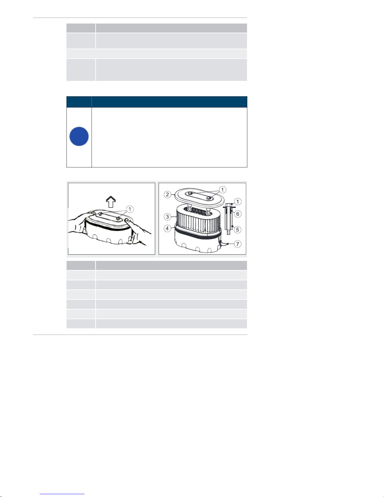
Step Activity
9 After completion, insert the access cover to the fuel feed pump
back in the side wall.
4L42C an d 4M42
7 If you have difficulties starting the engine, bleed the injection
system with the aid of the manual fuel pump (see the chapter
7.3.2 Pumping fuel with the manual fuel pump, page 35).
8.2.10 Maintaining the dry air filter
NOTICE
i
▪ Immediately clean the filter cartridge if the maintenance dis-
play appears at maximum speed.
▪ The air filter cartridge either needs to be replaced, or
cleaned or checked depending on the degree of contamination.
▪ Renew the filter cartridge after a use period of 500 operating
hours.
▪ Four cylinder engines have two filter cartridges.
Overvi ew of eng ines 2-4 L41C and 4L42C
Pos. Desig nati on
1 Screw
2 Cover
3 Filter cartridge
4 Air filter housing
5 Spacer
6 Bushing
Maintenance 2-4L41C, 2-4M41, 2-4M41Z, 4L42C, 4M42
74 Operator's Manual
HATZ
Page 75

Pos. Desig nati on
7 Clamp
Remo vin g th e air filter cart rid ge - engines 2-4L 41C and 4L42C
Step Activity
1 Remove the capsule hood.
2 Remove adherent dirt in the area of the air filter housing (4).
3 Only loosen the screws (1) to the point where you can lift off
the complete air filter housing (4).
4 Cover the opening in the intake pipe to prevent ingress of dirt
and other foreign bodies.
5 On three cylinder engines, open the clamp (7).
▪ On three cylinder engines, the cover (2) is additionally held
by a clamp (7).
6 Open the air filter housing (4).
7 Take out the filter cartridge (3).
8 Clean the air filter housing (4) and cover (2).
9 Renew the bushing (6) if the spacer (5) is loose.
▪ The spacer (5) is connected with the screw (1) by the elastic
bushing (6) to ensure that it cannot fall into the intake pipe
during disassembly and assembly.
Overview of th e eng ines 2-4M41. and 4M42
Pos. Desig nati on
1 Clamp
2 Air filter housing cover
3 Screw
2-4L41C, 2-4M41, 2-4M41Z, 4L42C, 4M42 Maintenance
HATZ
Operator's Manual 75
Page 76

Pos. Desig nati on
4 Filter cover
5 Spacer
6 Bushing
7 Filter cartridge
8 Air filter housing
Remo vin g th e air filter cart rid ge - engines 2-4M41. and 4M42
Step Activity
1 Release the clamps (1) and remove the cover of the air filter
housing (2).
2 Remove adherent dirt in the air filter area.
3 Only loosen the screws (3) to the point where the filter cover
(4) can be removed with the filter cartridge (7).
4 Cover the opening in the intake pipe to prevent ingress of dirt
and other foreign bodies.
5 Clean the air filter housing cover (2), filter cover (4) and air fil-
ter housing (8).
6 Renew the bushing (6) if the spacer (5) is loose.
▪ The spacer (5) is connected with the screw (3) by the elastic
bushing (6) to ensure that it cannot fall into the intake pipe
during disassembly and assembly.
8.2.11 Checking and cleaning the air filter cartridge
Safety notes
CAUTION
Danger of injury.
When working with compressed air, foreign bodies may fly into
your eyes.
▪ Wear safety goggles.
▪ Never direct the compressed air jet toward people or toward
yourself.
Maintenance 2-4L41C, 2-4M41, 2-4M41Z, 4L42C, 4M42
76 Operator's Manual
HATZ
Page 77
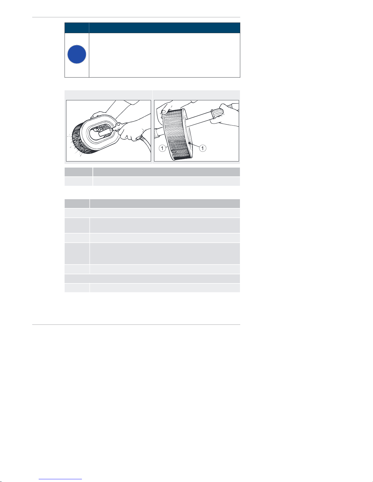
NOTICE
i
▪ The pressure must not exceed 5 bar.
▪ A distance of approx. 150 mm must be maintained between
the filter cartridge and the compressed air gun.
▪ Even minor damage in the areas of the sealing surface, filter
paper or filter cartridge makes it impossible to reuse the filter cartridge.
Overvi ew
Clean the filter cartridge Check the air filter cartridge
Pos. Desig nati on
1 Sealing surface
Procedure
Step Activity
Dry contamination
1 Blow out the filter cartridge with dry compressed air from the in-
side to the outside until dust no longer emerges.
2 Check the sealing surfaces (1) of the filter cartridge for damage.
3 Check the filter cartridge for cracks in the filter paper and other
damage by holding it against the light at a slant or letting light
from a lamp shine through it.
4 Replace the filter cartridge if necessary (see note).
Moist or oily contamination
1 Renew the filter cartridge.
2-4L41C, 2-4M41, 2-4M41Z, 4L42C, 4M42 Maintenance
HATZ
Operator's Manual 77
Page 78
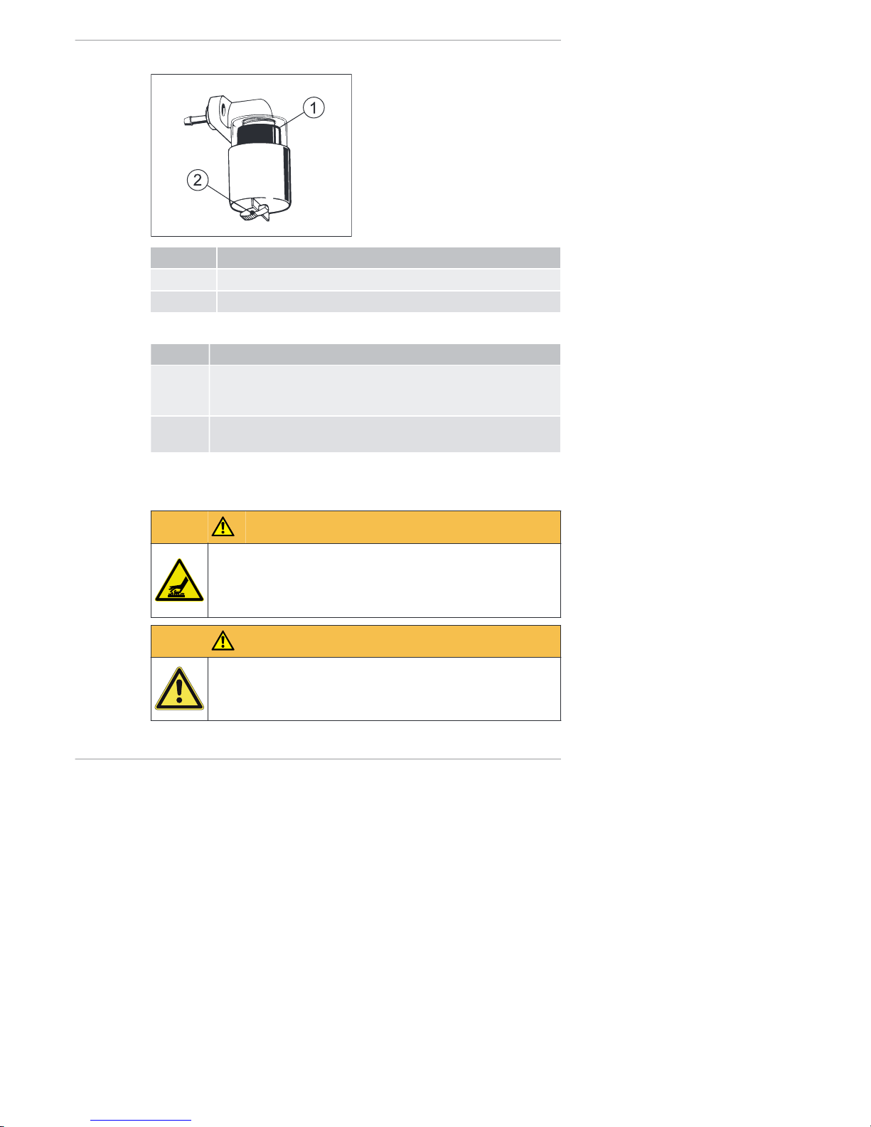
Mechanical air filter maintenance display
Pos. Desig nati on
1 Red field
2 Reset button
Mounting the air filter cartridge
Step Activity
1 When assembling, mount the parts individually one after the oth-
er to make sure they are correctly seated and to ensure leak
tightness.
2 After the filter is mounted, unlock the visible red field (1) in the
maintenance display by pressing the reset button (2).
8.2.12 Check and set the tappet clearance
Safety notes
CAUTION
Danger of burns.
There is a danger of burns when working on a hot engine. Only
perform the settings while the engine is cold (10-30°C).
▪ Let the engine cool.
CAUTION
Damage from inadequate engine cooling.
Only operate the engine when all covers are installed.
Maintenance 2-4L41C, 2-4M41, 2-4M41Z, 4L42C, 4M42
78 Operator's Manual
HATZ
Page 79

Overvi ew — Preparator y activiti es
Pos. Desig nati on
1 Square opening
2 Hex nut
3 Cylinder head cover
Prep arati on — A dju sti ng t he tappet clearanc e
Step Activity
1 On encapsulated engines, remove the hood of the capsule (see
the chapter 5 Engine design, page 25).
2 Remove the hex nut (2) and remove the cylinder head cover (3).
3 Remove the air guide housing cover (see the chapter 5 Engine
design, page 25) or the belt guard.
4 Insert the ratchet or T-piece 1/2" with the required extension (1)
into the square opening.
NOTICE
i
Turn the engine in the sense of rotation.
Anti-clockwise in both cases - flywheel side or timing cover side.
2-4L41C, 2-4M41, 2-4M41Z, 4L42C, 4M42 Maintenance
HATZ
Operator's Manual 79
Page 80

Numbering of the valves and cylinders from the fan side
1
2
3
4
12 345678
Setting method for two cylinder engine
Step Activity
1 Set the valve of the 1st cylinder – fan side – to overlap (outlet
valve not yet closed, intake valve begins to open).
2 Turn the crankshaft by 180° in the sense of rotation and check
the valves of the 2nd cylinder.
3 Continue turning the crankshaft by 180° in the sense of rotation
and check the valves of the first cylinder.
Setting method for three and four cylinder engines
Typ e Valve no . ... fully
opened
Check the valves of
the ... cy linder
3-cylinder
1
5
3
3rd cylinder
2nd cylinder
1st cylinder
4th cylinder
1
5
7
3
3rd cylinder
4th cylinder
2nd cylinder
1st cylinder
Maintenance 2-4L41C, 2-4M41, 2-4M41Z, 4L42C, 4M42
80 Operator's Manual
HATZ
Page 81

Overview — Adjusting the tappet c learance
Pos. Desig nati on
1 Hex nut
2 Adjusting screw
3 Feeler gauge
Procedu re — Ad jus ting the tappet clear ance
Step Activity
1 Check the tappet clearance with the feeler gauge (3). For the
setting, see the chapter 4 Technical data, page 22.
2 If the tappet clearance needs to be corrected:
▪ Release the hex nut (1).
▪ Turn the adjustment screw (2) so the feeler gauge (3) can be
pulled through with a barely perceptible resistance after the
hex nut (1) is tightened again.
3 Repeat the above procedure for the entire valve area, taking
special care to use the described adjustment method.
4 Mount the cylinder head cover again:
▪ Always renew the gaskets.
▪ Use the fixing nuts for the cylinder head cover no more than
twice before renewing them.
▪ Tightening torque: 10 Nm.
5 Mount all covers.
NOTE:
▪ Under no circumstances is the engine permitted to be operat-
ed if not all covers are mounted.
2-4L41C, 2-4M41, 2-4M41Z, 4L42C, 4M42 Maintenance
HATZ
Operator's Manual 81
Page 82

Step Activity
6 After a brief trial run, check the cylinder head cover for tight-
ness.
8.2.13 Changing the oil filter
Safety notes
CAUTION
Danger of burns.
When working on the engine there is a danger of burns from hot
oil.
▪ Wear personal protective equipment (gloves).
▪ Collect the used oil and dispose of it according to local envi-
ronmental regulations.
Overvi ew
Procedure
Step Activity
1 Release the oil filter with a strap wrench and quickly unscrew
and remove it.
▪ HATZ order no. for strap wrench: 620 307 01.
2 Dispose of the old filter in accordance with local environmental
regulations.
3 Wipe spilled engine oil out of the oil baffle.
4 Lightly oil the sealing lip of the new oil filter.
5 Screw in the oil filter and tighten it by hand.
Maintenance 2-4L41C, 2-4M41, 2-4M41Z, 4L42C, 4M42
82 Operator's Manual
HATZ
Page 83

Step Activity
6 Add engine oil to the m ax. mark on the dipstick.
▪ For the specifications and viscosity, see the chapter 4.3 En-
gine oil, page 24.
▪ The mark on the dipstick indicates whether the engine is
equipped with an oil sump or not (see the chapter 4.1 Engine, page 23).
7 Reinsert the dipstick.
8 Check the oil level after a short test run and correct if necessary.
9 Check the oil filter for tightness and retighten by hand if neces-
sary.
8.2.14 Change the fuel filter
Safety notes
DANGER
Fire hazard from fuel
Leaked or spilled fuel can ignite on hot engine parts and cause
serious burn injuries.
▪ Do not spill fuel.
▪ No open flames when working on the fuel system.
▪ Do not smoke
CAUTION
Danger of injury
Repeated contact with diesel fuel can cause chapped and
cracked skin.
▪ Wear safety gloves.
2-4L41C, 2-4M41, 2-4M41Z, 4L42C, 4M42 Maintenance
HATZ
Operator's Manual 83
Page 84
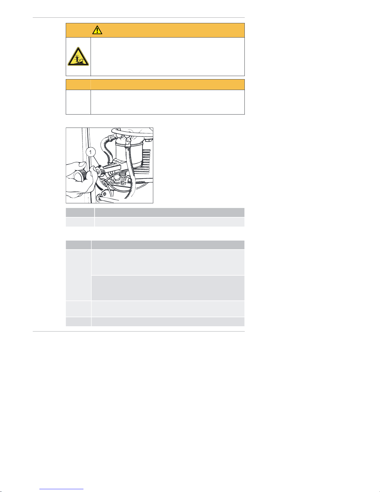
CAUTION
Danger of environmental damage from spilled fuel.
When the filter is removed, a small amount of fuel is drained as
well.
▪ Collect emerging fuel and dispose of it in an environmentally
compatible manner.
CAUTION
Dirt particles can damage the injection system.
▪ Maintain clean conditions to ensure that dirt does not enter
the fuel line.
Overview 2-4L41C and 2-4M41.
Pos. Desig nati on
1 Strap wrench (HATZ order no.: 620 307 01)
Proced ure 2-4L41C and 2-4M41
Step Activity
1 On encapsulated engines:
▪ Lift off the capsule hood
(see the chapter 5 Engine design, page 25).
On engines without a capsule:
▪ Remove the side trim panel
(see the chapter 5 Engine design, page 25).
2 Place a suitable container under the filter to collect emerging
fuel.
3 Close the fuel feed line.
Maintenance 2-4L41C, 2-4M41, 2-4M41Z, 4L42C, 4M42
84 Operator's Manual
HATZ
Page 85

Step Activity
4 Slide on the strap wrench (1) and unscrew the fuel filter counter-
clockwise.
5 Dispose of the old filter in accordance with local environmental
regulations.
6 Lightly oil the gasket of the new fuel filter.
7 Mount the fuel filter and tighten it by h and.
8 Open the fuel feed line.
9 To ease the starting procedure, it is recommended that you pre-
pump the fuel using the manual lever at the fuel feed pump until
you hear fuel flow back through the return line into the fuel tank
(see the chapter 7.3.1 Pumping fuel with the manual lever,
page 34).
10 Perform a leak tightness test by activating the manual lever.
11 After completion, insert the access cover to the fuel feed pump
back in the side wall.
12 Mount the capsule and air guide parts again.
Overvi ew 4L42C and 4M42
Pos. Desig nati on
1 Drain plug
Prep arati on 4L42C an d 4M42
Step Activity
1 Close the fuel lines on the filter housing.
2 Place a suitable container under the filter to collect emerging
fuel.
2-4L41C, 2-4M41, 2-4M41Z, 4L42C, 4M42 Maintenance
HATZ
Operator's Manual 85
Page 86

Step Activity
3 Release the drain screw (1) and drain the fuel.
Overvi ew 4L42C and 4M42
Pos. Desig nati on
1 Strap wrench (HATZ order no.: 620 307 01)
2 Gasket
Procedu re 4L42 C and 4M42
Step Activity
1 Slide on the strap wrench (1) and unscrew the fuel filter counter-
clockwise.
2 Dispose of the old filter in accordance with local environmental
regulations.
3 Lightly oil the gasket (2) of the new fuel filter.
4 Mount the fuel filter and tighten it by h and.
5 Open the fuel feed line.
6 Bleed the injection system with the aid of the manual fuel pump
(see the chapter 7.3.2 Pumping fuel with the manual fuel pump,
page 35).
7 After a brief trial run, check the fuel filter for leak tightness and
retighten by hand.
Maintenance 2-4L41C, 2-4M41, 2-4M41Z, 4L42C, 4M42
86 Operator's Manual
HATZ
Page 87

8.2.15 Checking that the air filter maintenance indicator is working
properly
Overview
Electrical
air filter maintenance display
Mechanical
air filter maintenance display
Hose of air intake pipe
Pos. Designation
1 Red field
2 Reset button
3 Hose
5 Air filter maintenance display
Ignition lock
0 Off
I Operation
II Start
2-4L41C, 2-4M41, 2-4M41Z, 4L42C, 4M42 Maintenance
HATZ
Operator's Manual 87
Page 88

Procedure
Step Activity
1 Remove the capsule hood and the side panel trim (see the
chapter 5 Engine design, page 25).
2 Turn the starting key to position I.
3 Pull the hose (3) off of the exhaust manifold.
Electri cal air filter maint enance disp lay
NOTE:
On engine types 4L42 and 4M42, this function test cannot be
performed.
4 Generate a vacuum by sucking forcefully at the hose end.
The indicator (5) lights up.
5 If there is no reaction, check the following:
▪ Electrical part; cable connections, etc.
▪ Indicator
▪ Function of the maintenance switch.
Mechanical air filter maintenance display
4 Generate a vacuum by sucking forcefully at the hose end.
The red field (1) engages.
5 After the function test, unlock the red field (1) by pressing the re-
set button (2).
After the function test
6 Replace the faulty parts.
7 Reattach the hose (3) of the exhaust manifold.
8 Mount the capsule and air guide parts again.
Maintenance 2-4L41C, 2-4M41, 2-4M41Z, 4L42C, 4M42
88 Operator's Manual
HATZ
Page 89

8.2.16 Renewing the poly v belt and checking the function of the switchoff unit
NOTICE
i
When chan gin g the b elt:
▪ Always check the function of the switch-off unit. The switch-
off pin must emerge by spring force, or else the machine will
not switch off automatically if the belt tears.
▪ If the grooves are broken off or bent, renew the damaged
pulley.
▪ To be absolutely sure that you order the right poly v belt – in
terms of the length – it is recommended that you measure
the diameter of the fan-side pulley and use this as the basis
for your selection.
Belt types
Because of the different diameters of the fan-side pulleys, in combination
with different engine types and versions, various lengths of poly v belts are
used.
Type and engine
version
ID number Belt length mm Fan pulley
Ø mm
2L41C 502 031 00 920 72
All remaining types
and versions
501 415 00 910 64
Overview — Removing the poly v belt
Pos. Designation
1 Cylinder screw
2 Tension pulley
2-4L41C, 2-4M41, 2-4M41Z, 4L42C, 4M42 Maintenance
HATZ
Operator's Manual 89
Page 90

Pos. Designation
3 Pulley
Procedure — Removing the poly v belt
Step Activity
1 Unscrew one cylinder screw (1) from the pulley (3).
2 Push back the tension pulley (2) and lock it using the cylinder
screw (1).
3 Unscrew the pulley (3).
4 Check the pulley (3) for broken or bent grooves.
5 Remove the poly v belt.
Overview — Checking the function of the switch-off unit of the belt monitoring system
Pos. Designation
1 Tension pulley
2 Angle lever
3 Switch-off pin
Maintenance 2-4L41C, 2-4M41, 2-4M41Z, 4L42C, 4M42
90 Operator's Manual
HATZ
Page 91
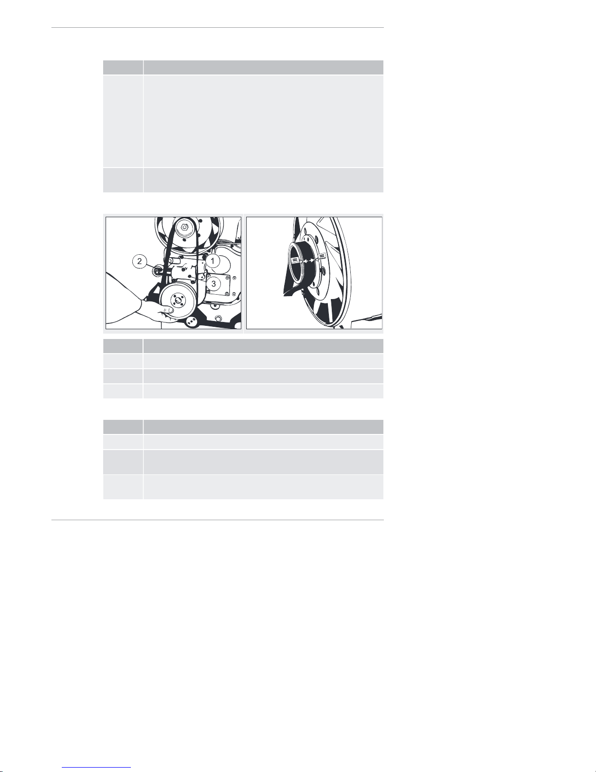
Procedure — Checking the function of the switch-off unit of the belt monitoring system
Step Activity
1 Release the piston with the tension pulley (1) by removing the
cylinder screw.
▪ The piston with the tension pulley is pushed out of the housing
by spring pressure.
▪ The angle lever (2) turns downward and releases the switch-
off pin (3).
▪ The switch-off pin (3) must emerge by spring force, or else the
machine will not switch off automatically if the belt tears.
2 If there is no reaction, please contact the nearest HATZ ser vice
station.
Overview — Mounting the poly v belt
Pos. Designation
1 Switch-off pin
2 Tension pulley
3 Housing
Procedure — Mounting the poly v belt
Step Activity
1 Slide in the switch-off pin (1).
2 Slide the piston with the tension pulley (2) into the housing (3)
and lock it using the cylinder screw.
3 Position the poly v belt centrally on the pulley of the fan wheel,
the tension pulley (2) and the pulley at the bottom.
2-4L41C, 2-4M41, 2-4M41Z, 4L42C, 4M42 Maintenance
HATZ
Operator's Manual 91
Page 92

Overview — Centering the pul ley
Pos. Designation
1 Cylinder screw
Procedure — Centering the pulley
Step Activity
1 Lightly secure the pulley with a cylinder screw (1) without plac-
ing the pulley fully on the centering.
2 Insert a large screwdriver between the hydraulic belt tensioner
and pulley and push down until it slides fully into the centering.
3 Insert the remaining cylinder screws (1) and tighten.
Maintenance 2-4L41C, 2-4M41, 2-4M41Z, 4L42C, 4M42
92 Operator's Manual
HATZ
Page 93

9 Faults
9.1 Troubleshooting
Troubleshooting notes
If the cases listed below have been worked through but the fault continues to
persist, please contact your nearest HATZ servi ce stati on.
Type of fault Possible causes Remed y Chapter
The engine does
not start or does
not start immediately, but it can be
turned with the
starter.
Move the speed
control lever to the
"STOP" position.
Depending on the
possibility or requirement, place
the lever in either
the 1/2 start or
max. START position. The lever
must be fixed in
this position.
7.4 Setting
the speed
control,
page 37
7.5 Starting
the engine,
page 37
No fuel at the injection pump.
Refuel. 7.7 Refuel-
ing, page 50
Activate the feed
pump until the fuel
can be heard to
flow back through
the return line into
the fuel tank.
7.3 Start
preparation,
page 34
Systematically
check the entire
fuel supply:
If this does not
yield results:
▪ Check the feed
line to the engine.
▪ Check the fuel
prefilter.
▪ Check the fuel fil-
ter.
▪ Check the func-
tion of the feed
pump.
8.2.9
Changing
the fuel prefilter,
page 72
8.2.14
Change the
fuel filter,
page 83
2-4L41C, 2-4M41, 2-4M41Z, 4L42C, 4M42 Faults
HATZ
Operator's Manual 93
Page 94

Type of fault Possible causes Remed y Chapter
After every extended period of disuse, if
you experience difficulties starting the
engine that can be eliminated by activating the feed pump for a lengthy period,
check that the fuel system is correctly
sized.
6.2 Assembly instructions,
page 31
Insufficient
compression:
▪ Wrong tappet
clearance.
Check the tappet
clearance and adjust if necessary.
8.2.12
Check and
set the tappet clearance,
page 78
▪ Cylinder and/or
piston ring wear.
Contact Hatz service.
▪ Faulty automatic
decompression.
Contact Hatz service.
Injection nozzle is
not functional.
Contact Hatz service.
Torn cooling fan
belt.
Renew the poly v
belt.
8.2.16 Renewing the
poly v belt
and checking the function of the
switch-off
unit,
page 89
At low temperatures
Pre glow system is
faulty (additional
equipment).
Contact Hatz service.
Fuel gelled due to
insufficient cold resistance.
Check whether the
fuel that emerges
from the detached
fuel feed line directly at the injection pump is clear
and not cloudy. If
the fuel has gelled,
either warm the engine or drain the
entire fuel supply
system. Fill with a
temperature-resistance fuel mixture.
4.2 Fuel,
page 23
7.7 Refueling, page 50
8.2.9
Changing
the fuel prefilter,
page 72
8.2.14
Change the
fuel filter,
page 83
Faults 2-4L41C, 2-4M41, 2-4M41Z, 4L42C, 4M42
94 Operator's Manual
HATZ
Page 95

Type of fault Possible causes Remed y Chapter
Starter speed is too
low:
▪ Oil is too vis-
cous.
Change the engine
oil and add oil of
the right viscosity
class.
4.3 Engine
oil, page 24
8.2.5
Change the
engine oil,
page 64
▪ Insufficiently
charged battery.
Check the battery
and contact the
service center if
necessary.
3.2.4 Electrical equipment,
page 18
Machine is not uncoupled.
If possible, separate the engine
from the machine
by uncoupling it.
The starter does
not switch on and
the engine does
not turn.
Irregularities in the
electrical equipment:
▪ Battery and/or
other cable connections are incorrectly connected.
▪ Cable connec-
tions are loose
and/or oxidized.
▪ Battery is faulty
and/or not loaded.
▪ Faulty starter.
▪ Faulty relay,
monitoring elements, etc.
Check the electrical equipment and
their components.
Contact Hatz service.
3.2.4 Electrical equipment,
page 18
The engine starts,
but does not continue running after
the starter is
switched off.
The speed control
lever is not sufficiently set to the
Start direction.
Set the lever to the
Start position.
7.5 Starting
the engine,
page 37
Machine is not uncoupled.
If possible, separate the engine
from the machine
by uncoupling it.
2-4L41C, 2-4M41, 2-4M41Z, 4L42C, 4M42 Faults
HATZ
Operator's Manual 95
Page 96

Type of fault Possible causes Remed y Chapter
Fuel prefilter is
clogged.
Change the fuel
prefilter.
8.2.9
Changing
the fuel prefilter,
page 72
Fuel filter is clogged.
Change the fuel filter.
8.2.14
Change the
fuel filter,
page 83
Fuel supply is interrupted.
Systematically
check the entire
fuel supply.
Stop signal from
monitoring elements that are associated with the
automatic switchoff (additional
equipment):
▪ No oil pressure.
▪ Dirty air filter
unit.
▪ Faulty three
phase alternator.
▪ Check the oil lev-
el.
▪ Check the de-
gree of dirt contamination of the
air filter, and
clean or renew it
if necessary.
▪ Contact Hatz
service.
7.9 Checking the oil
level and
adding oil if
necessary,
page 53
8.2.10
Maintaining
the dry air
filter,
page 74
Engine switches off
spontaneously during operation.
The tank ran out of
fuel during operation
Fill with fuel. 7.7 Refuel-
ing, page 50
Fuel prefilter or fuel
filter is clogged.
Change the filter. 8.2.9
Changing
the fuel prefilter,
page 72
8.2.14
Change the
fuel filter,
page 83
Faults 2-4L41C, 2-4M41, 2-4M41Z, 4L42C, 4M42
96 Operator's Manual
HATZ
Page 97

Type of fault Possible causes Remed y Chapter
Torn cooling fan
belt.
Renew the poly v
belt.
8.2.16 Renewing the
poly v belt
and checking the function of the
switch-off
unit,
page 89
Mechanical faults. Contact Hatz serv-
ice.
With automatic
electrical switch-off
mechanism
(additional equipment)
Stop signal of monitoring elements
for:
▪ Oil pressure too
low.
▪ Cylinder head
temperature too
high.
Check the engine
for:
▪ Engine oil filling
level
▪ Contamination of
the cooling air
guides or another impairment of
the cooling system.
7.9 Checking the oil
level and
adding oil if
necessary,
page 53
8.2.6 Cleaning the cooling fan,
cooling fins
and oil cooler, page 66
Irregularities in the
electrical equipment, such as:
▪ Loose contacts
on cable connections.
▪ Faulty three
phase alternator.
▪ Faulty relay.
Check the electrical equipment and
its components,
contacting the
service center if
necessary.
3.2.4 Electrical equipment,
page 18
The indicator for
the exhaust gas return system (EGR)
flashes (only on
4L42 and 4M42).
Air filter is dirty. Check the degree
of dirt contamination of the air filter,
and clean or renew
it if necessary.
8.2.10
Maintaining
the dry air
filter,
page 74
Problems with the
exhaust gas return
system.
Contact Hatz service.
2-4L41C, 2-4M41, 2-4M41Z, 4L42C, 4M42 Faults
HATZ
Operator's Manual 97
Page 98

Type of fault Possible causes Remed y Chapter
The engine loses
power and speed.
The fuel supply is
impaired
▪ The tank ran out
of fuel during operation.
▪ Fuel prefilter or
fuel filter is clogged.
▪ Inadequate tank
venting.
▪ Line connections
are not leak tight.
Add fuel.
Change the filter.
Ensure that the
tank is sufficiently
vented.
Check the line
screw connections
for leak tightness.
7.7 Refueling, page 50
8.2.9
Changing
the fuel prefilter,
page 72
8.2.14
Change the
fuel filter,
page 83
▪ The speed ad-
justment lever
does not stay in
the desired position.
Block the speed
adjustment.
The engine loses
power and speed,
and black smoke
emerges from the
exhaust.
Dirty air filter unit. Check the degree
of dirt contamination of the air filter,
and clean or renew
it if necessary.
8.2.10
Maintaining
the dry air
filter,
page 74
Tappet clearance
not OK.
Adjust the tappet
clearance.
8.2.12
Check and
set the tappet clearance,
page 78
Injection nozzle is
not functional.
Contact Hatz service.
Engine becomes
very hot.
Indicator lamp for
the cylinder head
temperature (additional equipment)
lights up.
Too much engine
oil in the engine.
Drain the engine oil
to the upper mark
of the dipstick.
7.9 Checking the oil
level and
adding oil if
necessary,
page 53
Faults 2-4L41C, 2-4M41, 2-4M41Z, 4L42C, 4M42
98 Operator's Manual
HATZ
Page 99

Type of fault Possible causes Remed y Chapter
Inadequate cooling:
▪ Contamination in
the entire area of
the cooling air
guides.
Clean the cooling
air area.
8.2.6 Cleaning the cooling fan,
cooling fins
and oil cooler, page 66
▪ Incompletely
closed air guide
parts or capsule
parts.
Check the air guide
parts and shafts for
completeness and
good sealing properties.
9.2 Emergency start
Electrical automatic shutoff (additional equipment)
The distinguishing feature of the electrical automatic shutoff is brief flashing
of all indicators after turning the starting key to position "I".
NOTICE
i
Note - If the engine stops again immediately after starting, or
stops independently during operation, this is an indication that a
monitoring element of the automatic shutoff has been activated
(see the chapter 9.1 Troubleshooting, page 93.
If the engine switches off due to an electrical fault signal or due to insufficient
oil pressure with the aid of the automatic switch-off, an emergency start can
be attempted by the user. The user must bear responsibility for any resulting
damage.
This may be necessary if the vehicle stops at a critical location (railroad
crossing or intersection).
When a monitoring element of the automatic switch-off is activated, the corresponding indicator lights up. After shutting down the engine, the indicator
remains lit for approx. 2 minutes. The electrical equipment then switches off
automatically.
Safety notes
CAUTION
Danger when switching off the engine from the emergency
operation mode.
During the emergency operation mode, the engine can only be
switched off with the starting key if the emergency start lever is
first returned to its home position.
2-4L41C, 2-4M41, 2-4M41Z, 4L42C, 4M42 Faults
HATZ
Operator's Manual 99
Page 100
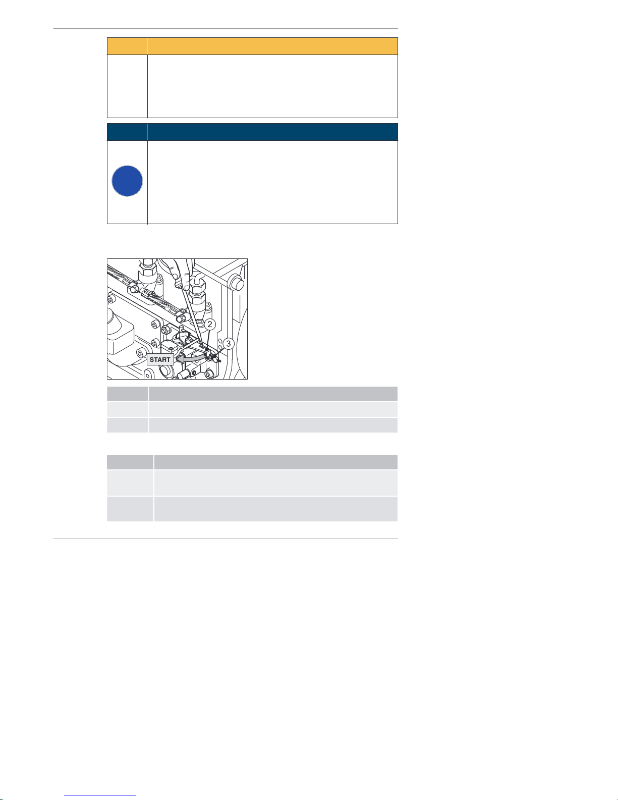
CAUTION
Danger of later engine damage.
The monitoring components (oil pressure, charge control and
engine temperature) are deactivated in emergency operation.
▪ The oil level must be checked before the emergency opera-
tion phase.
NOTICE
i
If the emergency operation mode is used, the risk transfers to
the operator (the Motor enfab rik HATZ does not accep t li abil ity in this case).
▪ Immediately after the emergency operation phase, deter-
mine the cause of the fault.
▪ Have the Hatz service st atio n supply the emergency start
lever with a new lead seal.
Overvi ew
Pos. Desi gnat ion
2 Emergency start lever
3 Seal wire
Procedure
Step Activity
1 Check the oil level (see the chapter 7.9 Checking the oil level
and adding oil if necessary, page 53).
2 Remove the capsule hood and the side panel trim (see the
chapter 5 Engine design, page 25).
Faults 2-4L41C, 2-4M41, 2-4M41Z, 4L42C, 4M42
100 Operator's Manual
HATZ
 Loading...