

Hatz Diesel 2W35, 3W35, 4W35, 4W35T Instruction Manual
433 916 01-USA-EPA IV-CARB
12.07-0.03
Printed in Germany
INSTRUCTION BOOK
33
INCLUDES SUPPLEMENTAL INFORMATION TO THE
OWNER’S MANUAL FOR 2008 AND LATER EPA CERTIFIED
NONROAD COMPRESSION-IGNITION ENGINES
INCLUDES SUPPLEMENTAL INFORMATION TO THE
OWNER’S MANUAL FOR 2008 AND LATER CALIFORNIA
REGULATIONS FOR HEAVY-DUTY OFF-ROAD ENGINES
2W35
3W35
4W35
4W35T
A new HATZ Diesel engine - working for you
This engine is intended only for the purpose determined and has been tested by the manufacturer of
the equipment in which it is installed. Using it in any other manner contravenes the intended purpose.
For danger and damage due to this, Motorenfabrik HATZ assumes no liability. The risk is with the
user only.
Use of this engine in the intended manner presupposes compliance with the maintenance and repair
instructions laid down for it. Noncompliance leads to engine breakdown.
Please do not fail to read this operating manual before starting the engine for the first time.
This will help you to avoid accidents, ensure that you operate the engine correctly and assist you
in complying with the maintenance intervals in order to ensure long-lasting, reliable performance.
Please follow all maintenance references carefully including the schedule for 2008 and later
EPA certified nonroad compression-ignition engines and for 2008 and later CARB certified
off-road engines to prevent our environment.
Please pass this Instruction Manual on to the next user or to the following engine owner.
The worldwide HATZ Service Network is at your disposal to advise you, supply with spare parts and
undertake servicing work.
You will find the address of your nearest HATZ service station in the enclosed list.
Use only original spare parts from HATZ. Only these parts guarantee a perfect dimensional stability
and quality. The order numbers can be found in the enclosed spare parts list. Please note the spare
parts kits shown in Table M00.
We reserve the right to make modifications in the course of technical progress.
MOTORENFABRIK HATZ GMBH & CO KG
1


Page
1. Important safety notes
when operating the engine 4
2. Description of the engine 6
3. General notes 10
3.1. Technical data 10
3.2. Transport 11
3.3. Instructions for installation 11
3.4. Load on engine 11
3.5. EPA/CARB-type plates 12
3.6. Emission-related installation
instructions 13
4. Operation 13
4.1. Before initial start-up 13
4.1.1. Engine oil 13
4.1.2. Coolant 14
4.1.3. Fuel 16
4.2. Starting the engine 18
4.2.1. Preparations for starting 18
4.2.2. Electric starter 19
4.3. Stopping the engine 20
5. Maintenance 22
5.1. Maintenance chart 22
5.2. Maintenance every 8 - 15
operating hours 24
5.2.1. Check engine oil level 24
5.2.2. Check combustion air intake area 24
5.2.3. Check air cleaner maintenance
indicator 25
5.2.4. Check radiator fins for contamination 25
5.2.5. Check coolant level 25
Page
5.3. Maintenance every 250
operating hours 26
5.3.1. Change engine oil 26
5.3.2. Check water trap 26
5.3.3. Clean the radiator fins 27
5.3.4. Check screw connections 28
5.3.5. Check the Vee belt 28
5.4. Maintenance every 500
operating hours 29
5.4.1. Replace primary fuel filter 29
5.4.2. Replace the engine oil filter 30
5.4.3. Air cleaner maintenance 31
5.5. Maintenance every 1000
operating hours 34
5.5.1. Renew the fuel filter 34
5.6. Maintenance: every 4 years 35
5.6.1. Replacement of coolant 35
6. Malfunctions – causes – remedies 37
7. Work on the electrical system 41
8. Storage out of use 41
SUPPLEMENTAL INFORMATION TO
THE OWNER’S MANUAL FOR 2008
AND LATER EPA CERTIFIED NONROAD
COMPRESSION IGNITION ENGINES 43
SUPPLEMENTAL INFORMATION TO
THE OWNER’S MANUAL FOR 2008
AND LATER CALIFORNIA
REGULATIONS FOR HEAVY-DUTY
OFF-ROAD ENGINES 57
3
Contents
This symbol identifies important safety precautions.
Please comply with these most carefully in order to avoid any risk of injury to persons or
damage to materials.
General legal requirements and safety regulations issued by the competent authorities or
industrial accident insurers must also be complied with.

1. Important safety notes when operating the engine
HATZ diesel engines are efficient, strong and durable. For this reason they are mostly installed on
equipment used for commercial purposes.
The manufacturers of such equipment must observe any relevant equipment safety regulations when
the engine forms part of an overall system.
A few general points concerning operating safety should nonetheless be noted.
Depending on the engine's operating and installation conditions, equipment manufacturers and their
users may have to fit safety or protective devices in order to prevent improper use. Examples:
– Exhaust system components as well as the surface of the engine will naturally be hot and must not
be touched while the engine is running or until it has cooled down after being stopped.
– Incorrect wiring or improper operation of the electrical system may cause sparking and must there-
fore be avoided.
– Provide protection against contact with rotating parts once the engine is connected to the driven
equipment or machine.
HATZ protective guards are available for the belt drive of the cooling fan and alternator drive
systems.
– Always observe the start-up information in the operating instructions before starting the engine.
– Mechanical starting devices should not be operated by children or persons deficient in physical
strength.
– Check that all safety devices are in place before starting the engine.
– Ensure that operation, maintenance and repair of the engine are undertaken by suitably trained
personnel only.
– Protect the starter key against unauthorised use.
– Do not run the engine in closed or insufficiently ventilated rooms.
Do not breathe in emissions – danger of poisoning!
– Also fuel and lubricants could contain poisonous components. Please follow the appropriate
instructions of the mineral oil producer.
– Radiator protection fluids are detrimental to health. Thus, they may only be stored in closed original
containers and in a place inaccessible to non-authorized persons. Eye and skin contact must be
avoided. Comply with the manufacturer’s instructions
4

Important safety notes when operating the engine
– The engine must be stopped before performing any maintenance, cleaning or repair work.
– It is essential to stop the engine before refilling the fuel tank.
Never refuel near a naked flame or sparks which could start a fire. Don’t smoke. Don’t spill fuel.
– Keep explosive materials as well as flammable materials away from the engine because the exhaust
gets very hot during operation.
– Never spill consumables, such as fuel, oil or radiator protection fluid over hot engine components.
The fluid might catch fire.
– Work on the cooling system must not be performed while the engine is warm - risk of scalding !
The cooling system is pressurized.
– Wear close-fitting clothing only when working on the engine while it is running.
Please don’t wear necklaces, bracelets or any other objects which you could get caught with.
– Please pay attention to all advice- and warning stickers placed on the engine and keep them in
legible condition. Contact your next HATZ service station if a sticker comes off or is illegible and
ask for a new one.
– We accept no liability for damage resulting from improper modifications to the engine.
Regular servicing in accordance with the details provided in this Instruction Book is essential to keep
the operating reliably and to ensure the exhaust quality of the engine.
When in doubt, consult your local HATZ service station before starting the engine.
5

2. Description of the engine 2 W35 • 3 W 35 • 4W 35
6
M
O
T
O
R
E
N
F
A
B
R
I
K
H
A
T
Z
K
G
D
-
9
4
0
9
9
R
U
H
S
T
O
R
F
M
A
D
E
I
N
G
E
R
M
A
N
Y
11
17
16
15
13
12
1
2
3
4
5
6
7
8
10
9
14
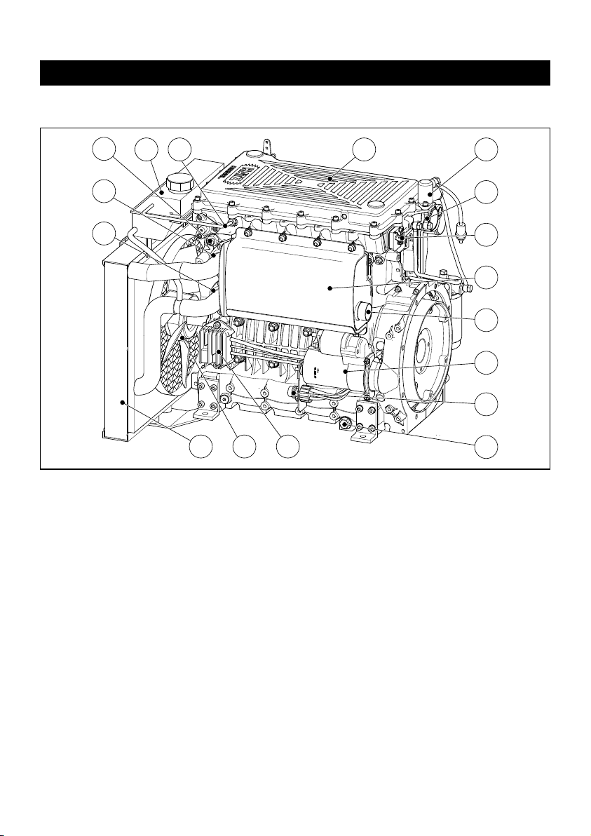
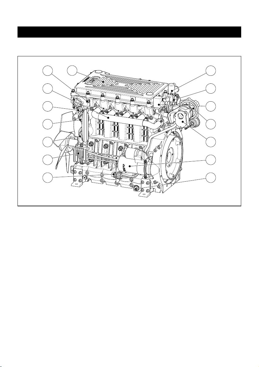
1 Operator’s side
1 Speed adjustment lever
2 Type plate
3 Coolant pump
4 Oil dipstick
5 Oil filler cap
6 Drain plug for coolant
7 Oil drain plug (governor side)
8 Engine mountings (optional equipment)
9 Oil drain plug (operator’s side)
10 Engine oil filter
11 Water drain plug on fuel filter
12 Oil pressure switch
13 Fuel filter with water trap
14 Dry-type air cleaner
15 Combustion air intake port
16 Fuel suction line connector
17 Fuel pre-filter
Description of the engine 2 W 35 • 3W 35 • 4 W35
7
1 Fuel feed pump
2 Fuel return line
3 Stop lever (optional equipment)
4 Exhaust silencer
5 Exhaust gas outlet
6 Electrical starter
7 Central plug for electrical system
8 Oil drain plug (exhaust side)
9 Voltage regulator
10 Fan (optional equipment)
11 Radiator (optional equipment)
12 Coolant supply to engine
13 Coolant return to radiator and thermostat
14 Temperature switch
15 Coolant expansion tank (optional
equipment)
16 Vent line to expansion tank
17 Cylinder head cover
1
2
3
4
5
6
7
8
11
14
13
12
9
15 16
10
17
2 Exhaust side
Description of the engine 4 W 35T (turbocharged engine)
8
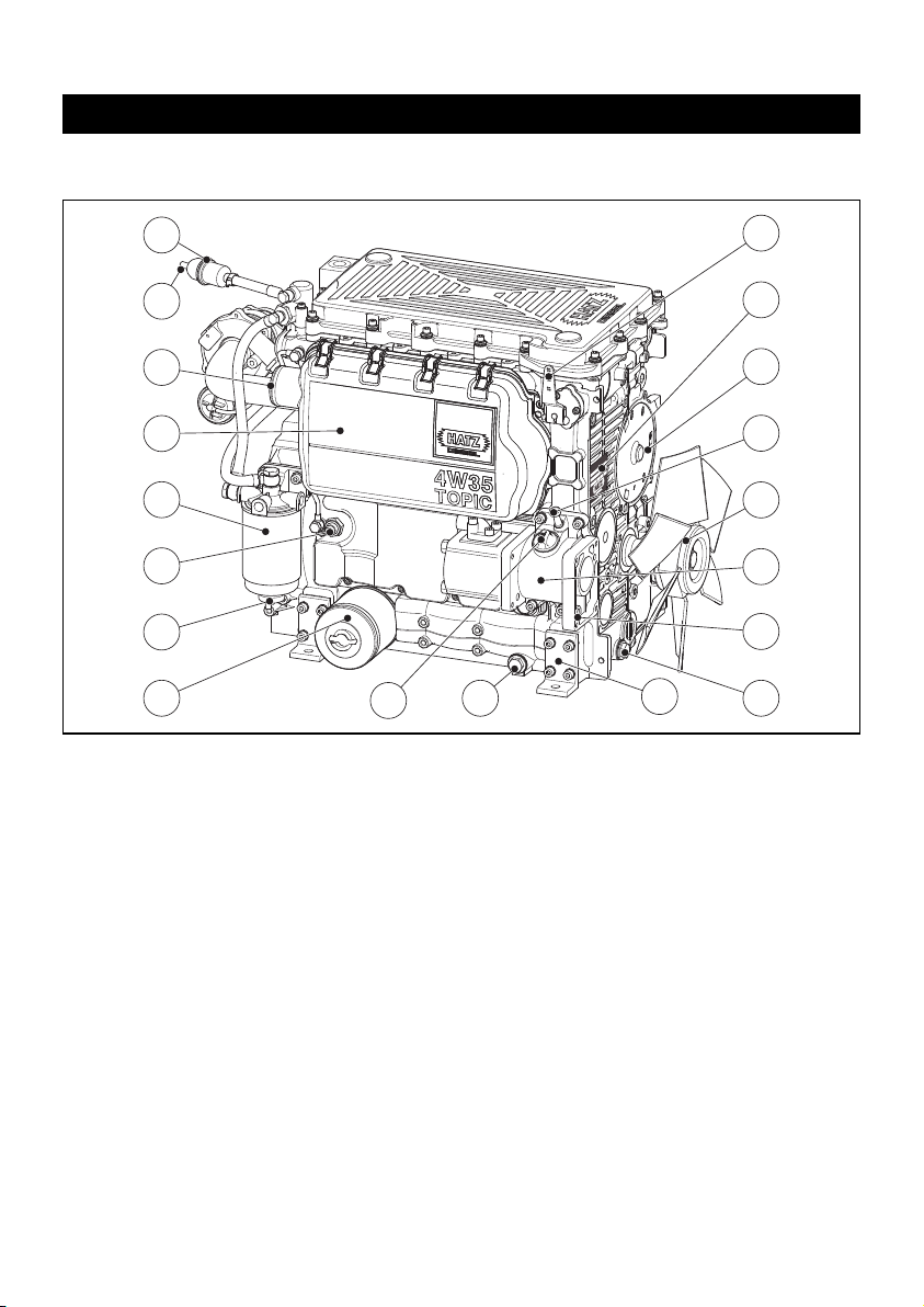
3 Operator’s side
1 Speed adjustment lever
2 Type plate
3 Coolant pump
4 Oil dipstick
5 Fan (optional equipment)
6 Hydraulic pump drive (optional equipment)
7 Flange for additional hydraulic pump
(optional equipment)
8 Oil drain plug (governor side)
9 Engine mountings (optional equipment)
10 Oil drain plug (operator’s side)
11 Oil filler cap
12 Engine oil filter
13 Water drain plug on fuel filter
14 Oil pressure switch
15 Fuel filter with water trap
16 Dry-type air cleaner
17 Combustion air intake port
18 Fuel suction line connector
19 Fuel pre-filter
19
18
17
16
15
14
13
12
11
10
G
K
Z
T
A
H
F
K
R
I
O
R
T
B
S
A
H
F
U
N
R
E
R
9
9
O
0
T
4
O
9
-
M
D
Y
N
A
M
R
E
G
N
I
E
D
A
M
9
1
2
3
4
5
6
7
8
9
Description of the engine 4 W 35T (turbocharged engine)
1 Fuel feed pump
2 Fuel return line
3 Stop lever or stop solenoid
(optional equipment)
4 Turbocharger
5 Exhaust flange
6 Electric starter
7 Oil drain plug (exhaust side)
8 Central plug for electrical system
9 Voltage regulator
10 Coolant supply to engine
11 Coolant return to radiator and thermostat
12 Temperature switch
13 Exhaust manifold
14 Connector for vent line to expansion tank
(coolant)
15 Cylinder head cover
3
4
5
6
7
1
2
14
12
11
10
9
8
15
13
4 Exhaust side

10
3. General notes
3.1. Technical data
1)
These values are intended as an approximate guide. The max. marking on the dipstick is the
determining factor.
2)
Exceeding these limits causes engine breakdown.
Type 2W35 3W35 4W35 4W35 T
Design Fluid-cooled four-stroke diesel engine
Combustion air normal intake
turbo-
charged
Combustion system Direct injection
Number of cylinders 2 3 4 4
Bore / stroke mm 70/90 70/90 70/90 70/90
Displacement
cm
3
692 1038 1384 1384
Lubricating oil capacity l. approx.
2.5
1)
3.4
1)
4.4
1)
4.4
1)
Difference between
“max” and “min” levels
l. approx. 1.2
1)
1.4
1)
1.6
1)
1.6
1)
Lubricating oil consumption
(after running in)
approx. 0.5 % of fuel consumption at full load
Lubricating oil pressure
(oil temperature 100 °C)
approx. 3.5 bars at 3000 r.p.m.
Capacity of coolant
with HATZ standard radiator
l. approx. 4.6 5.4 6.7 6.7
Direction of rotation,
looking at the flywheel
counterclockwise
Max. admissible tilt angle in operation
(with lub-oil level at max. marking of dipstick with the engine in horizontal position)
max. 30° in any direction
2)
Weight (incl. electric starter, air-cleaner
and exhaust silencer) without radiator
kg approx. 74 89 107 111
Battery capacity 12V / 55 Ah
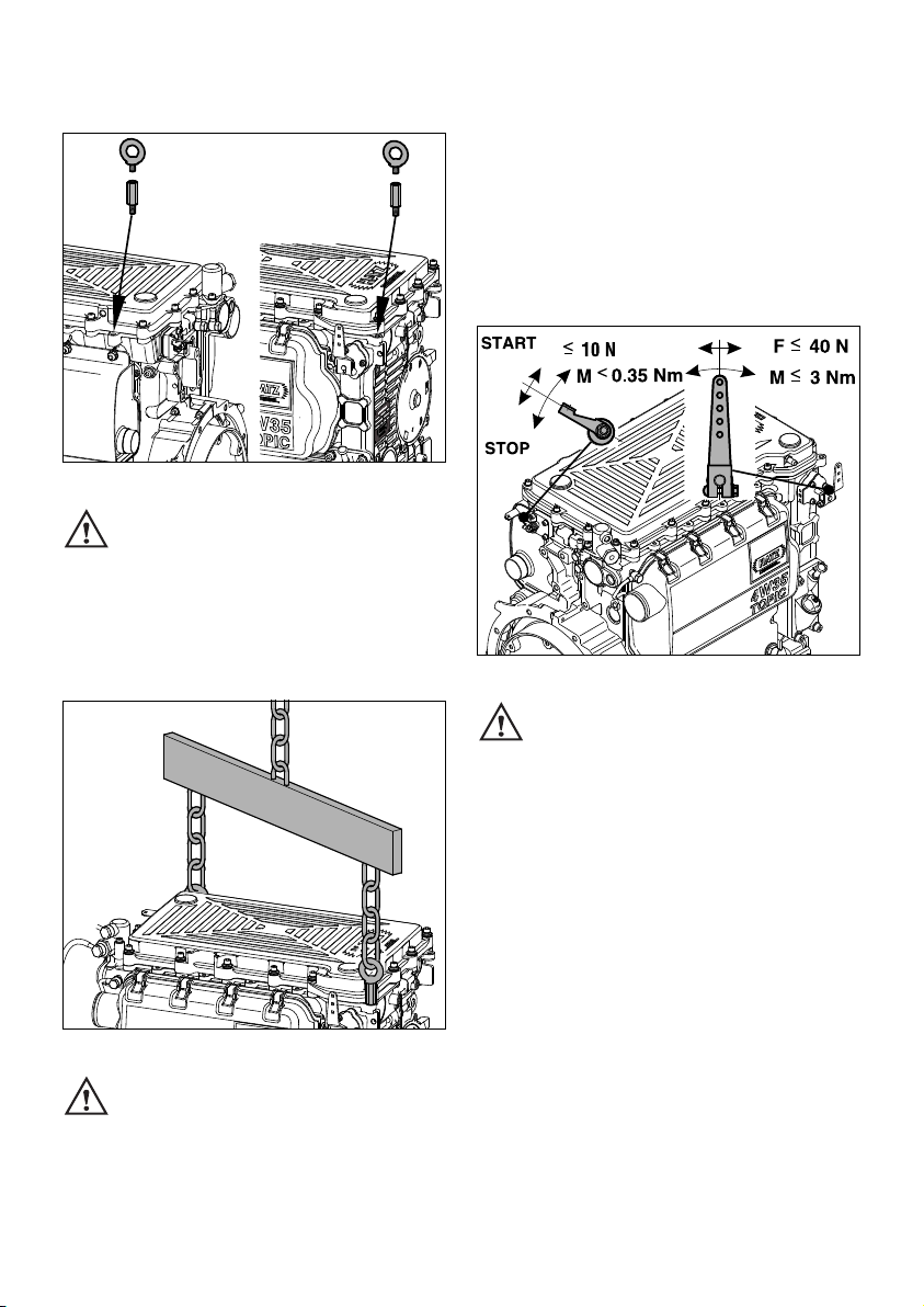
3.2. Transport
5
Watch out for the eyebolt securing
points.
The eyebolts are used to safely transport the
engine incl. the optional equipment.
They are not suited and not approved for
hoisting complete machines.
6
Make sure that only suitable hoisting
equipment with a sufficient lifting ca-
pacity is used for transport !
3.3. Instructions for installation
The „Manual for Selection and Installation of Engines“ contains all the information you need if
your engine has not yet been installed on or in
the equipment it is intended to drive, or set up in
its correct operating position. You can obtain a
copy of this manual from your nearest HATZ
service station.
7
The admissible forces and torques on
the speed adjusting lever and the stop
lever should be observed as exceeding them
can lead to damage to the stops and inner
governor parts.
3.4. Load on engine
See supplemental information for EPA certified
engines, Page 43; resp. supplemental information for California regulations for off road
engines, Page 57.
11
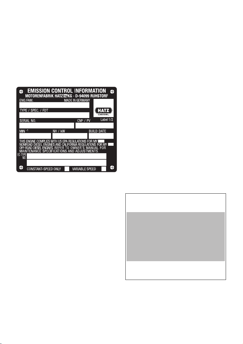
3.5. EPA/CARB-type plates and
fuel label
There are two EPA/CARB- type plates applied for
the identification of the engine. The type plates
are placed on the crankcase (chapt. 2).
They include the following emission control information (Figure 8a):
Label 1/2
8a
➀ EPA/CARB-Engine Family Number
➁ engine type / spec. (only for special
equipment) /Fuel Delivery Timing
➂ engine number
(also stamped on crankcase, Fig. 9)
➃ max. engine rated speed
➄ build date
➅ displacement
➆ rated power
➇ “constant speed only” (if requested)
➈ “variable speed” (if requested)
Every engine is equipped with an additional
loose engine type plate. If the original type
plate on the engine is not readily visible after
the engine is installed in the equipment then
the second loose type plate must be attached
on the equipment in such a manner that it is
readily visible to an average person.
For any offer as well as spare parts orders it is
necessary to mention the following data (also
see spare parts list, page 1):
➁ engine type / spec.
(only for special equipment)
➂ engine number
➃ max. engine rated speed
The layout is identical for constant-speed and
variable speed application.
Attention:
If the engine was certified for constant-speed
application and shall be used so, the field "constant-speed only" is marked with “X”.
If the engine was certified for variable speed application and shall be used so, the field "variable
speed" is marked with “X”.
Always install the engine for its intended application in order to comply with EPA and CARB
emission regulation requirements.
Label 2/2
8b
The engine must be operated with “LOW
SULFUR FUEL OR ULTRA LOW SULFUR FUEL
ONLY”.
The label also states the applicable emissionrelated power category of the engine.
12
➀
➁
➂
➃
➆
➇
➅
➄
➈
EMISSION CONTROL INFORMATION
LOW SULFUR FUEL OR
ULTRA LOW SULFUR FUEL ONLY
❏ < 8 kW / ❏ 8-19kW / ❏ 19-37kW /
❏ 37-56 kW PM Standard: 0.3 g/kWh
Power category:
Label 2/2
Fuel label
8c
The fuel label is placed nearby the fuel inlet.
If there was no fuel tank mounted to the engine,
the label has to be permanently attached to the
equipment near the fuel inlet.
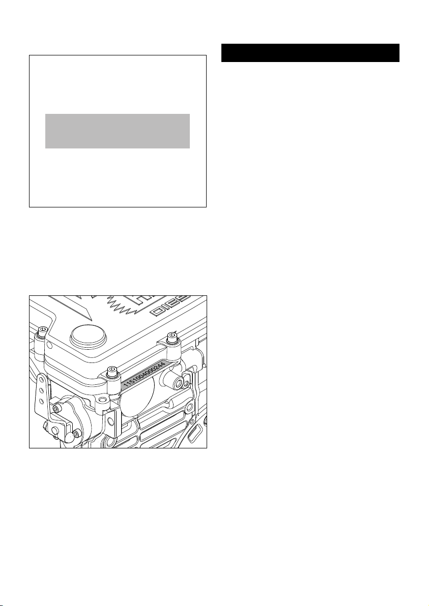
9
Engine serial number stamped on crankcase.
3.6. EMISSION-RELATED
INSTALLATION INSTRUCTIONS
See supplemental information for EPA certified
engines, Page 43; resp. supplemental information for California regulations for off road
engines, Page 57.
4. Operation
4.1. Before initial start-up
The engines are normally delivered to the customers without fuel, oil and coolant filling !
Important !
When replenishing liquids, it is essential
that any danger of confusion be excluded, as
mixing up liquids may cause serious damage
to the engine.
4.1.1. Engine oil
Oil quality
All premium oils which meet at least one of the
following specifications are suitable:
for naturally-aspirated engines
ACEA – B2 / E2 or superior
API – CF / CF-4 / CG-4 or superior.
for turbo engines
ACEA – B3 / E2 or superior
API – CF / CF-4 / CG-4 or superior
If engine oil of a poorer quality is used, reduce
oil change intervals to 150 operating hours.
13
LOW SULFUR FUEL OR ULTRA
LOW SULFUR FUEL ONLY
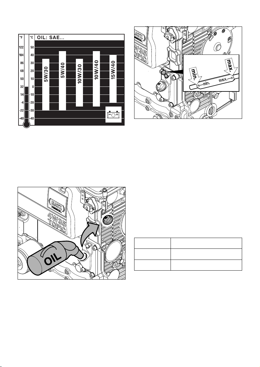
Oil viscosity
10
Choose a viscosity according to the ambient
temperatures where the engine is to be started
from cold.
The engine must be in a horizontal position before adding oil or checking the oil level.
11
– Remove oil drain plug and pour in engine oil.
For the quantity of lubricant required, refer to
Chapter 3.1.
12
– For oil level inspection, remove the dipstick
and wipe it dry using a lint-free, clean piece of
cloth; then insert it to its stop and pull it out
again.
– Read the oil level on the dipstick; if necessary,
add oil until the level reaches the max. mark.
Attention !
If the engine is operated while the oil level is below the min. mark, it will be damaged.
4.1.2. Coolant
The following radiator protection fluids have
been authorized by HATZ:
These radiator protection fluids provide efficient protection against corrosion, especially
in the case of aluminium engines, and against
freezing. Moreover, the coolant's boiling point is
essentially increased and limescale is prevented
from forming in the cooling system.
Manufacturer Product description
BASF Glysantin®G 30
TOTAL Glacelf Plus
14

Important !
The use of other products is only admissible
subject to previous consultation with the
factory.
Properties of the radiator protection fluids:
Important !
Mixing of the above-mentioned products is
admissible, however, the specifications of the
lower-grade product shall apply in this case.
A replacement interval of 2 years must be
complied with.
In the cooling system, mixed radiator protection fluids are characterized by their brown
colour.
Glysantin
®
G 30 and Glacelf Plus are available
from every HATZ Service station.
Product Properties
Glysantin
®
G 30
nitrite-, amine-, phosphateand silicate-free.
Identification colour: violet
Replacement interval: every
4 years
Glacelf Plus
nitrite-, amine- and phosphate-free. Contains silicate.
Identification colour: blue-
green
Replacement interval: every
2 years
Processing the coolant
Radiator protection fluids are detri-
mental to health. Thus, they may only
be stored in closed original containers and in a
place inaccessible to non-authorized persons.
Eye and skin contact must be avoided.
Comply with the manufacturer’s instructions.
– Add water to the coolant before pouring it in
the cooling circulation.
Clean water which is not excessively hard
must be used for processing. Tap water which
contains as little salts, minerals and suspended matter as possible is well suited.
The mixing ratio of the coolant should not fall
below or exceed the following concentration:
An insufficient concentration of coolant increases the risk of corrosion in the cooling system, as
well as the risk of freezing, depending on the
prevailing climate conditions.
If the portion of radiator protection fluid exceeds
50 percent by volume, this will impair the cooling effect as well as the anti-freeze protection.
Thus, if the concentration of the radiator protection fluid falls below or exceeds the specified
values, this may cause serious damage to the
engine.
Should you have any questions about the ideal
mixing ratio at your place of engine operation,
please do not hesitate to contact your HATZ
service station.
Radiator
protection
fluid
Water
Frost-
resistant
down to
approx.
min. 35 percent by
volume
65 percent by
volume
-22 °C
max. 50 percent by
volume
50 percent by
volume
-40 °C
15
Note:
As the concentration of the corrosion- and antifreeze protection fluid deteriorates long-term, it
must be checked yearly using a commercial antifreeze tester. If the concentration is too low, no
matter at which service interval, the coolant
must be replaced as described in Chapter 5.6.1.
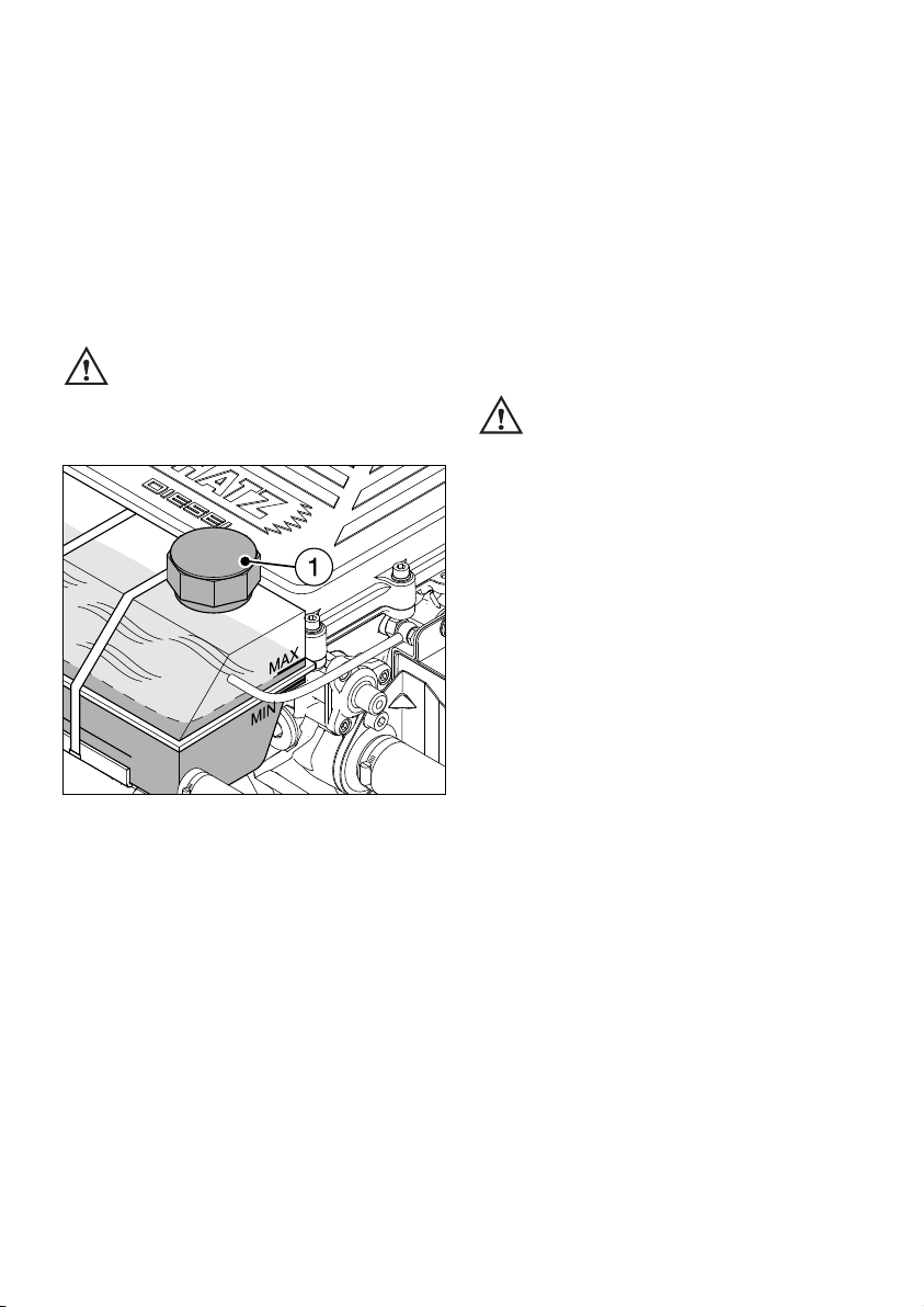
Filling the cooling system
Work on the cooling system must
not be performed while the engine
is warm - risk of scalding !
The cooling system is pressurized.
13
– Open cap 1.
– Pour in coolant until the level reaches the MAX
mark on the expansion tank.
– Tighten cap 1 by hand.
– After the engine has warmed up, check coolant
level again. When the engine is at a standstill
and has cooled down, the coolant level must
be visible between the tank’s MIN and MAX
marks; if the engine is warm, the level may be
slightly above the MAX mark.
– Check cooling system for leakage; if
necessary, re-tighten hose clamps.
Add coolant
While the engine is warm, the cap of
the expansion tank must not be opened
Risk of scalding. The cooling system is pressurized.
– First stop the engine and allow it to cool down.
Then put a piece of cloth over cap 1 of the expansion tank and open cap carefully (Fig. 13).
– Add coolant until the level is between the MIN
and the MAX mark (Fig. 13).
– Tighten cap 1 by hand.
16
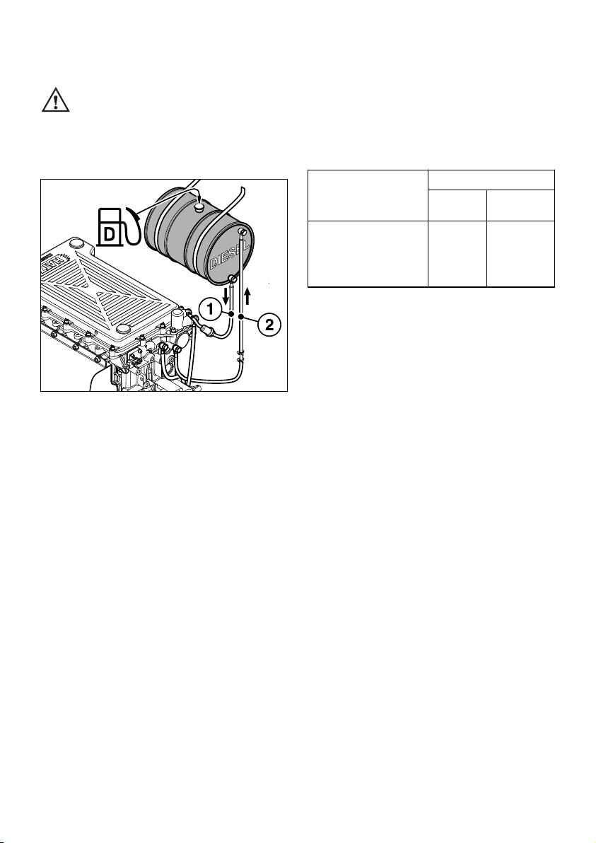
4.1.3. Fuel
Only refuel when engine is stopped.
Never refuel close to open flames or
flammable sparks, don’t smoke. Use only pure
fuel and clean replenishing vessels. Don’t spill
the fuel.
14
Pos. 1 = Fuel feed line
Pos. 2 = Fuel return line
All diesel fuels sold as fuel and complying with
the following minimum specification can be
used:
EN 590 or
BS 2869 A1 / A2 or
ASTM D 975 - 1D / 2D
Low temperature resistance
At low temperatures, the viscosity of Diesel fuel
increases. This may result in clogging of the fuel
system. Thus, winter fuel must be used at outside temperatures below 0 °C, or petroleum
must be added in time.
Bleeding the injection system
Air may enter into the injection system if the fuel
tank is completely emptied or while the primary
fuel filter or the fuel filter are replaced.
To bleed the system, proceed as described below, depending on whether the fuel tank is
arranged in HIGH position above the fuel supply
pump, or in LOW position below the fuel supply
pump:
Fuel tank HIGH
– Fill fuel tank completely with diesel fuel.
– Start the engine as described in Chapter 4.2.
Note:
The fuel system is bled automatically when the
engine is started. To this effect, starting may
take longer than usual.
To save the starter and the battery, do not
actuate the starter continuously for more than
15 to 20 seconds at a time. Make pauses of
approx. 1 minute between the various starting
attempts. Should the engine fail to start even at
the 2
nd
attempt, locate and eliminate the trouble
(Chapter 6).
Lowest ambient
temperature when
starting, in °C
Paraffin content for:
Summer
fuel
Winter
fuel
0
up to
–10
–10
up to
–15
–15
up to
–20
–20
up to
–30
20 %
30 %
50 %
–
–
–
20 %
50 %
17

Fuel tank LOW
If the fuel tank is located at an even lower level,
a manual fuel pump or an electrical supply pump
must be used for bleeding.
Models with manual fuel pump
15
– Place a suitable vessel under the filter to trap
escaping fuel.
– Open the vent screw 1 by approx. one turn.
16
– Compress and release rubber ball repeatedly,
until fuel escapes from the vent screw 1.
– Close vent screw 1, then actuate rubber ball
another two times.
1
– Start the engine as described in Chapter 4.2.
Models with electrical supply pump
– With this model, first turn the starter key to
position I and wait for approx. one minute,
Chapter 4.2.2. During this waiting time, the
fuel system is largely bled by means of the
electrical supply pump.
– Start the engine as described in Chapter 4.2.
4.2. Starting the engine
Do not run the engine in closed or in-
sufficiently ventilated rooms – danger
of poisoning ! Before the engine is started, always make sure that nobody is in the danger
area (moving parts on engine or machinery)
and that all safety guards are in place.
17
Never use any spray starting aids.
050 145 00
18
4.2.1. Preparations for starting
– If possible, disengage the engine from any
driven equipment. The auxiliary equipment
should always be placed in neutral.
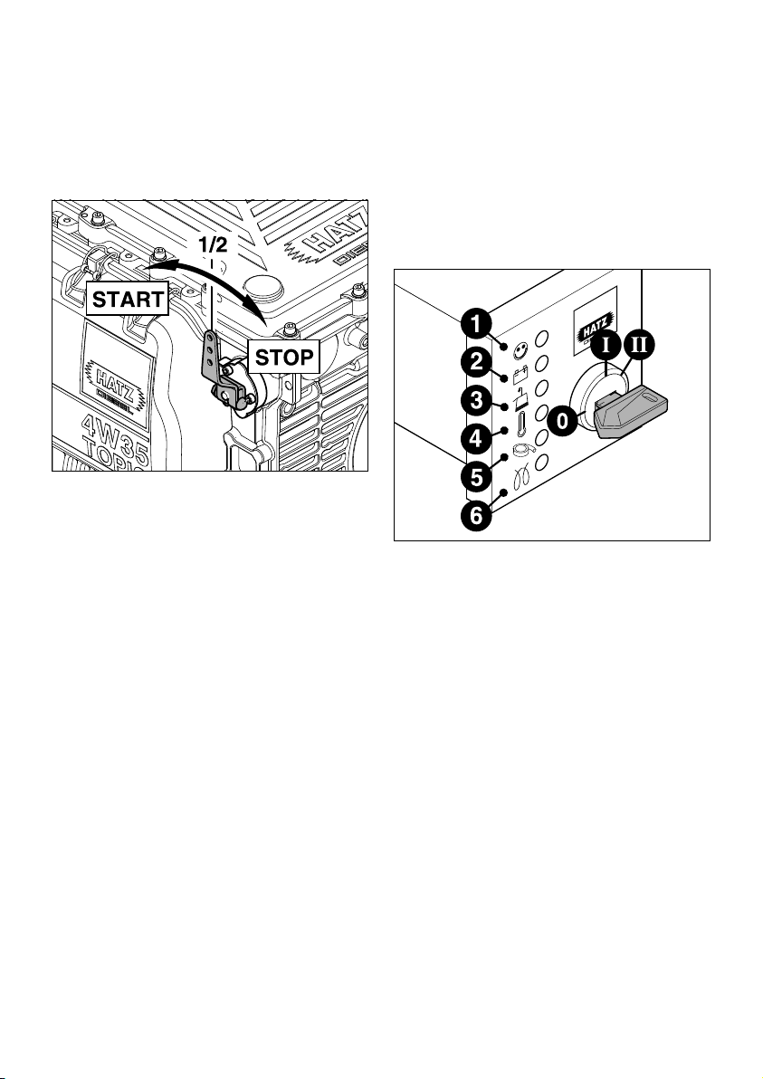
18
– Set speed control lever to a position between
1/2 START and max. START, according to requirements. Selecting a lower engine speed
will reduce smoke when starting.
4.2.2. Electric starter
To save the starter and the battery, do not
actuate the starter continuously for more than
15 to 20 seconds at a time. Make pauses of
approx. 1 minute between the various starting
attempts. Should the engine fail to start even at
the 2
nd
attempt, locate and eliminate the trouble
(Chapter 6).
19
– Insert the key to its stop and turn it to
position I.
– Battery charge pilot lamp 2 and oil pressure
warning 3 must light up.
– Turn starter key to position II.
– As soon as the engine runs, release the starter
key. It must return to position I by itself and
remain in this position during operation.
The battery charge pilot lamp and oil pressure
warning must go out immediately after starting. Indicator light 1 is on when the engine is
in operation, Fig. 19.
– The air cleaner maintenance indicator 5 only
goes on during operation to show that the air
cleaner needs cleaning or replacement
(Fig. 19, Chapter 5.4.3).
19

– The engine temperature indicator 4 goes on as
soon as the coolant becomes inadmissibly hot.
Stop the engine immediately and trace and
eliminate the cause of the problem, Chap. 6.
– Always turn the starter key back to position 0
before re-starting the engine. The repeat lock
in the ignition lock prevents the starter motor
from engaging and possibly being damaged
while the engine is still running.
Important !
If a start protection module is installed, the
starter key has to be returned to position 0 for
at least 8 seconds if the engine has failed to
start before a further attempt to start the engine
can be made.
Preheating device with automatic
heating timer
(optional equipment)
The preheating light 6 lights up additionally at
temperatures below 0° centigrade (Fig. 19).
– After the light has gone out, start the engine
without delay.
Automatic electrical shutdown system
(optional equipment)
This is characterized by a brief flashing of all
pilot lamps once the starter key has been turned
to position I, figure 19.
Important !
If the engine cuts out immediately after starting
or switches off by itself during operation, a
monitoring element in the automatic shutdown
system has tripped. The corresponding indicator
light (Fig. 19, positions 2 - 4) will come on.
After the engine has stopped, the indicator remains lit for another approx. 2 minutes.
The electrical device then switches off
automatically.
The display lights up again after the starter key
has been turned back to position 0, and then to
position I again.
Trace and eliminate the cause of the operating
fault before trying to restart the engine
(see Chapter 6).
The indicator light goes out when the engine is
next started.
Even with automatic shutdown monitoring
the oil level must be checked every 8 – 15
operating hours (Chapter 5.2.1. and 5.2.5.).
20
 Loading...