

Page 1
2G40
2G40 H
33
0000 433 302 06 - ENG - 01.11 - 0.2
Printed in Germany
Translation of the
ORIGINAL INSTRUCTION BOOK
Page 2
A new HATZ Diesel engine - working for you
This engine is intended only for the purpose determined and tested by the manufacturer of the
equipment in which it is installed. Using it in any other manner contravenes the intended purpose.
For danger and damage due to this, Motorenfabrik HATZ assumes no liability. The risk is with the
user only.
Use of this engine in the intended manner presupposes compliance with the maintenance and repair
instructions laid down for it. Noncompliance leads to engine breakdown.
Please do not fail to read this operating manual before starting the engine. This will help you to avoid
accidents, ensure that you operate the engine correctly and assist you in complying with the maintenance intervals in order to ensure long-lasting, reliable performance.
Please pass this Instruction Manual on to the next user or to the following engine owner.
Always have service work performed by qualified specialists. To this effect, we recommend that you
consult one of the 500 HATZ service stations. There, your engine is repaired by staff who constantly
undergo training and who use both original HATZ spare parts and HATZ tools. The world-wide HATZ
service network is also available to you for consultation and spare parts supply.
For the address of your nearest HATZ service station, please refer to the attached list or the internet
under: www.hatz-diesel.com
The installation of inappropriate spare parts may cause problems. We cannnot accept any liability for
damage or consequential damage resulting therefrom.
Thus, we recommend that you use original HATZ spare parts. These parts are manufactured following the strict HATZ specifications and ensure, thanks to their perfect fit and function, maximum operating reliability. For the reference number, please consult the attached spare part list or the internet
under: www.hatz-diesel.com. Please take the complete spare parts kits in Table M00 into account.
We reserve the right to make modifications in the course of technical progress.
MOTORENFABRIK HATZ GMBH & CO KG
1
Page 3

2
Page
1. Important notes on safe operation
of the engine 3
2. Description of the engine 5
3. General information 6
3.1. Technical data 6
3.2. Transport 7
3.3 Instructions for installation 7
3.4. Load on engine 7
3.5. Type plate 8
4. Operation 8
4.1. Before initial start-up 8
4.1.1. Engine oil 8
4.1.2. Oilbath air cleaner 9
4.1.3. Fuel 10
4.2. Starting the engine 11
4.2.1. Preparations for starting 11
4.2.2. Electric starter 11
4.3. Stopping the engine 13
5. Maintenance 14
5.1. Maintenace summary 14
5.2. Maintenance every 8 – 15
hours of operation 16
5.2.1. Check engine oil level 16
5.2.2. Check combustion air intake area 16
5.2.3. Check the cooling air system 17
Page
5.3. Maintenance every 250
hours of operation 18
5.3.1. Maintenance work on oilbath
air cleaner 18
5.3.2. Engine oil change and
oil filter renewal 18
5.3.3. Check and adjust vlave clearances 20
5.3.4. Clean the cooling air system 21
5.3.5. Check threaded connections 22
5.4. Maintenance every 500
hours of operation 22
5.4.1. Renew the fuel filter 22
5.4.2. Dry-type air cleaner maintenance 23
6. Functional test 24
6.1. Air filter maintenance indicators 24
7. Malfunctions – Causes – Remedies 25
8. Work on the electrical system 29
9 . Protective treatment 29
Declaration for Incorporation 30
Contents
This symbol identifies important safety precautions.
Please comply with these most carefully in order to avoid any risk of injury to persons or
damage to materials.
General legal requirements and safety regulations issued by the competent authorities or
industrial accident insurers must also be complied with.
Page 4

1. Important notes on safe operation of the engine
HATZ diesel engines are economical, stronly built and long-lasting. They are therefore frequently
chosen for commercially and industrially operated equipment and machinery.
Since the engine forms part of the finished equipment or machine, its manufacturer will take all the
applicable safety regulations into account.
Nevertheless, we give below certain additional comments on operating safety, and would recommend
you to note them carefully.
Depend on the manner in which the engine is installed and its intended application, the equipment
manufacturer or operator may have to attach additional safety devices and prohibit potentially
hazardous aspects of operation, for example:
– Exhaust system components as well as the surface of the engine will naturally be hot and must not
be touched while the engine is running or until it has cooled down after being stopped.
– Faulty wiring or incorrect operation of electrical equipment may lead to sparks forming, and must
be avoided as a potential fire hazard.
– Rotating parts must be shielded against accidental contact when the engine is installed in other
equipment or machinery.
Guards are available from HATZ to protect belt drives to cooling fans and generators.
– Before attempting to start the engine it is essential to have studied the starting information in the
instruction book.
– Mechanical starting devices must not be used by children or persons of insufficient physical
strength.
– Before starting the engine, ensure that all the specified protective guards are in place.
– The engine must only be operated, serviced or repaired by persons who have received the
appropriate trainig.
– Keep the ignition key out of reach of unauthorized persons.
– Do not run the engine in closed or badly ventilated rooms.
Do not breath in emissions – danger of poisoning!
– Also fuel and lubricants could contain poisonous components. Please follow the instructions of the
mineral oil producer (safety data sheets).
3
Page 5

Important notes on safe operation of the engine
– Stop the engine before performing any maintenance, cleaning- or repair work.
– Stop the engine before refuelling.
Never add fuel near a naked flame or a source of sparks.
Don't smoke. Don't spill fuel.
– Keep explosive materials as well as flammable materials away from the engine because the exhaust
gets very hot during operation.
– Wear close-fitting clothing when working on a running engine.
Please don't wear necklaces, bracelets or any other things which you could get caught with.
– Please pay attention to all advice- and warning stickers placed on the engine and keep them in legi-
ble condition. In case a label has come off or is no longer clearly legible, it must be replaced immediately. To this effect, please contact the HATZ service station in your area.
– Note that any unauthorized modification to the engine absolves its manufacturer from liability for
the consequences.
Regular servicing in accordance with the details provided in this instruction book is essential to keep
the engine operating reliably.
In case of doubt, always consult your nearest HATZ service station before starting the engine.
4
Page 6
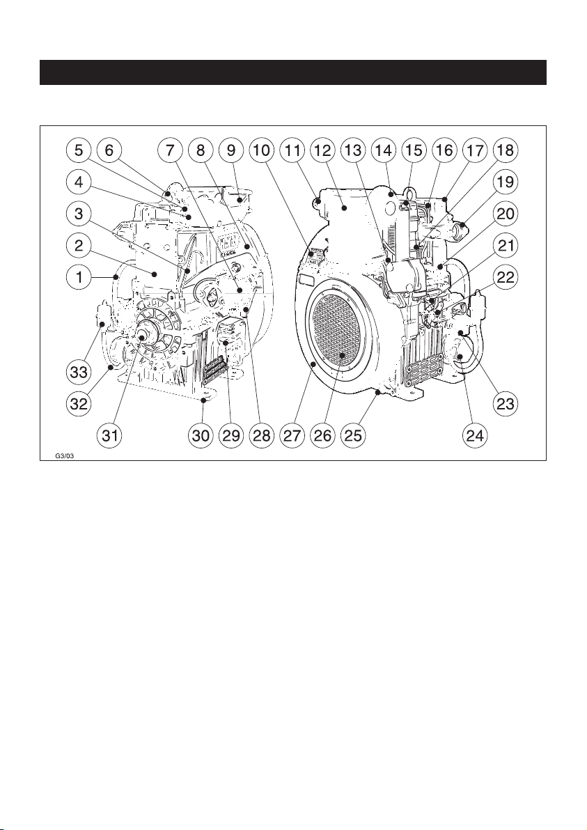
2. Description of the engine
5
Fig. 1
1 Fuel line (feed pump –
fuel-injection pump)
2 Air deflector
3 Oil dipstick
4 Fuel return line
5 Injector
6 Lifting eyebolt
7 Starter motor
8 Air guide
9 Air intake pipe
10 Type plate
11 Glow plug
(additional equipment)
12 Oilbath air cleaner
13 Oil pressure switch
14 Rainproof cap
15 Oil filler cap
16 Fuel pressure pipe
17 Cylinder head cover
18 Engine oil line
19 Exhaust manifold
20 Fuel injection pump
21 Stop lever
22 Speed control lever
23 Fuel feed pump
24 Engine oil filter
25 Oil drain plug
26 Guard
27 Air guide housing
28 Separable connector
29 Voltage regulator
30 Engine mount
31 Crankshaft, power-take-off
32 Fuel line
(fuel filter - feed pump
33 Fuel filter
Page 7

3. General remarks
3.1. Technical data
Type 2G40 / 2G40H
Design Air-cooled four-stroke diesel engine
Combustion system Direct injection
Number of cylinders 2
Bore/stroke mm 92 / 75
Displacement cm³ 997
Engine oil content 2.5 excl. sump
1)
incl. filter renewal l. approx. 3.0 incl. sump
1)
Difference between
„max“ and „min“ levels l. approx. 0.8
1)
Engine oil pressure min. 1 bar at 900 r.p.m. engine speed
Engine oil consumption
(after running-in period) approx. 1% of fuel consumption at full load
Direction of rotation,
power take-off end anti-clockwise
Valve clearances at 10 - 30 °C
Inlet/exhaust mm 0.10
Max. permissible perm. inclination Exhaust Flywheel
Angle of inclination in ° low high low high
without oil sump 30
2)
17
2)
25
2)
25
2)
with oil sump 30 2)17
2)
30
2)
25
2)
Weight (incl. fuel tank, air-cleaner, kg
exhaust silencer and electric starter) approx. 106
Battery capacity min / max 12 V - 45 / 88 Ah • 24 V - 36 / 55 Ah
1)
These values are intended as an approximate guide. The max. marking on the dipstick is the
determining factor, Fig. 6.
2)
Exceeding these limits causes engine breakdown.
6
Page 8
3.2. Transport
2
The lifting eyebolt provided as stand-
ard equipment is intended for safe
movement of the engine.
It is not intended for lifting complete machinery to which the engine is attached, and this is
strictly forbidden.
3.3. Instructions for installation
If you have an engine which is not yet installed
in a machine and still has to be installed, make
sure that the Assembly Instructions for HATZ
Diesel Engines are complied with prior to installation. These Assembly Instructions contain important information about safe assembly of the
engine and are available from your the HATZ
service center in your area.
Pending complete installation, the engine
must not be started !
Moreover, we would like to point out that in this
case, commissioning of the machine is also prohibited until it has been verified that the machine
into which this engine is to be incorporated
complies with all the safety precautions and regulations provided by law.
Refer also to the Declaration for Incorporation
at the end of these Operating Instructions.
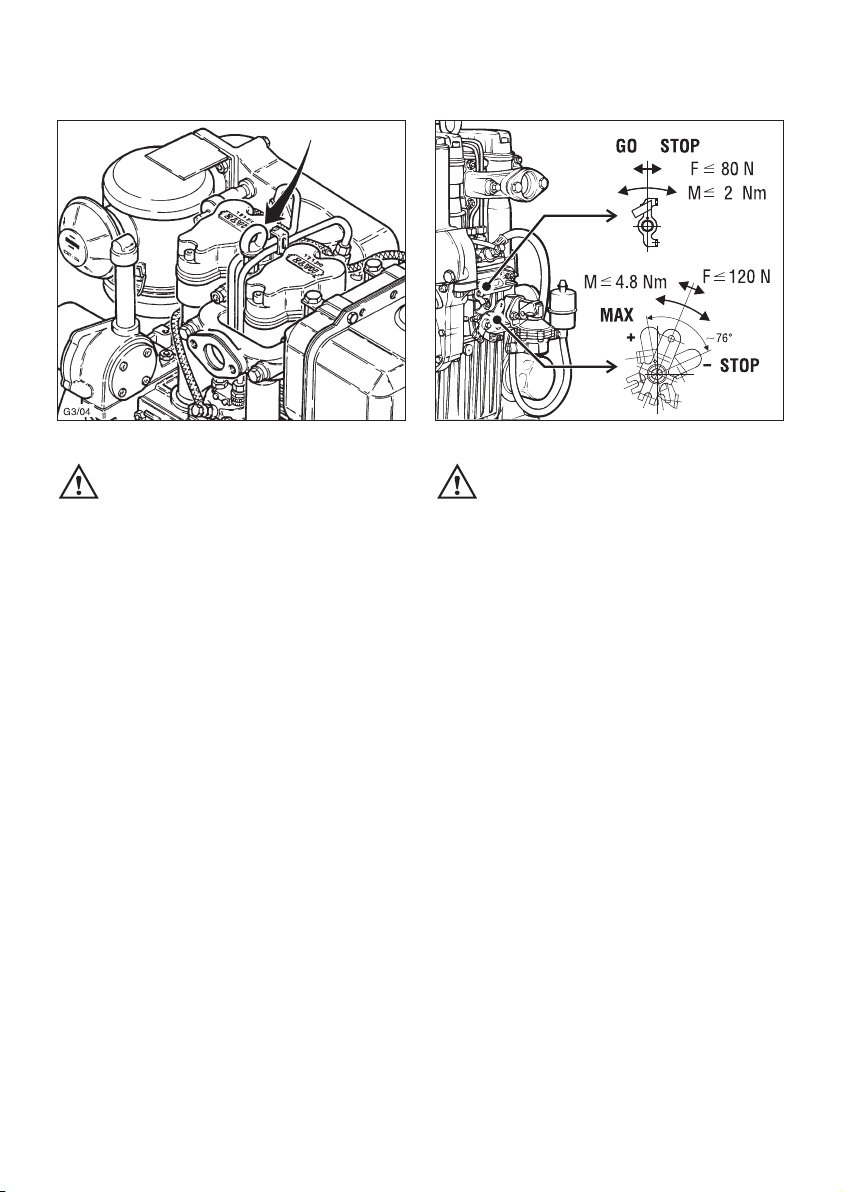
3
The permitted loads and elements on
the speed adjusting lever and the stop
lever should be observed as an exess can lead
to damage to the contacts and inner governor
parts.
3.4. Load on engine
Operating the engine for a lengthy period offload or at very low loads can affect its running
quality.
We therefore recommend a minimum engine
load of 15 %. If operated at such low loads, it is
best to operate the engine at a significantly higher load for a short period before switching it off.
7
Page 9
8
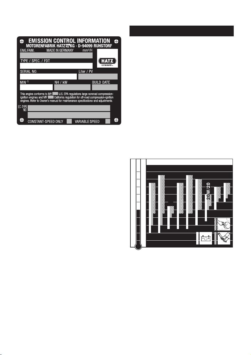
3.5. Type plate
4
The type plate is placed on the air guide (Fig. 1,
pos. 10) and includes the following engine information:
➀ engine type
➁ code (only for special equipment)
➂ engine number
➃ max. engine speed
For any offer as well as spare parts orders it is
necessary to mention these data (also see spare
parts list, page 1).
➀
➁
➂
➃
4. Operation
4.1. Before initial start-up
Engines are normally delivered without fuel and
oil.
4.1.1. Engine oil
Oil quality
Qualified are all trademark oils which fulfil at
least one of the following specifications:
ACEA – B2 / E2 or more significant
API – CD / CE / CF / CF-4 / CG-4 or more
significant.
If engine oil of a poorer quality is used, reduce
oil change intervals to 150 hours of operation.
Oil viscosity
5
Please select the recommended viscosity depending on the ambient temperature at which
the engine is operated.
Inappropriate engine oil may shorten the
engine’s service life significantly.
-40
-30
-20
-10
0
10
20
30
40
50
104
86
68
50
32
14
-4
-22
-40
OIL: SAE...
°C°F
5W/30
5W/40
10W/40
10W/30
15W/40
30
40
122
10 W
Page 10
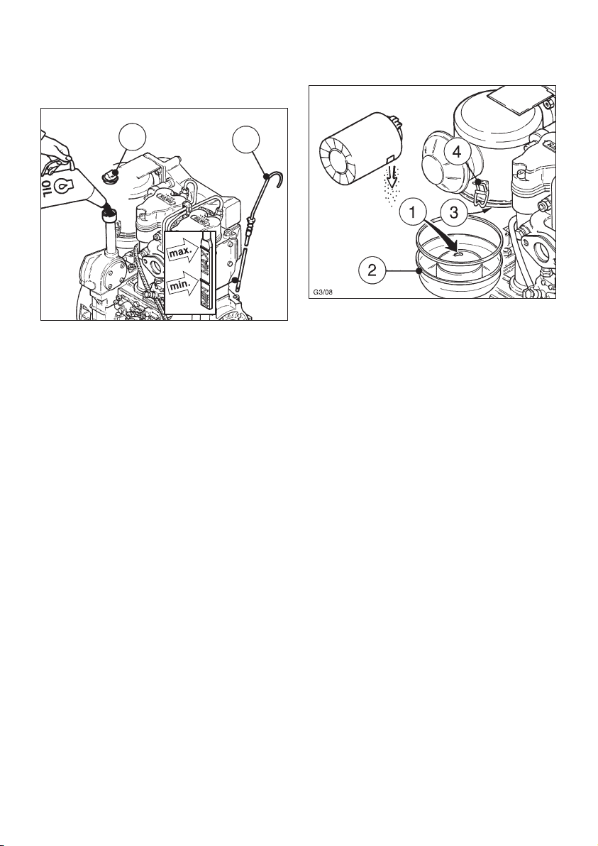
When adding oil or checking the level, the engine must be in a horizontal position.
6
– Remove oil filler screw „1“ and dipstick „2“.
– Add engine oil up to the max. mark on the
dipstick.
Lubricating oil capacity: see Chapter 3.1.
– Insert the oil filler screw and tighten it (hand-
tight only).
Attention !
If the engine is operated while the oil level is
below the min. mark or above the max. mark,
it can cause damage to the engine.
1
2
4.1.2. Oilbath air cleaner
7
If a cyclone-type dust trap is fitted, make sure
that the dust outlet is pointing in the correct
direction.
– Fill the oil tank up to mark „1“ with engine oil.
– Attach oil tank „2“, making sure that sealing
ring „3“ is correctly seated and clips „4“ are
fastened securely.
9
Page 11

4.1.3. Fuel
8
Stop the engine before refuelling.
Never add fuel near a naked flame or
a source of sparks. Don't smoke. Use only pure
fuel and clean filling equipment. Take care not
to spill fuel.
Diesel fuel complying with the minimum requirements of the following specifications may be
used:
EN 590 or
BS 2869 A1 / A2 or
ASTM D 975 - 1D/2D
Important !
The use of fuels of different specifications
requires the prior written consent of the HATZ
headquarters.
9
Before starting for the first time or if the fuel
system was run dry, prime it by operating lever
„1“ on feed pump „2“ until fuel is heard to flow
back into the fuel tank through the return line.
At temperatures below 0 °C, winter-grade fuel
should be used or paraffin added to the fuel well
in advance.
Lowest ambient
temperature when
starting, in °C
Paraffin content for:
Summer Winter
fuel fuel
0 up to –10 20 % –
–10 up to –15 30 % –
–15 up to –20 50 % 20 %
–20 up to –30 – 50 %
10
Page 12

4.2. Starting the engine
Do not run the engine in closed or
badly ventilated rooms – danger of
poisoning!
Before starting the engine, make sure that no
one is within the danger area near the engine
or the machinery it is driving, and that all the
necessary guards are installed.
4.2.1. Preparations for starting
– If possible, disengage the engine from any
driven equipment
The auxiliary equipment should always be
placed in neutral.
10
– Depending on operation conditions and re-
quirements, set speed control lever „1“ to either the 1/2 START or max. START position.
– Make sure that stop lever „2“ is in the off
position „START“.
Start
Run
Stop
Start
Stop
11
Never use starting aids in the form of
aerosols or sprays !
4.2.2. Electric starter
– For starting preparations, see Chapter 4.2.1.
12
– Insert the start key to its stop and turn it to
position I.
Battery charge telltale „2“ and oil pressure
warning light „3“ will come on.
– Turn start key to position II
11
Page 13

– As soon as the engine runs, release the start
key. It must return to position I by itself and
remain in this position during operation.
The battery charge telltale and oil pressure
warning must go out immediately after starting. Indicator light „1“ is on when the engine
is in operation.
– The engine temperature display „4“ (additional
equipment) lights up if the temperature at the
cylinder head becomes too high.
Switch off the engine and trace and eliminate the cause of the problem, chapter 7.
– The air cleaner maintenance indicator „5“
(additional equipment) only lights up during
operation if the air cleaner element needs to
be cleaned or renewed (chapter 5.4.2.).
– Always turn the start key back to position 0
before re-starting the engine. The repeat lock
in the ignition lock prevents the starter motor
from engaging and possibly being damaged
while the engine is still running.
Important !
If a starter protection module is fitted, the key
must be turned back to position 0 for at least
8 seconds if the engine fails to start, before a
second attempt of starting can be made.
Note:
Start for max. 30 seconds. If the engine does
not run after this time, turn starter key back to
position 0 and eliminate the cause, Chapter 7.
Preheating device with automatic heating
timer (additional equipment)
The preheating light „6“ lights up additionally at
temperatures below 0° Celsius (Fig. 12).
– After the light has gone out, start the engine
without delay.
Automatic shut-down function
(additional equipment)
This is characterized by a brief flashing of all
pilot lamps once the starter key has been turned
to position I (Fig. 12).
Important !
If the engine cuts out immediately after starting
or switches off by itself during operation, a monitoring element in the automatic shutdown system has tripped. The corresponding indicator
light (Fig. 12, positions 2 - 4) will come on. After
the engine has stopped, the display continues to
glow for about 2 minutes.
The electrical device then switches itself off automatically.
The display lights up again after the start key
has been turned back to position 0 and then to
position I again.
Trace and eliminate the cause of the
operating fault before trying to restart the
engine (see chapter 7).
The display light goes out when the engine is
next started.
Even with automatic shutdown monitoring the
oil level must be checked every 8 – 15 operating hours (chapter 5.2.1.).
12
Page 14

4.3. Stopping the engine
13
– Move speed control lever „1“ back to the
„STOP“ position.
– On engines with the lower idling speed out of
use, move speed control lever „1“ back, then
move stop lever „2“ towards STOP and hold it
there until the engine has come to a standstill.
– Once the engine is not running any longer,
release the stop lever. The stop lever is returned automatically to its operating position
START via a spring.
Start
Run
Stop
Start
Stop
14
– The battery charge telltale light „2“ and the oil
pressure warning light „3“ come on.
– Turn the starter key back to position „0“ and
pull it out. The telltale and warning lights must
go out.
Note:
Engines with an automatic electrical shutdown
system can also be stopped by turning the
starter key back to positon „0“.
During breaks in operation or at the
end of the work session, pull out the
starter key and keep in a safe place where it
cannot be reached by unauthorized persons.
3
2
13
Page 15

14
5. Maintenance
5.1. Maintenance summary
Maintenance interval Maintenance work required Chap.
The engine must be stopped before any maintenace work is attempted.
Comply with legal requirements when handling and disposing of old oil, filters and
cleaning materials.
Keep the engine's starting key and starting handle out of reach of unauthorized persons.
To immobilize engines with an electric starter, disconnect the negative battery terminal.
At the end of the maintnance work, check that all tools have been removed from the engine and
all safety guards, covers etc. replaced in their correct positions.
Before starting the engine, make sure that no-one is in the danger area (engine or driven
machinery).
Every 8 – 15
operating hours or
before daily starting
Check oil level.
Check area around combustion air input.
Check cooling air system.
Check that the oil level in the lower part of the
oil bath air cleaner is correct and that the oil is
not contaminated.
5.2.1.
5.2.2.
5.2.3.
4.1.2.
5.3.1.
Every 250
operating hours
Maintenance of air filter/oil bath air filter.
Replace engine oil and oil filter.
Check and adjust valve clearances.
Clean cooling air system.
Examine screw connections.
5.3.1.
5.3.2.
5.3.3.
5.3.4.
5.3.5.
Every 500
operation hours
Renew fuel filter.
Maintenance of air filter/dry-air filter
5.4.1.
5.4.2.
250
500
8-15
Page 16

The above maintenance chart is supplied with
every engine. This label should be affixed to the
engine or equipment in an easily visible position.
The maintenance chart governs the maintenance
intervals.
For new or reconditioned engines, the following
must always be carried out after the first 25
operating hours.
– Replace engine oil and oil filter, chap. 5.3.2.
– Check tappet clearance, and adjust if necess-
ary, chap. 5.3.3.
– Examine screw connections, chap. 5.3.5.
For short operating periods: replace engine oil
and oil filter after 12 months at the latest,
regardless of the number of operating hours.
15
Page 17

5.2. Maintenance work every 8 – 15
operating hours
5.2.1. Check engine oil level
When the oil level is checked, the engine must
be stopped and in a horizontal position.
– Remove any dirt in the dipstick area.
15
– For oil level inspection, remove the dipstick „2“
and wipe it dry using a lint-free, clean piece of
cloth; then insert it to its stop and pull it out
again.
– Check oil level at the dipstick; top up if
necessary as far as the „max“ mark (see
Chapter 4.1.1.).
Attention !
If the engine is operated while the oil level is
below the min. mark or above the max. mark, it
can cause damage to the engine.
5.2.2. Check combustion air intake area
Heavy contamination is an indication that increased dust accumulation necessitates a correspondingly shorter maintenance interval,
Chapter 5.3.1. and 5.4.2.
1
2
With oilbath air cleaner:
16
– Inspect air inlets „1“ (depending on version)
for severe dirt and dust deposits, and clean if
necessary.
– Make sure that dust outlet „2“ on the
cyclone-type dust trap (depending on version)
is not obstructed, and clean if necessary
(chap. 5.3.1.).
With dry-type air cleaner:
17
– Inspect air inlets „1“ and clean if necessary.
– Check that dust discharge valve „2“ is not ob-
structed; eliminate dust blockage by pressing
together as shown.
16
Page 18

17
– Check that connecting hose „3“ and hose clips
„4“ are in good condition and not leaking
(fig. 17).
18
– Run the engine up to maximum speed briefly
and check that indicator lamp „1“ (depending
on version) comes on briefly or that the red
zone is visible in maintenance indicator „3“.
1
5.2.3. Check the cooling air system
Heavy contamination is an indication that increased dust accumulation necessitates acorrespondingly shorter maintenance interval.
19
– Inspect air inlets and outlets for coarse soiling
such as leaves, dust accumulation etc., clean if
necessary (chap. 5.3.4.).
The temperature indicator „1“ – if installed – will
light up as soon as the engine becomes
too hot.
Shut down the engine immediately !
Page 19

5.3. Maintenance work every 250
operating hours
5.3.1. Maintenance work on oilbath
air cleaner
20
Trap the old oil and dispose of it in
accordance with local legislation.
– Take off the oil tank „1“.
– Remove contaminated oil and sludge from the
oil tank, and clean it out.
– Take off rain cap „2“ or cyclone-type dust trap
„3“, and clean.
– Clean right through intake pipe „4“
– Check condition of sealing ring „5“ and renew
if necessary.
– Add engine oil to the oil tank up to mark „6“
and re-assemble the oilbath air cleaner
(fig. 20, chap. 4.1.2.).
If the filter packing is severely contaminated with
dust and dirt, the upper part of the air cleaner
must also be cleaned as follows:
21
– Detach upper part of air cleaner „1“ from
engine and rinse in diesel fuel.
– Allow the diesel fuel drip off thoroughly, or
wipe it off, before re-assembling.
– Install a new filter packing if the sealing sur-
face is uneven, the body of the filter is cracked
and/or filter wool is missing.
– Install the upper part of the air cleaner, using a
new flange gasket „3“.
– Re-assemble the remaining parts of the air
cleaner and fill with oil to prepare for further
operation (chap. 4.1.2.).
5.3.2. Engine oil change and
oil filter renewal
The engine must be stopped and in a horizontal
position.
Drain the engine oil only when the engine is
warm.
Danger of scalding from hot oil !
Trap the old oil and dispose of it in
accordance with local legislation.
2
1
3
18
Page 20

22
23
– Take out drain plug „1“ and allow the oil to
drain out completely (fig. 22 without oil sump,
fig. 23 with oil sump).
– Insert oil drain plug „1“ with a new sealing
ring „2“ and tighten.
24
– Slacken off and unscrew the throwaway engine
oil filter using HATZ strap wrench „1“, Order
No. 620 307 01, or a similar tool.
25
– Use a screwdriver to lift mesh screen „1“,
which is located behind the filter element,
away from the oil pressure relief valve.
Do not damage contact face „2“.
– Clean mesh screen „1“ from the inside by
blowing through with compressed air.
Persons handling compressed air must
wear protective goggles. Never direct
the jet to animals, persons or yourself !
1
G3/28
2
19
Page 21

– After cleaning, press the mesh screen back on
to the oil pressure relief valve.
26
– Clean sealing face „1“ thoroughly.
– Never re-use the throwaway filter element.
Oil sealing ring „2“ on the new filter element
lightly.
– Screw in throwaway filter element „3“
handtight.
– Add engine oil (chap. 4.1.1.).
– Run the engine briefly to check that there
are no leaks at the oil filter; take up slack if
necessary.
– Check the oil level; add oil if necessary
(chap. 5.2.1.).
5.3.3. Check and adjust vlave clearances
– Adjust only when the engine is cold
(10 - 30 °C).
– Remove any dirt from the area where the
cover is attached to the cylinder head.
27
– Remove screws „1“ and take off cover „3“
complete with sealing rings „2“ and „4“.
Never re-use these sealing rings.
Adjusting procedure:
– Cylinder 1 is at the flywheel end; clockwise
rotation.
Cylinder 2 is at the power take-off end; anticlockwise rotation.
– Turn the engine in its normal direction of rota-
tion until the valves in cylinder 2 are in the
overlap position (exhaust valve not yet closed,
inlet valve starts to open).
– Turn the crankshaft through 180 degrees in the
normal direction of rotation, then check valve
clearances for cylinder 1 and adjust if necessary.
– Turn the crankshaft through a further 180 de-
grees; check valve clearances for cylinder 2
and adjust if necessary.
20
Page 22

Adjusting:
– Measure valve clearance with 0.10 mm feeler
gauge „5“ (fig. 27, chapt. 3.1.).
– If adjustment is necessary, slacken off hex nut
„6“, turn adjusting screw „7“ and retighten nut
„6“. It should then be possible to pull feeler
gauge „5“ through with just perceptible resistance to movement (fig. 27).
– Replace the cover in position and tighten it
down uniformly.
– Run the engine briefly to check that there are
no leaks at the cover.
5.3.4. Clean the cooling air system
28
– Take off all air guides.
If dirt deposits are dry:
– Clean all air guides and the entire cooling air
system including cylinder heads, cylinders and
flywheel blades without making them wet, and
blow them through with compressed air.
Persons handling compressed air must
wear protective goggles. Never direct
the jet to animals, persons or yourself !
If dirt deposits are damp or oily:
– Disconnect the battery.
– Apply a detergent solution (cold cleaner or
similar) to the entire system in accordance
with the manufacturer's instructions, then
spray off with a powerful water jet.
Do not splash electrical device with water jet
or pressure jet during engine cleaning.
– Establish the cause of contamination with oil
and have any leaks repaired.
Re-attach all air guides.
The engine must never be run without
the air guides.
– Run the engine immediately after re-assembly
until it is warm; this will prevent rust from
forming.
21
Page 23

5.3.5. Check threaded connections
Check the condition and tightness of all threaded
connections, pipes and lines, hose clips and
other fastenings on the engine or its mountings
which can be reached during maintenance work.
Do not tighten the cylinder head bolts.
29
The adjusting screws at the engine
governor and on the injection system
are sealed with lacquer or with lead and are
not to be tightened or adjusted.
5.4. Maintenance work every 500
hours of operation
5.4.1. Renew the fuel filter
The maintenance intervals for the fuel filter are
dependent upon the purity of the diesel oil being
used and, if necessary, may have to be reduced
to 250 hours.
When working on the fuel system, do
not expose it to naked flames; do not
smoke.
Important !
Keep the entire area clean so that no dirt
reaches the fuel. Fuel particles may damage
the injection system.
– Shut off the fuel supply.
30
– Pull fuel feed line „1“ off fuel filter „2“ at both
sides, and insert a new filter. Make sure that
the direction of fuel flow is as shown by the
arrows.
– Open up the fuel supply again and if necessary
operate the priming pump (chap. 4.1.3.).
– Run the engine briefly to check that there are
no leaks at the fuel filter and fuel lines.
22
Page 24

5.4.2. Dry-type air cleaner maintenance
It is best to clean the filter cartridge only when
the maintenance indicator displays the appropriate signal. This is only the case if the maintenance indicator functions properly (chap. 6.1.).
Apart from this, the cartridge should be renewed
after 500 hours of operation.
31
– Take off rain cap „1“ and clean it.
– Slacken off wingnut „2“ and remove cover „3“
with dust discharge valve „4“.
– Examine the cover and dust discharge valve
for distortion, aging and cracks; renew if
necessary.
– Unscrew and remove collar nut „5“.
– Carefully pull out filter element „6“.
– The cartridge may no longer be used if there is
damage to the filter „6“ or in the area of the lip
seal „7“.
– Pull guide „8“ out of filter housing „9“.
– Clean all parts except the filter element.
Make sure that dirt or other foreign matter
cannot enter the engine air intake port.
Cleaning the filter cartridge
Dry contamination
32
– Using a compressed-air pistol with a bent tube
insert, blow through the cartridge from the inside with dry compressed air, moving up and
down, until no more dust is emitted.
Important !
The pressure must not exceed max. 5 bar.
Persons handling compressed air must
wear protective goggles. Never direct
the jet to animals, persons or yourself !
Wet or oily contamination
Replace the filter cartridge.
– Assembly is carried out in reverse order.
Check the seal insert of collar nut „5“, replace
the collar nut if the seal insert is missing. Ensure
that the dust extractor valve is correctly positioned downwards (fig. 31).
– When the filter has been installed, unlock
maintenance indicator „3“ – if installed – by
pressing reset button „4“ (fig. 33).
23
Page 25

6. Functional test
6.1. Air filter maintenance indicators
(only on version with Dry-type
air cleaner)
For electrical indicator
33
– Unscrew maintenance switch „2“ then recon-
nect to the on-board electric system.
34
– Turn the ignition key to position I.
1
– Create a vacuum at the maintenance switch
with powerful suction, indicator lamp „1“ must
light up (fig. 33).
– If there is no reaction, check cable connectors
and replace filament lamp and/or maintenance
switch if necessary.
For mechanical indicator
– Unscrew maintenance indicator „3“ (fig. 33).
– Create a vacuum at the maintenance indicator
with powerful suction, the visible red area
must latch in, replace maintenance indicator if
necessary.
– Before putting into operation, unlock mainte-
nance indicator „3“ with reset button „4“
24
Page 26

7. Malfunctions – causes and remedies
Malfunctions Possible causes Remedy Chap.
25
The engine does
not start or not immediately, can
however be turned
over with the
starter motor.
At low
temperatures.
Speed adjustment lever in the
stop or idle position.
Stop lever in stop position.
No fuel at the fuel-injection
pump.
Insufficient compression:
- Wrong valve clearances
- Worn out cylinders and/or
piston rings.
Unserviceable injector jets.
Below the start-limit temperatures.
Device not disengaged.
Glow-plug equipment defective
(additional equipment).
Fuel flocculent due to inadequate cold stability.
Move the lever in START
position.
Fill up with fuel.
Check the complete fuel supply
system systematically. If no result, check:
- fuel supply line to the engine.
- fuel filter.
- function of the feed pump.
Check valve clearances, adjust if
necessary.
See workshop manual.
See workshop manual.
Operate glow-plug equipment
(additional equipment).
Disengage the engine from the
device - if possible.
See workshop manual.
Pull out the return line and
check whether clear, uncloudy
fuel comes out when operating
the feed pump.
If the fuel is flocculent, either
warm up the engine or drain off
the complete fuel supply system.
Refill with temperature-resistant
fuel mixture.
4.2.1.
4.1.3.
5.4.1.
4.1.3.
5.3.3.
4.2.2.
4.1.3.
4.1.3.
Page 27

Malfunctions Possible causes Remedy Chap.
26
At low
temperatures.
Starter motor does
not operate or engine does not turn
over.
Engine ignites, but
stops running as
soon as the starter
motor is disengaged.
In addition, if automatic electrical engine shutdown is
installed.
Starting speed too low:
- Oil too viscous.
- Battery inadequately charged.
Descrepancies in the electrical
system:
- Battery and/or other cable
connections wrongly connected.
- Loose and/or oxidized cable
connections.
- Battery defective and/or not
charged.
- Stater motor defective.
- Defective relays, monitoring
elements etc.
Speed control lever not located
far enough in the start direction.
Device not disengaged.
Fuel filter blocked.
Fuel supply interrupted.
Stop signal from monitoring element for automatic shutdown
system (optional extra):
- oil pressure lost
- cylinder head temperature
too high.
- alternator has failed.
Replace and fill up with oil.
Check the battery, if necessary
contact a service station.
Check the electical system and
its components or contact HATZ
service station !
Move the lever to START position.
Disengage the engine from the
device if possible.
Replace fuel filter.
Check the entire fuel supply
systematically.
Check oil level.
Clean cooling air system.
See workshop manual.
5.3.2.
4.1.1.
8.
8.
4.2.1.
5.4.1.
5.2.1.
5.3.4.
Page 28

Malfunctions Possible causes Remedy Chap.
27
Engine shuts down
independently during operation.
In addition, if automatic electrical engine shutdown is
installed.
Drop off in performance and speed
of the engine.
Fuel supply interrupted:
- Tank run dry
- Fuel filter blocked.
- Fuel feed pump defective.
Mechanical malfunctions.
Stop signal from monitoring
element because of:
- oil pressure too low.
- cylinder head temperature
too high.
- alternator has failed.
Malfunction signal from overvoltage and polarity reversal
protection in voltage regulator:
- Battery and/or other cable
connections incorrectly connected.
- Cable connections loose.
Fuel supply detrimentally
affected:
- Tank run dry.
- Fuel filter blocked.
- Inadequate tank ventilation.
- Line connections leaky.
- The speed control lever does
not remain in the required
position.
Fill up with fuel.
Replace fuel filter.
Check the entire fuel supply
system.
Contact a HATZ service station.
Check engine for:
Engine oil level
Cooling air passages blocked
or cooling system otherwise
affected.
See workshop manual.
Check electrical equipment and
the components thereof.
Fill up with fuel.
Replace fuel filter.
Ensure adequate ventilation of
the tank.
Check the line screw-connections for leaks.
Block the speed control.
4.1.3.
5.4.1.
4.1.3.
5.2.1.
5.3.4.
4.1.3.
5.4.1.
Page 29

28
Malfunctions Possible causes Remedy Chap.
Drop off in engine
performance and
speed, black
smoke from the
exhaust.
Engine runs very
hot, the indicator
lamp for cylinder
head temperatur
(additional equipment) comes on.
Air filter contaminated.
Incorrect valve clearances.
Injector jets unserviceable.
Too much oil in the engine.
Inadequate cooling:
- Contamination in the entire
area for the air guides.
- Insufficiently enclosed air
guides.
Clean air filter.
Adjust valve clearances.
See workshop manual.
Drain off oil to the upper mark
on the dipstick.
Clean the area of cooling air.
Check that the air guides and
shafts are complete and that
they are sealed.
5.3.1.
5.4.2.
5.3.3.
5.3.2.
5.3.4.
Page 30

8. Work on the electrical
system
Batteries generate explosive gases.
Keep them away from naked flame and
sparks which could cause them to ignite.
Do not smoke.
Protect eyes, skin and cloth against the corrosive battery acid. Pour clear water over acid
splashes immediately. In case of emergency
call doctor.
Do not place any tools on top of the battery.
Always disconnect the negative (–) pole of the
battery before working on the electric device.
– The positive (+) and negative (–) battery ter-
minals must not be accidentally interchanged.
– When installing the battery, connect the posi-
tive lead first, followed by the negative lead.
Negative pole to earth (ground) on engine
block.
– When removing the battery, disconnect the
negative lead first, followed by the positive
lead.
– In all circumstances, avoid short circuits and
shorts to earth (ground) at life cables.
– If electrical faults occur, first check for good
contact at the cable connections.
– Replace a failed indicator light without delay.
– Do not take the key out while the engine is
running.
– Never disconnect the battery while the engine
is running. Electric voltage peaks can cause
damage to electrical components.
– Do not splash electrical device with water jet
or pressure jet during engine cleaning.
– When carrying out welding work on the en-
gine or attached equipment, attach the earth
(ground) clip as near as possible to the welding point, and disconnect the battery. If an alternator is fitted, separate the plug connector
leading to the voltage regulator.
The relevant circuit diagrams are supplied with
engines which have an electrical system. Additional copies of circuit diagrams can be obtained
on request.
HATZ assumes no liability for electrical systems
which was not carried out acc. HATZ circuit diagrams.
9. Protective treatment
A new engine can normally be stored for up to
12 months in a dry place. If atmospheric humidity is high (or if exposed to sea air), protection is sufficient for about 6 months’ storage.
If the engine is to be stored for a longer period,
or laid up out of use, please consult the nearest
HATZ service point.
29
Page 31

30
Page 32

CALIFORNIA
Proposition 65 Warning
Diesel engine exhaust and some of its
constituents are known to the State
of California to cause cancer, birth
defects, and other reproductive harm.
 Loading...