

Hatz Diesel 2G30, 2G40 Workshop Manual

LP8500 WORKSHOP MANUAL

LP8500 Main Specs
ENGINE
Make Hatz
Model 2G40
Type 4 stroke diesel
BoreXstroke 3.62X2.95 “ (90X75 mm)
Displacement 60.79 cu in (0.99 l)
Horsepower 13.1 KW (17.56 HP) @ 2500 RPM
Cooling air
HYDRAULIC SYSTEM
Propulsion system
Type Open circuit hydrostatic with one pump
Pump- Type Gear
Displacement 0.183 cu in/rev ( 3 cu cm/rev)
MotorsType Radial Pistons
Displacement 34.4 cu in/rev ( 565 cu cm/rev)
Two motors in series on each side
and two motors in series per side.
Control valve Type Solenoid actuated
Relief valve Setting 4060 PSI (28 MPa)
Brake valve Max Pressure 4500 PSI (31 MPa)
Vibration System
Type Open circuit hydrostatic
Pump Type Gear
Displacement 0.51 cu in/rev (8.4 cu cm/rev)
Motor Type Gear
Displacement 0.66 cu in/rev (10.8 cu cm/rev)
Relief valve Setting 2175 PSI (15 MPa)
Oil Cooler
By-pass Valve Setting 80 PSI (0.55 MPa)
Pilot ratio 3.2:1

ENGINE
RepairManual
2G30
2G40
Edition: 3.94


Foreword
1. General information
1.1. Technical data
1.2. Engine illustrations
1.3. Type plate data
1.4. Modification survey
2. Additional equipment
2.1. Fuel supply system
2.1.1. Fuel tank 2.1.2. Fuel filter
2.1.3. Fuel feed pump
2.1.4. Fuel solenoid
2.2. Airfilter system
2.2.1. Oilbath-airfilter
2.2.2. Dry-type airfilter
2.2.3. Maintenance indicator, mechanical
2.2.4. Maintenance indicator, electr ical
2.3. Exhaust system
2.3.1. Exhaust silencer and exhaust pipes
2.4. Electrical equipment
2.4.1. Starter
2.4.2. Alternator
2.4.3. Voltage regulator
2.4.4. Glow plug 2.4.5. Gearring
2.5. Engine-monitoring system
2.5.1. Temperature switch
2.5.2. Oil-pressure switch
2.6. Power-take-off, mechanical
2.6.1. Stubshaft
2.6.2. Flexible coupling
2.6.3. Centrifugal clutch
2.6.4. Power-take-off flange
2.7. Power-take-off, hydraulic
2.7.1. Mounting parts for hydraulic pump
3. Basic engine
3.0. Cross-reference list
3.1. Injection equipment
3.1.1. Fuel pressure pipes
3.1.2. Injector
3.1.3. Injection pump
3.2. External components
3.2.1. Cooling air duct
3.2.2. Oil filler
3.2.3. Lub.oil line
3.2.4. Crankcase breather
3.2.5. Air-intake manifold
3.3. Cylinder head area
3.3.1. Cylinder head cover
3.3.2. Cylinder head
3.3.3. Pushrod and pushrod tubes
3.4. Cylinders and pistons, big-end
3.4.1. Cylinder
3.4.2. Piston
3.4.2.a Characteristics of pistons and
data of bumping clearance
3.4.3. Crankcase cover
3.4.4. Oil sump
3.4.5. Conrod
3.5. Components, flywheel-side
3.5.1. Oil pump
3.5.2. Flywheel
3.5.3. Timing cover
3.6. Crankcase and internal
components
3.6.1. Crankshaft
3.6.2. Governor lever
3.6.3. Camshaft and governor
3.6.4. Crankcase
3.6.5. Speed control, internal components
3.6.6. Speed control,
external components
3.6.7. Speed control with integrated
injection timer
3.6.8 Stop lever
3.7. Individual repair
3.7.1. Replacing oil seal rings
(P.t.o.- and flywheel-side)
Contents

4. Components-Repair work
4.1. Injection equipment
4.1.1. Injector
4.1.2. Injection pump
4.2. Cylinder head
4.2.1. Cylinder head
4.3. Cylinders and pistons
4.3.1. Cylinder
4.3.2. Piston
4.4. Conrod
4.4.1. Conrod
4.5. Crankshaft
4.5.1. Crankshaft
4.6. Camshaft and governor
4.6.1. Camshaft
4.6.2. Governor
4.7. Crankcase
4.7.1. Crankcase - bottom half
4.7.2. Crankcase - top half
4.8. Alternator
4.8.1. Alternator
DUCATI 14 V/18 A
5. Test and adjustment work
5.1. Bumping clearance
5.1.1 Measuring bumping clearance
5.2. Tappet clearance
5.2.1. Setting tappet clearance
5.3. Start-of-injection setting
5.3.1. Setting start of delivery
5.4. Injected-fuel quantity setting
5.4.1. Adjustment of delivery lift
5.5. Engine speed
5.5.1. Engine speed setting
5.6. Fuel feed pump
5.6.1. Fuel feed pump
6. Function tests
6.1. Injector
6.1.1. Pressure and function test
6.2. Injection pump
6.2.1. Pressure and function test
6.2.2. 4-way-fuel solenoid
6.3. Lub.oil pressure
6.3.1. Pressure and function test
6.4. Alternator and voltage regulator
6.4.1. Function tests and test values
6.4.2. Survey of voltage regulator
7. Wear + tear / adjustment data
7.1. Tightening torques
7.2. Crankcase
7.3. Crankshaft
7.4. Camshaft
7.5. Piston/Conrod
7.6. Cylinder
7.7. Cylinder head
7.8. Oil pump
8. Governor - Injection system
8.1. Injection equipment
8.2. Governor
8.3. Start of injection
9. Special tools / sealants and
bonding agents
9.1. Special tools and test equipment
9.2. Sealants and bonding agents
10. Wiring diagrams
Contents
Foreword
This Wor kshop Manual covers the latest technical developments according to
month/year indicated on each page.It has been written in such a way, that it contains all
dismantling and assembly instructions in accordance with the table of contents, including all required data etc., so as to permit a trained mechanic to carry out correct and
professional repairs.
We have not included information such as cleaning par ts, replacing of "O" Rings, gaskets, oil seals etc.since it is assumed, of course, that the mechanic will be aware of the
necessity of carrying out such work.
Use only the tools prescribed or absolutely identical tools when carrying out work of
whatever nature.
It has been assumed that a standard set of workshop tools is available.
Please refer to the instruction book for maintenance work, operating materials and trou-
ble shooting information.
Use only GENUINE HATZ PARTS for repairs!
Only these parts guarantee perfect dimensional accuracy and quality.
For the rest, please observe the general legal regulations and the regulations of the re-
sponsible professional associations.
Discrepancies may occur between the described features and actual features owing to
special equipment, and it has not been possible to allow for such discrepancies either in
the Wor kshop Manual or in the spare par ts list.
Should you have any difficulties, please contact your nearest HATZ-Service agent.


1. General data

2G . ./ 10.92
Type 2G30 2G40
Mode of operation 4-stroke
Combustion method Direct-injection
Number of cylinders 2
Bore / stroke mm 88 / 75 92 / 75
Cubic capacity cm
3
912 997
Compression ratio 18 : 1
or 20 : 1
depending on piston variant
Ignition sequ. Cyl. 1 = flywheel side 1 - 2
Sense of rotation pto-side left
Cooling air required at 3000 rpm m
3
/min. 10.5
Combustion air required at 3000 rpm m
3
/min. 1.30 1.42
Net weight approx.kg 85 depending on model
Oil capacity approx. ltr 2.5 without oil sump
incl. filter replacement 3.0 with oil sump
Oil consumption max. 1 % of fuel consumption
(with run-in engine) at full load
Injection pressure (static) bar 250
+8
Tappet clearance (20 ± 10° C)
inlet / outlet mm 0.10
Starter 12 V 1.7 kW
Alternator 12 V 280 W
Battery capacity min. / max. 12 V 66 Ah / 88 Ah
Max. perm. inclination in ° Exhaust side Flywheel side
low high low high
without oil sump 30 17 25 25
with oil sump 30 17 30 25
1.1. Technical data
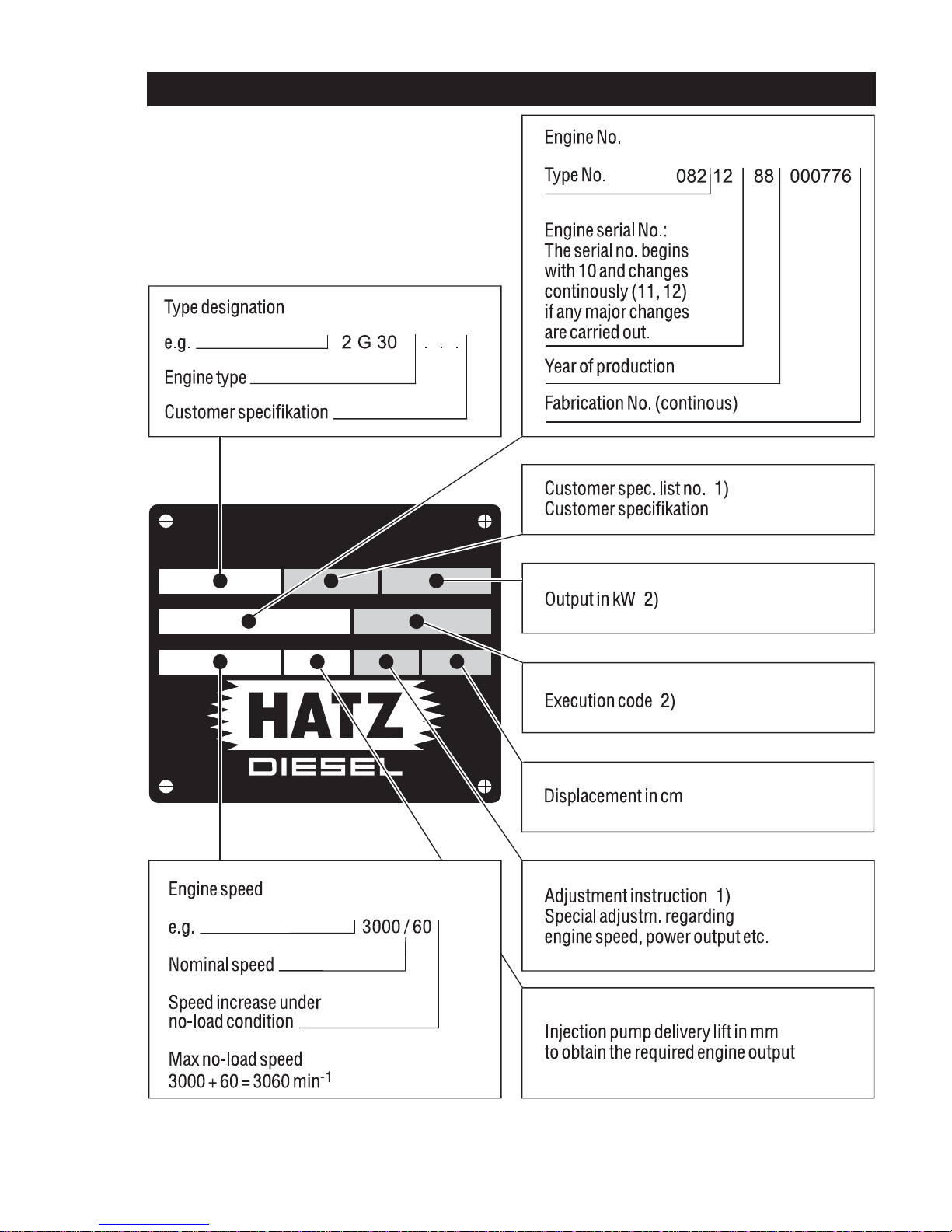
1.3. Type plate data
1) If required
2) In special cases only, e.g. engines acc. to Federal Authority for Automobilism.
2G . ./ 10.92
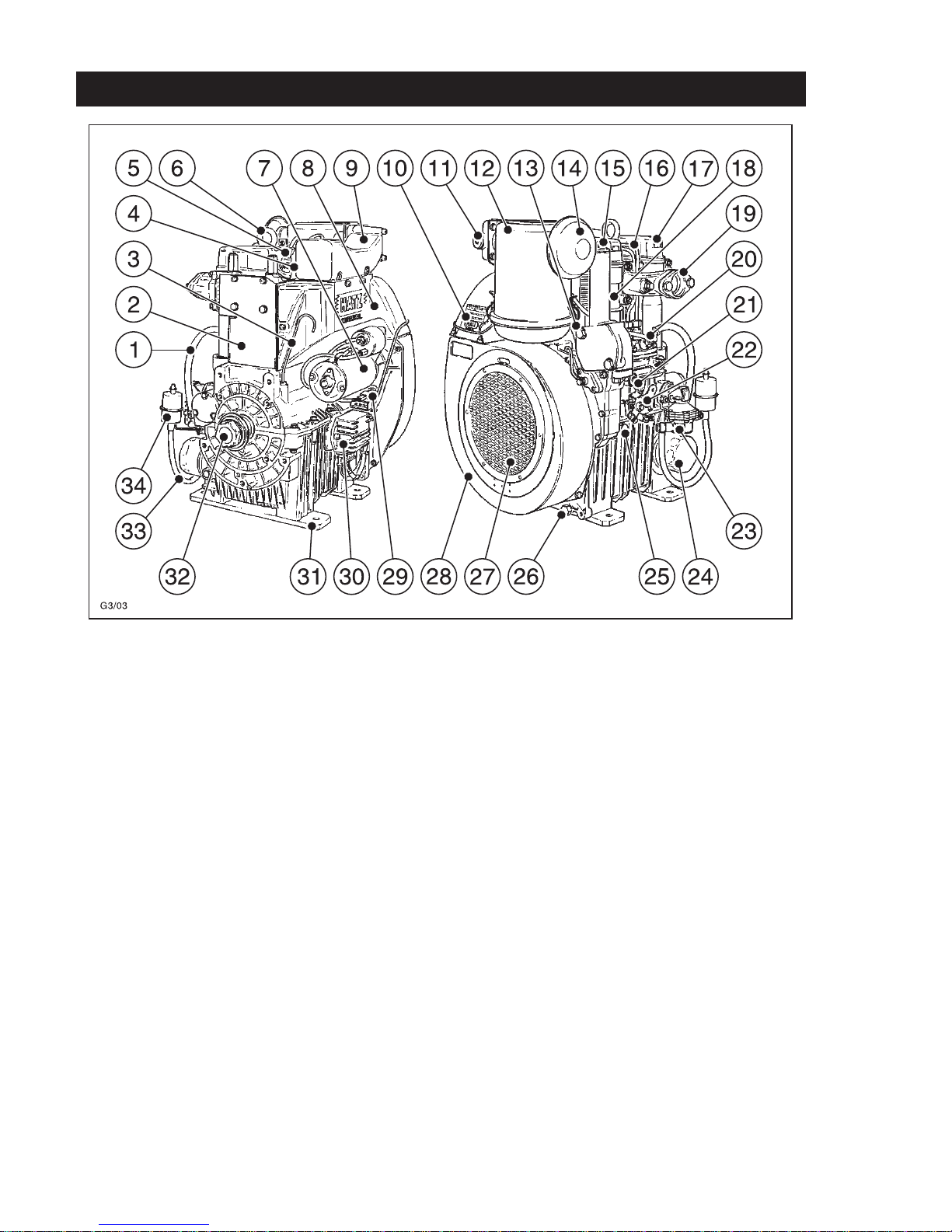
1 Fuel line
(Feed pump - fuel injection pump)
2 Air deflector
3 Oil dipstick
4 Fuel return line
5 Injector
6 Lifting eye-bolt
7 Starter motor
8 Air guide
9 Air intake manifold
10 Type plate
11 Glow plug *
12 Oilbath-airfilter *
13 Oil-pressure switch
14 Rain protection cap *
15 Oil filler cap
16 Fuel pressure pipe
17 Cylinder head cover
18 Lubricating oil line
19 Exhaust manifold
20 Fuel injection pump
21 Stop lever
22 Speed control lever
23 Fuel feed pump
24 Lub.-oil filter
25 Extra fuel device *
26 Oil drain plug
27 Guard
28 Air guide housing
29 Separable connector
30 Voltage regulator
31 Engine mount
32 Crankshaft - Power-take-off
33 Fuel line (Fuel filter - feed pump)
34 Fuel filter
1.2. Engine illustration
* not existing in every engine model

2. Additional equipment

2.1.1. Fuel tank
-2-
Preparations: Dismantling:
- Disconnect the fuel-supply line „1“ with
clamping device - 2 - and pull it off the
fuel filter.
- Pull off the fuel return line „2“ .
- Remove parts # „3“ ... „12“
Inspection / Repair:
- Visual inspection.
- Maintenance work as per operating
manual.
Assembly:
- Follow the reverse # procedure when
assembling.
- Remove the clamping device - 2 - .
- Refer to the Operating Manual for further
information.
2G . ./ 10.92
2.1.2. Fuel filter
-2-
Preparations: Dismantling:
- Disconnect the fuel supply line „1“ with
clamping device - 2 - and pull it off the
fuel filter.
- Remove parts # „13“ ... „22“ , dependent
upon model and requirements.
Inspection / Repair:
- Visual inspection.
- Maintenance work as per Operating
Manual.
Assembly:
- Follow the reverse # procedure when
assembling.
Do not overtighten the clamp clip on the
filter.
- Refer to the Operating Manual for further
information.
2.1. Fuel supply system

2.1
2.1.1.
2.1.2.
10 11 3 4
12 3 4 7 2
5 6
5
2
1
20
21
19
21
22
17
13
20
21
15
16
18
22
17
14

2G . ./ 10.92
-2-
Preparations: Dismantling:
- Disconnect the fuel supply line „32” with
clamping device - 2 -and pull it off the
fuel feed pump.
- Remove parts # ,.33“ ... „40“..
Inspection / repair:
This is only required if irregularities which
could be attributable to the feed pump
have been noted when operating the engine (poor suction/pumping action owing
to defect, soiled strainer or leaks)
- Visual inspection for wear and tear, etc.
(Chapt. 5.6)
Assembly:
- Follow the reverse # procedure when
assembling.
Pay attention to adjustment of pump lift.
Chapt. 5.6.
- Conduct a leakage or function check by
pumping with the hand lever.
2.1.3. Fuel feed pump

2.1
2.1.3.
33 34 35 34
2
32
38
34 34 33
40
39
36

2G . ./ 10.92
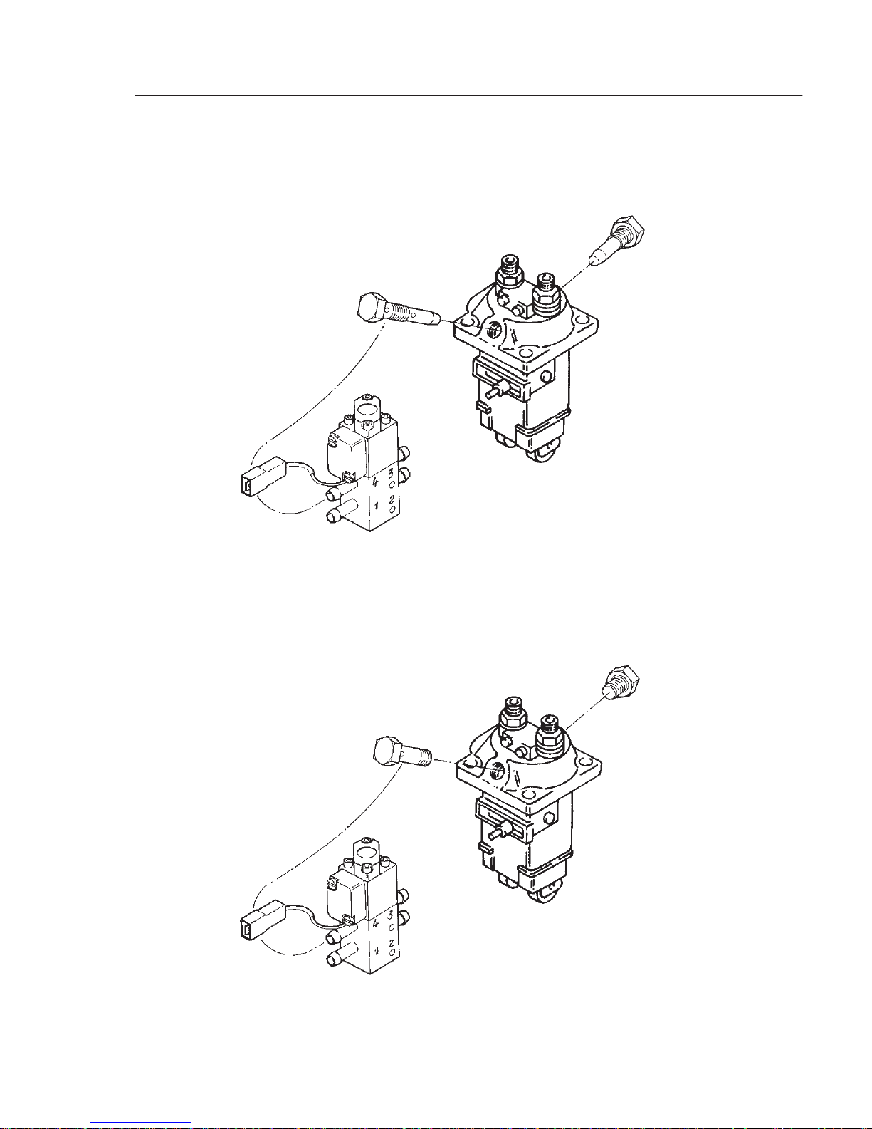
Function:
With fuel solenoid in operation (with electric voltage - see Chapt.10 -) the fuel
flows in the sequence 1 → 2 → 3 → 4
through the solenoid.With shut-off voltage „Stop” the direction of flow is 4 → 3
→ 2 → 1; the injection pump is therefore
sucked empty.
-2-
Preparations: Dismantling:
- Dismantle the fuel supply line with
clamping device - 2 -
Inspection / repair:
- Visual inspection
- Inspection of function
Chapt. 6.2.2.
Assembly:
- Follow the reverse # when assembling.
Note:
If subsequent installation of fuel solenoid
is requested. the injection pump used
must have a small suction chamber, see
sketch B.This allows the engine to come
to a standstill after 10 to 15 seconds.
If the existing injection pump has a big
suction chamber.see sketch A, the
volume must be reduced by using longer
banjo bolts and cap screws.
This advice is also applicable if injection
pump is replaced.
2.1.4. Fuel solenoid
(2-4 ways solenoid)
2.1
2.1.4.
039 557 00
039 514 00
PFR 2K 60A 493
PFR 2K 60A 511
490 214 00
PFR 2K 60A 493
PFR 2K 60A 515
039 557 10

2G . ./ 10.92
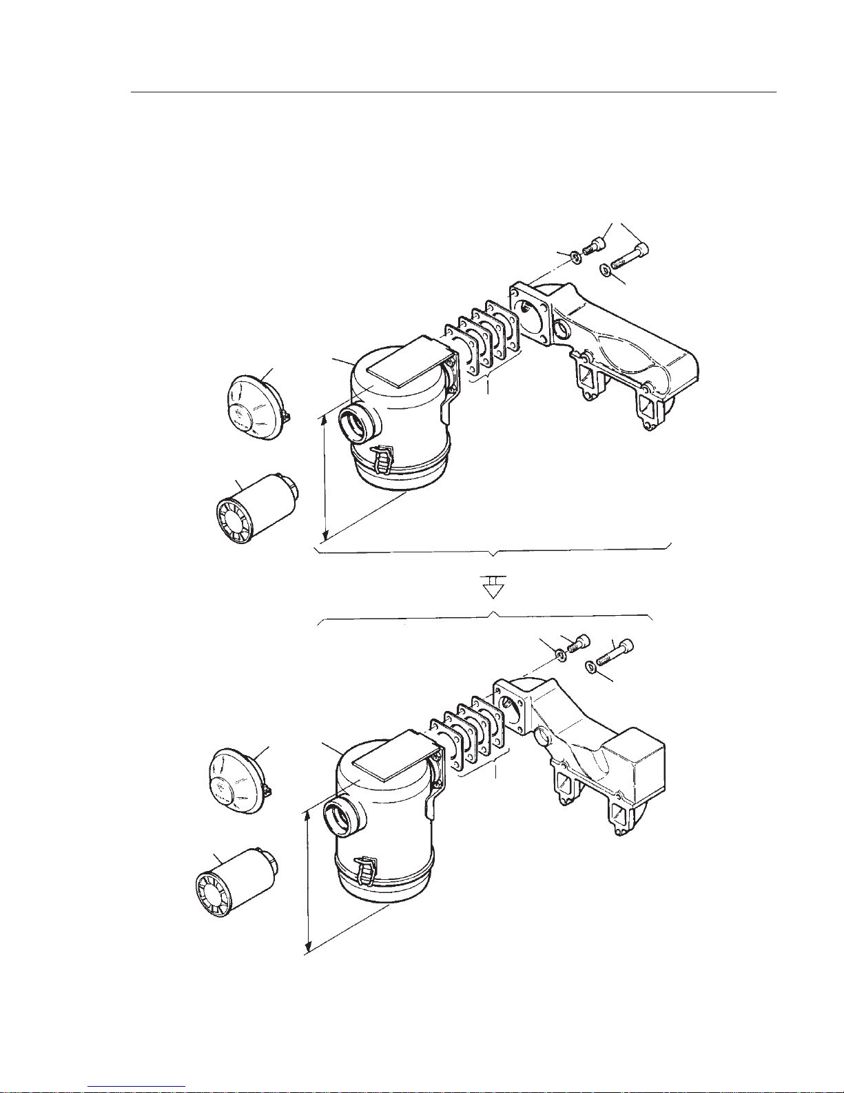
2.2.1. Oilbath-airfilter
–
Preparations: –
Dismantling:
- Remove parts # „1“ ... „4“.
Inspection / repair:
- Visual inspection, especially for plane
contact surface.
- Maintenance work as per instruction
book.
Assembly:
- Follow the reverse # procedure when
assembling.
Note: Filter with h = 218 is only to be installed with elevated suction tube;the
lower filter (h = 192) fits on both variants
of suction tube.
- Refer to the instruction book for further
information.
2.2. Airfilter system
2.2.
2.2.1.
3/1
3/1
3
3
3/2
3/2
192
218
4
4
2
2
1
1
1
2
2
n = 3600
max
min-1
n = 3600
max
min-1
=8212...
=8213... =9110...
<
<<

2G . ./ 10.92
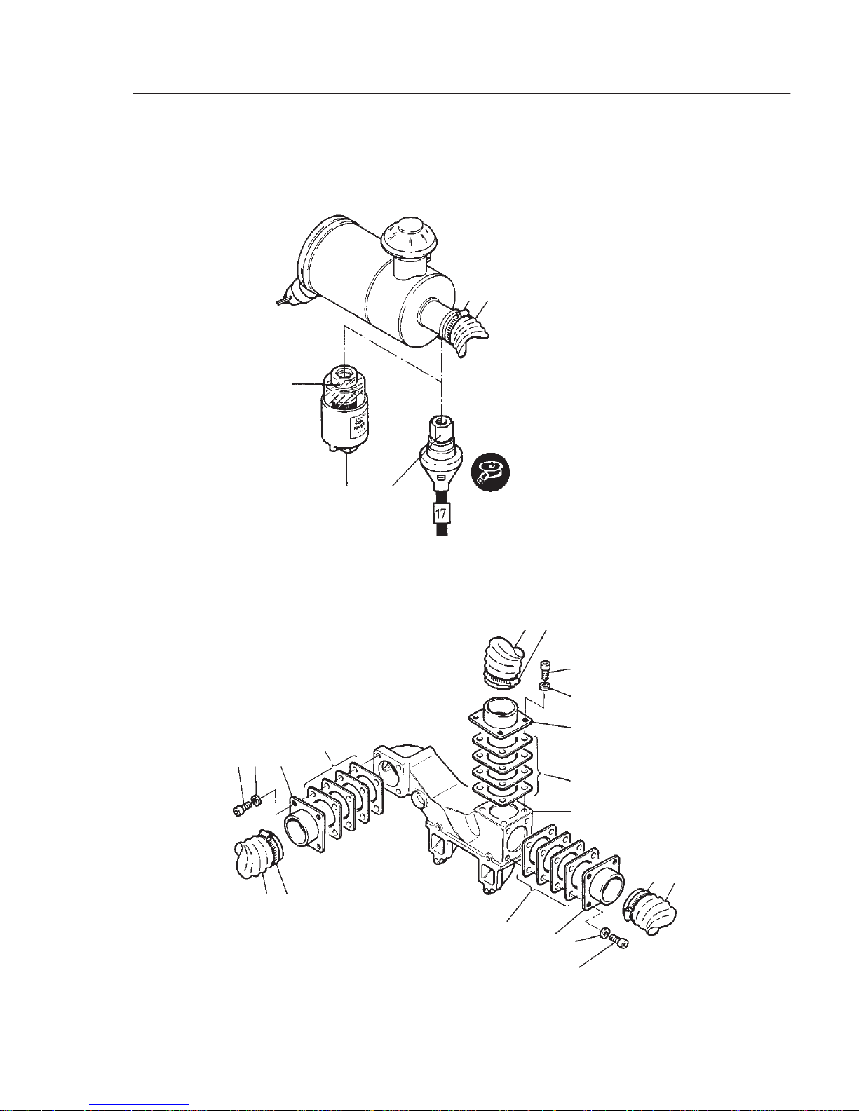
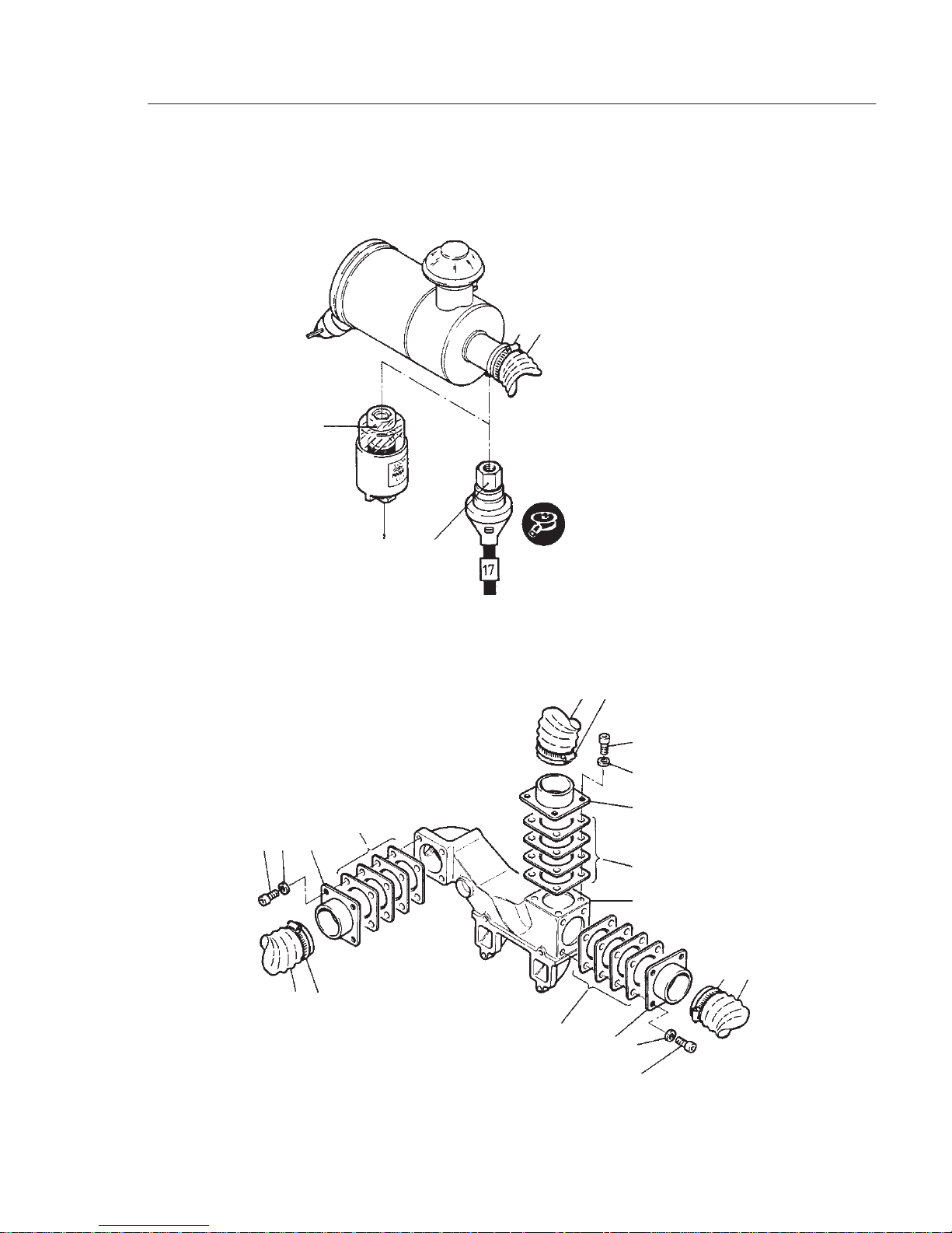
2.2.2. Dr y-type airfilter
(not mounted directly
onto engine!)
–
Preparations: Dismantling:
- Release the hose clips „1”.
- Remove parts # „2” ... „6”.
Inspection / repair:
- Visual inspection.
- Maintenance work as per instruction
book.
Assembly:
- Follow the reverse # procedure when
assembling.
Note:
Check the hose connections at the clean
air side (between engine and filter) for
leaks.
Use only original parts !
- Refer to the instruction book for further
information.
2.2.3. Maintenance indicator,
mechanical (for dry-type
airfilters only)
–
Preparations: Dismantling:
- Unscrew the maintenance indicator „8”.
Inspection / repair:
- Visual inspection.
Check the maintenance indicator as
follows:
- Generate a vacuum on the maintenance
indicator by sucking forcefully.The visible red area must engage.If necessary,
renew the maintenance indicator.
- Before starting up, unlock the service in-
dicator with the reset knob „9”.
Assembly:
- Follow the reverse # procedure when
assembling.
- Refer to the instruction book for further
information
2.2.
2.2.2
2.2.3.
2.2.4..
1 2
8
9 10
3 4 5
2 1
6
5 4
2 1
3
4
5
6
7
1 2
6
3

2G . ./ 10.92
–
Preparations: Dismantling:
- Disconnect the cable connection from
the electrical system.
Note the circuit diagram or wiring
diagram!
Chapt. 10.
- Unscrew the maintenance switch „10”.
Inspection / repair:
- Visual inspection.
Check the maintenance switch as follows:
- Connect the maintenance switch to the
electrical system.The threaded connector must be grounded (battery minus).
- Tur n the switch key to position I.
- Generate a vacuum on the maintenance
switch by sucking forcefully. The indicator lamp on the dashboard console must
light.
- If there is no reaction, check the cable
connections and, if necessary, check the
bulb and/or renew the maintenance
switch.
Assembly:
- Follow the reverse # procedure when
assembling.
- Connect the cable connection to the
electrical system.
Note the circuit diagram or wiring diagram !
Chapt. 10.
- Refer to the instruction book for further
information.
2.2.4. Maintenance indicator, electrical
(applicable for dry-type
airfilters only)
2.2.
2.2.2
2.2.3.
2.2.4..
1 2
8
9 10
3 4 5
2 1
6
5 4
2 1
3
4
5
6
7
1 2
6
3

2G . ./ 10.92
2.3.1. Exhaust silencer and
exhaust pipes
–
Preparations: Dismantling:
- Remove the parts dependent upon version and as required.
Inspection / repair:
- Visual inspection.
Assembly:
- Follow the reverse procedure when
assembling.
Note:
If a new package of gaskets is installed,
absolute attention must be paid to the two
creased sheet metal radiators „A” of the
5-fold gasket set (per cylinder) to point to
the exhaust elbow respectively to the
exhaust silencer. See table 2.3.1. If the
exhaust manifold is continued from elbow.
a 4-fold package of gaskets must be
used.The two creased sheet metal radiators „B” must point with the convex side in
directon of the silencer.See table 2.3.1.
Mount fixing nuts with high-temperature
paste J. Chapt. 9.2.
2.3. Exhaust system
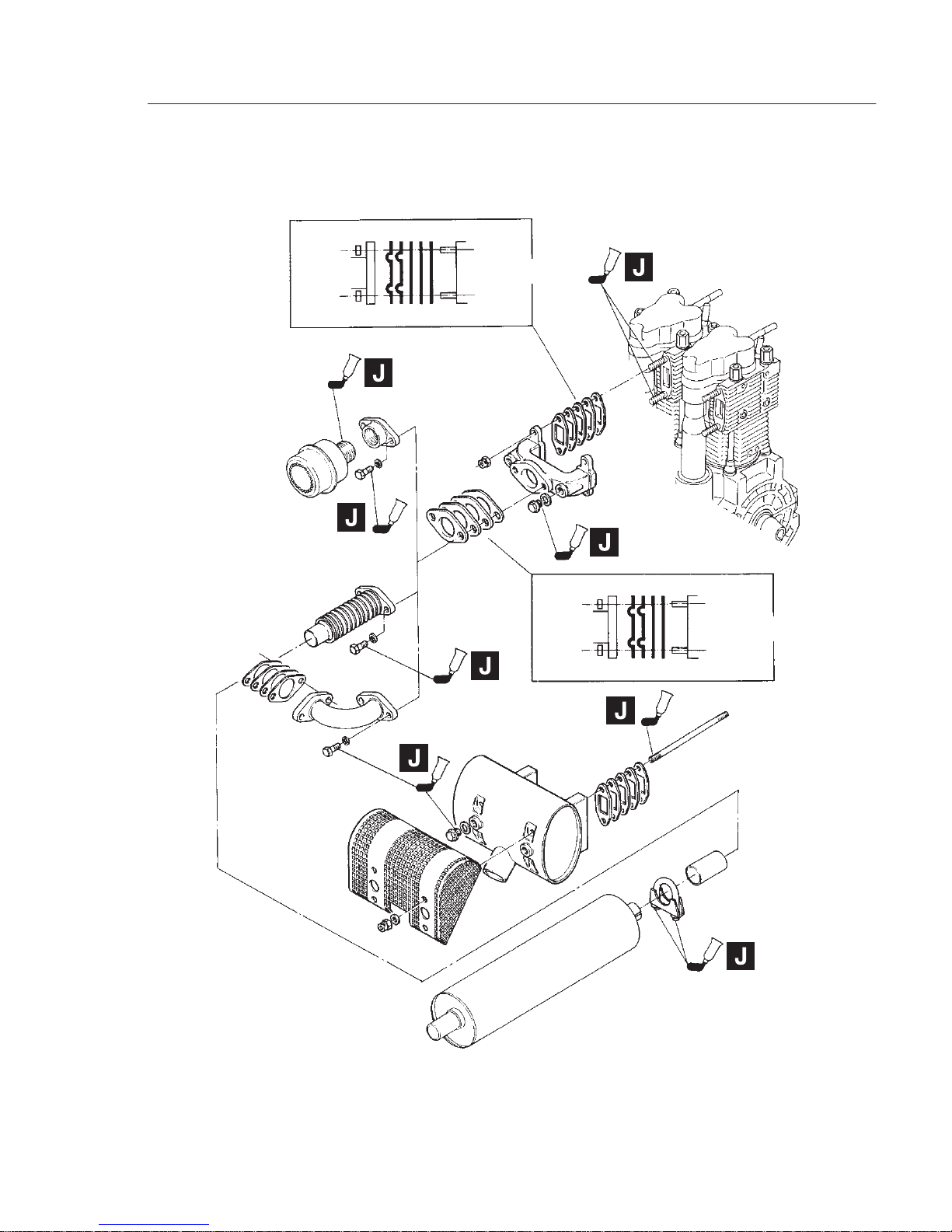
2.3.
2.3.1.
B B
A A
Exhaust
A
A
B
B
Cylinder head
Exhaust
Exhaust manifold

2G . ./ 10.92
2.4.1. Starter
–
Preparations: Dismantling:
- Disconnect the battery.
Note the order - / + !
- Disconnect the cable connections from
electrical system.
Note the circuit diagram or wiring
diagram !
Chapt. 10.
- Remove parts # .,1“ ... „3“
Inspection / repair:
- Visual inspection
If a more extensive repair is necessary,
contact your nearest specialist workshop or HATZ agent.
Assembly:
- Follow the reverse # procedure when
assembling.
- Connect the cable connections to the
electrical system.
Note the circuit diagram or wiring
diagram !
Chapt. 10.
- Refer to the instruction book for further
information.
2.4.2. Alternator
Attention:
Magnetic ring „5” and coil „9” are identical
for the 12 V- and 24 V - version; only a
special regulator switch is inserted
(Chapt. 2.4.3.)
–
Preparations: Chapt. 3.5.2.
Dismantling:
- Disconnect the battery.
Note the order - / + !
- Disconnect the cable connections from
the voltage regulator.
Note the circuit diagram or wiring
diagram !
Chapt. 10.
- Remove parts # „4” ... „10” .
Inspection / repair :
- Visual inspection.
- Chapt. 4.8.1.
- Chapt. 6.4.1.
Assembly:
- Follow the reverse # procedure when
assembling.
- Connect the cable connections to the
electrical system.
Note the circuit diagram or wiring
diagram !
Chapt. 10.
- Refer to the instruction book for further
information.
2.4. Electrical equipment

2.4.
2.4.1.
2.4.2.
2.4.3.
2.4.4.
2.4.5.
13
13
14 5 4
3
6 7 8 10
12 2 1 11
 Loading...