

Hatz Diesel 2-4L41C, 2-4M41, 4L42C, 4M42 Instruction Book
INSTRUCTION BOOK
433 402 07 - ENG - 06.08 - 2
Printed in Germany
33
2-4L41C
2-4M41.
4L42C
4M42
A new HATZ Diesel engine - working for you
This engine is intended only for the purpose determined and tested by the manufacturer of the
equipment in which it is installed. Using it in any other manner contravenes the intended purpose.
For danger and damage due to this, Motorenfabrik HATZ assumes no liability. The risk is with the
user only.
Use of this engine in the intended manner presupposes compliance with the maintenance and repair
instructions laid down for it. Noncompliance leads to engine breakdown.
Please do not fail to read this operating manual before starting the engine. This will help you to avoid
accidents, ensure that you operate the engine correctly and assist you in complying with the maintenance intervals in order to ensure long-lasting, reliable performance.
Please pass this Instruction Manual on to the next user or to the following engine owner.
Always have service work performed by qualified specialists. To this effect, we recommend that you
consult one of the 500 HATZ service stations. There, your engine is repaired by staff who constantly
undergo training and who use both original HATZ spare parts and HATZ tools. The world-wide HATZ
service network is also available to you for consultation and spare parts supply.
For the address of your nearest HATZ service station, please refer to the attached list or the internet
under: www.hatz-diesel.com
The installation of inappropriate spare parts may cause problems. We cannnot accept any liability for
damage or consequential damage resulting therefrom.
Thus, we recommend that you use original HATZ spare parts. These parts are manufactured following the strict HATZ specifications and ensure, thanks to their perfect fit and function, maximum operating reliability. For the reference number, please consult the attached spare part list or the internet
under: www.hatz-diesel.com. Please take the complete spare parts kits in Table M00 into account.
We reserve the right to make modifications in the course of technical progress.
MOTORENFABRIK HATZ GMBH & CO KG
1

Page
1. Important notes on safe operation
of the engine 3
2. Description of engine 5
3. General information 9
3.1. Technical data 9
3.2. Transport 10
3.3 Installation instructions 10
3.4. Load on engine 10
3.5. Type plate 10
4. Operation 11
4.1. Before initial start-up 11
4.1.1. Engine oil 11
4.1.2. Fuel 12
4.2. Starting the engine 13
4.2.1. Starting with the electric starter 14
4.2.2. Emergency starting 16
4.2.3. Starting with handle 16
4.2.4. Starting with the handle with
kick-back damping 18
4.3. Stopping the engine 19
5. Maintenance 20
5.1. Maintenance summary 20
5.2. Maintenance every 8 – 15
hours of operation 23
5.2.1. Check engine oil level 23
5.2.2. Check combustion air intake area 23
5.2.3. Check the cooling air system 25
Page
5.3. Maintenance every 250
hours of operation 25
5.3.1. Engine oil change 25
5.3.2. Cleaning cooling fan, cooling fins
and oil cooler 26
5.3.3. Checking threaded connections 28
5.3.4. Cleaning of mesh insert in
exhaust pipe 28
5.3.5. Check water trap 29
5.4. Maintenance every 500
hours of operation 29
5.4.1. Replace fuel pre-filter 29
5.4.2. Air cleaner maintenance 30
5.4.3. Checking and adjusting
valve clearances 33
5.4.4. Engine oil change 34
5.4.5. Renewing oil filter 34
5.5. Maintenance every 1000
hours of operation 35
5.5.1. Renewing the fuel filter 35
6. Operating checks and repair work 37
6.1. Checking operation of air cleaner
maintenance indicator 37
6.2. Renewing fan drive belt, checking
operation of belt monitor 38
7. Malfunctions – causes and remedies 41
8. Work on the electrical system 45
9. Protective treatment 45
2
Contents
This symbol draws attention to important safety precautions.
Please comply with them most carefully in order to avoid any risk of injury to persons or
damage to materials.
General legal requirements or safety regulations issued by the competent authorities or
industrial accident insurers are also applicable.

1. Important notes on safe operation of the engine
HATZ diesel engines are economical, strongly built and long-lasting. They are therefore frequently
chosen for commercially and industrially operated equipment and machinery.
If the engine forms part of the finished equipment or machine, its manufacturer will take all the applicable safety regulations into account.
Nevertheless, we would like you to note certain additional comments on operating safety which
follow. Depending on the manner in which the engine is installed and its intended application, the
equipment manufacturer or operator may have to attach additional safety devices and prohibit potentially hazardous aspects of operation, for example:
– Exhaust system components as well as the surface of the engine will naturally be hot and must not
be touched while the engine is running or until it has cooled down after being stopped.
– Faulty wiring or incorrect operation of electrical equipment may lead to sparks forming, and must
be avoided as a potential fire hazard.
– Rotating parts must be shielded so that they cannot be touched accidentally when the engine is in-
stalled in other equipment or machinery.
Guards are available from HATZ to protect belt drives for cooling fans and generators.
– Before attempting to start the engine it is essential to have studied the starting information in the
Instruction Book.
– Mechanical starting devices must not be used by children or persons of insufficient physical
strength.
– In order to benefit from the advantages of the starting handle with kick-back damping, it must be
used precisely as recommended in this Instruction Book.
– Before starting the engine, ensure that all the specified protective guards are in place.
– The engine must only be operated, serviced or repaired by persons who have received the appro-
priate training.
– Keep the starting handle and the key out of reach of unauthorized persons.
– Do not run the engine in closed or badly ventilated rooms.
Do not breath in emissions – danger of poisoning!
– Also fuel and lubricants could contain poisonous components. Please follow the instructions of the
mineral oil producer.
3

Important notes on safe operation of the engine
– Stop the engine before performing any maintenance, cleaning- and repair work.
– Stop the engine before refuelling.
Never refuel near a naked flame or sparks which could start a fire. Don’t smoke. Don’t spill fuel.
– Keep explosive materials as well as flammable materials away from the engine because the exhaust
gets very hot during operation.
– Wear close-fitting clothing when working on the engine while it is running.
Please don’t wear necklaces, bracelets or any other things which you could get caught with.
– Please pay attention to all advice- and warning stickers placed on the engine and keep them in legi-
ble condition. Contact your next HATZ service station, if a sticker comes off or is illegible and ask
for a new one.
– Note that any unauthorized modifications to the engine absolve its manufacturer from liability for
the consequences.
Regular servicing in accordance with the details provided in this Instruction Book is essential to keep
the engine operating reliably.
In case of doubt, always consult your nearest HATZ service station before starting the engine.
4
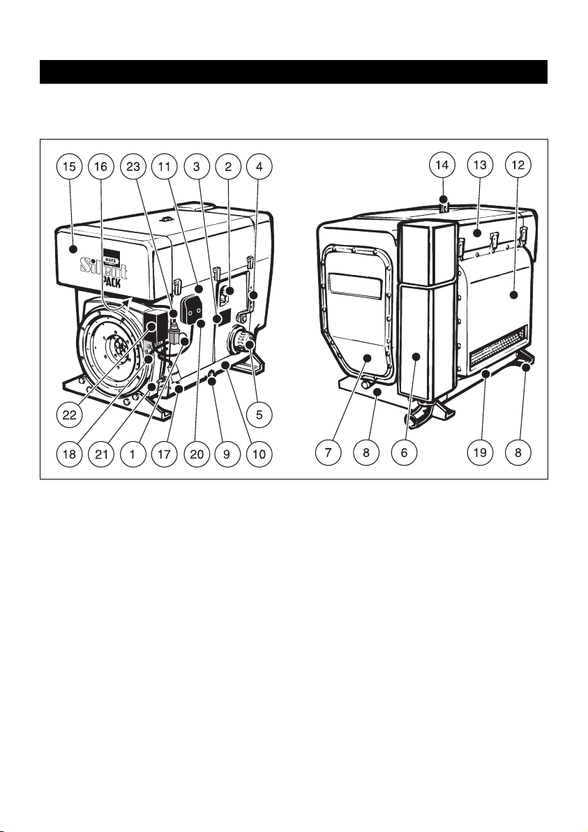
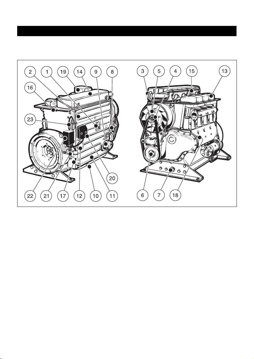
2. Description of engine
Fully encapsulated „Silent Pack“ version
Engine 2 ...4L41C
5
1 Access cover for fuel delivery pump
2 Oil filler pipe and dipstick
3 Type plate
4 Speed control lever
5 Replaceable-element oil filter
6 Exhaust silencer (in capsule)
7 Cover for air guide housing
(Access to fan drive belt)
8 Engine support feet
9 Oil drain plug
10 Cover plate, control side
11 Side panel
12 Air outlet duct
13 Capsule hood
14 Suspension lug (retractable),
max. load 5000 N
15 Air intake duct for capsule
16 Combustion air intake aperture
17 Fuel feed line line with fuel pre-filter
18 Fuel return line
19 Cover plate, air outlet side
20 Central plug for electrical system
21 Battery connections
22 Power-Box
23 Electrical maintenance switch for
air cleaner
1
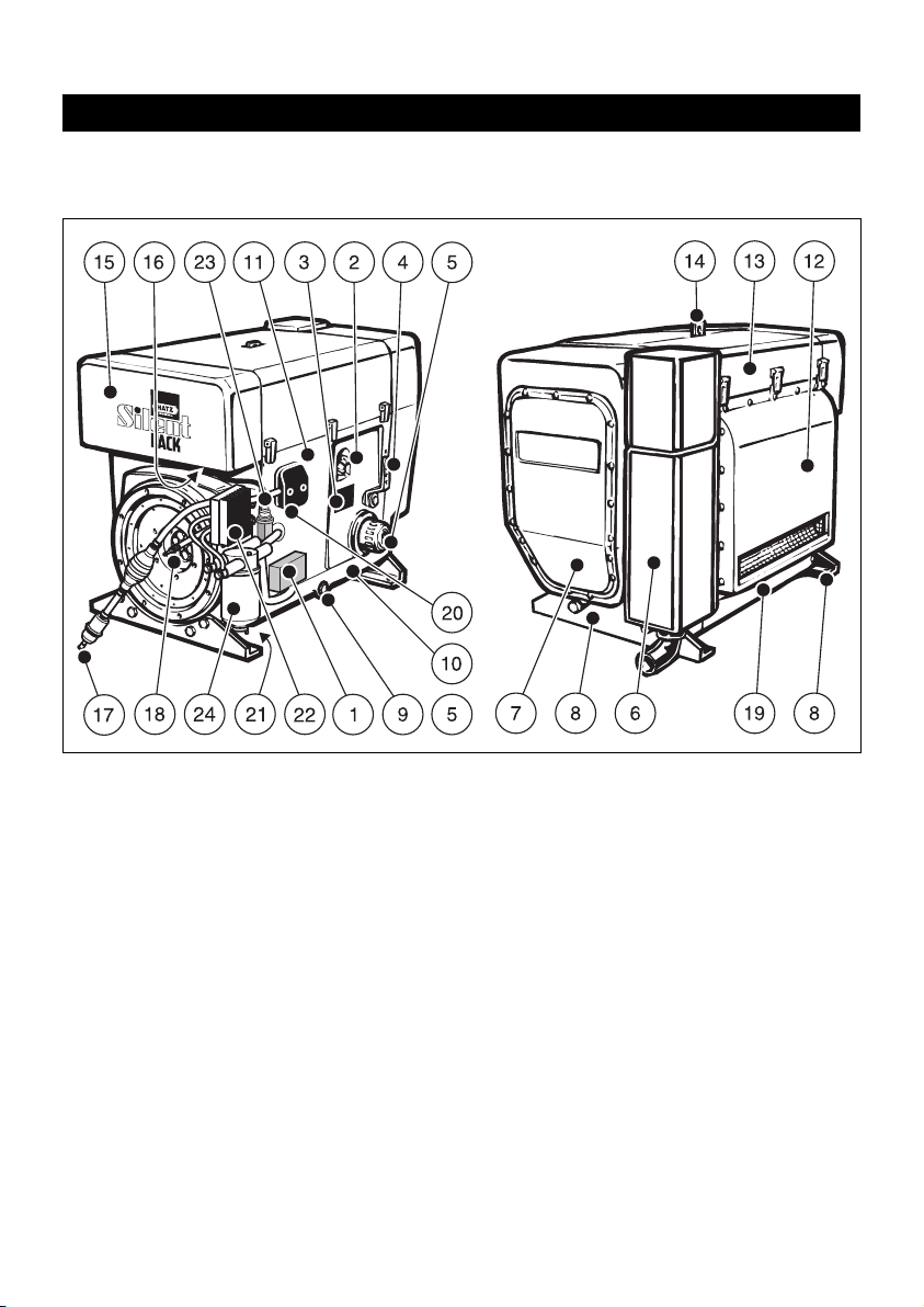
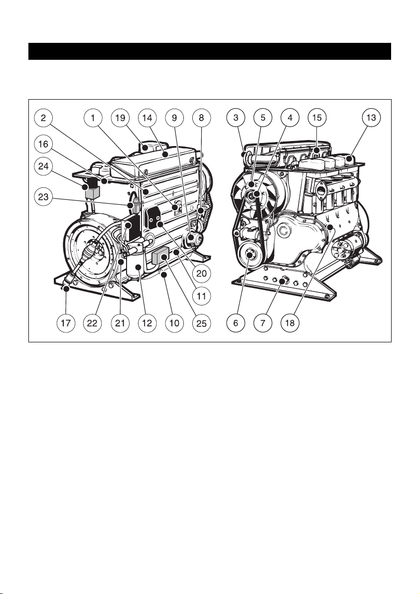
Description of engine
Fully encapsulated „Silent Pack“ version
Engine 4 L 42 C
6
1 Electronic control unit
2 Oil filler pipe and dipstick
3 Type plate
4 Speed control lever
5 Replaceable-element oil filter
6 Exhaust silencer (in capsule)
7 Cover for air guide housing
(Access to fan drive belt)
8 Engine support feet
9 Oil drain plug
10 Cover plate, control side
11 Side panel
12 Air outlet duct
13 Capsule hood
14 Suspension lug (retractable),
max. load 5000 N
15 Air intake duct for capsule
16 Combustion air intake aperture
17 Fuel feed line with fuel pre-filter and
manual fuel pump
18 Fuel return line
19 Cover plate, air outlet side
20 Central plug for electrical system
21 Battery connections
22 Power-Box
23 Electrical maintenance switch for
air cleaner
24 Fuel filter
2
Description of engine
Standard version
Engine 2 ... 4 M 41 • 2 ... 4 M 41 Z
7
1 Oil filler pipe and dipstick
2 Side panel
3 Combustion air intake aperture
4 Cooling fan drive belt
5 Cooling fan with alternator attached
6 1/2-inch intl. hex socket for turning over
engine
7 Oil drain plug
8 Speed control lever
9 Replaceable-element oil filter
10 Oil drain plug (if sump is fitted)
11 Cooling air duct for engine oil cooler
12 Access cover for fuel delivery pump
13 Cylinder head cover
14 Air cleaner cover
15 Suspension lug, max. load 5000 N
16 Fuel return line
17 Fuel feed line with fuel pre-filter
18 Type plate
19 Exhaust silencer
20 Central plug for electrical system
21 Battery connections
22 Power-Box
23 Electrical maintenance switch for
air cleaner
3
Description of engine
Standard version
Engine 4 M 42
8
4
1 Oil filler pipe and dipstick
2 Side panel
3 Combustion air intake aperture
4 Cooling fan drive belt
5 Cooling fan with alternator attached
6 1/2-inch intl. hex socket for turning over
engine
7 Oil drain plug
8 Speed control lever
9 Replaceable-element oil filter
10 Oil drain plug (if sump is fitted)
11 Cooling air duct for engine oil cooler
12 Fuel filter
13 Cylinder head cover
14 Air cleaner cover
15 Suspension lug, max. load 5000 N
16 Fuel return line
17 Fuel feed line with fuel pre-filter and
manual fuel pump
18 Type plate
19 Exhaust silencer
20 Central plug for electrical system
21 Battery connections
22 Power-Box
23 Electrical maintenance switch for
air cleaner
24 Exhaust gas return valve (EGR)
25 Electronic control unit

9
3. General information
3.1. Technical data
2L41C 3L41C 4L41C / 4L42C
2 M 41. 3 M 41. 4 M 41. / 4 M 42.
Type Air-cooled, four-stroke diesel engine
Combustion method Direct fuel injection
Number of cylinders 2 3 4
Bore/stroke mm 102 / 105 102 / 105 102 / 105
Displacement cm³ 1716 2574 3432
Engine oil pressure
Oil temperature 100 ± 20°C min. 0.6 bar at 850 r.p.m.
Consumption of lubrication max. 1 % of fuel consumption
oil after running-in period at full-load
Direction of rotation Counterclockwise, looking at flywheel
Valve clearance (at 10 - 30 °C)
Inlet/exhaust mm 0.10
Net weight
.M41 258 308 373
.M41 Z approx. 263 315 388
4M42 kg 378
.L41 C 303 363 433
4L42 C 438
Max. angle from vertical in any with and without with without only with
direction (in continuous operation) sump sump sump
Control side 30°
1)
30° 1)25°
1)
25°
1)
Air outlet side 30°
1)
30° 1)30°
1)
30°
1)
Timing gear side 30°
1)
25° 1)25°
1)
15°
1)
Flywheel side 30°
1)
22° 1)25°
1)
18°
1)
1)
Exceeding these limits causes engine breakdown.
3.2. Transport
A suspension lug is provided as stand-
ard equipment, so that the engine and
its auxiliaries can be lifted safely. It is not
suitable for lifting complete machines or similar to which the engine has been attached, and
this is strictly prohibited. (See Chapter 2.)
3.3. Instructions for installation
The „Manual for Selection and Installation of
Engines“ contains all the information you need if
your engine has not yet been installed on or in
the equipment it is intended to drive, or set up in
its correct operating position. You can obtain a
copy of this manual from your nearest HATZ
service station.
3.4. Load on engine
Operating the engine for a lengthy period offload or at very low loads can affect its running
quality.
We therefore recommend a minimum engine
load of 15 %. If operated at such low loads, it is
best to operate the engine at a significantly higher load for a short period before switching it off.
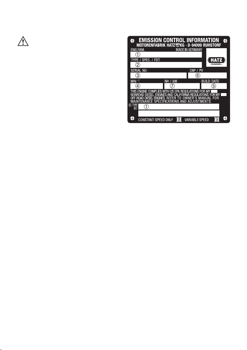
3.5. Type plate
5
The type plate is placed on the crankcase resp.
on the capsule (chapt. 2) and includes the following engine information (pict. 5):
➀ Number of the engine family or of EU appro-
val (only for engines with exhaust gas certificate)
➁ Engine type, customer specification and set-
ting of beginning of delivery
➂ Engine number
➃ Max. engine speed
➄ Manuf. year
➅ Displacement and test procedure for specific
settings
➆ Injection pump delivery lift and engine power
output
➇ “constant speed only” (only for engines with
EPA/CARB exhaust gas certificate)
➈ “variable speed” (only for engines with
EPA/CARB exhaust gas certificate)
For any offer as well as spare part orders it is
necessary to mention these data (also see spare
parts list, page 1).
➁ Engine type and customer specification
➂ Engine number
➃ Max. engine speed.
10
4. Operation
4.1. Before first start-up
Engines are normally delivered without any fuel
or oil.
4.1.1. Engine oil
Oil quality
Qualified are all trademark oils which fulfil at
least one of the following specifications:
ACEA – B2 / E2 or more significant
API – CD / CE / CF / CF-4 / CG-4 or more
significant.
If engine oils with low quality standard are being
used, the intervals of changing the engine oil
have to be reduced from 250 to 150 resp. 500 to
250 hours of operation, see chapter 5.1.
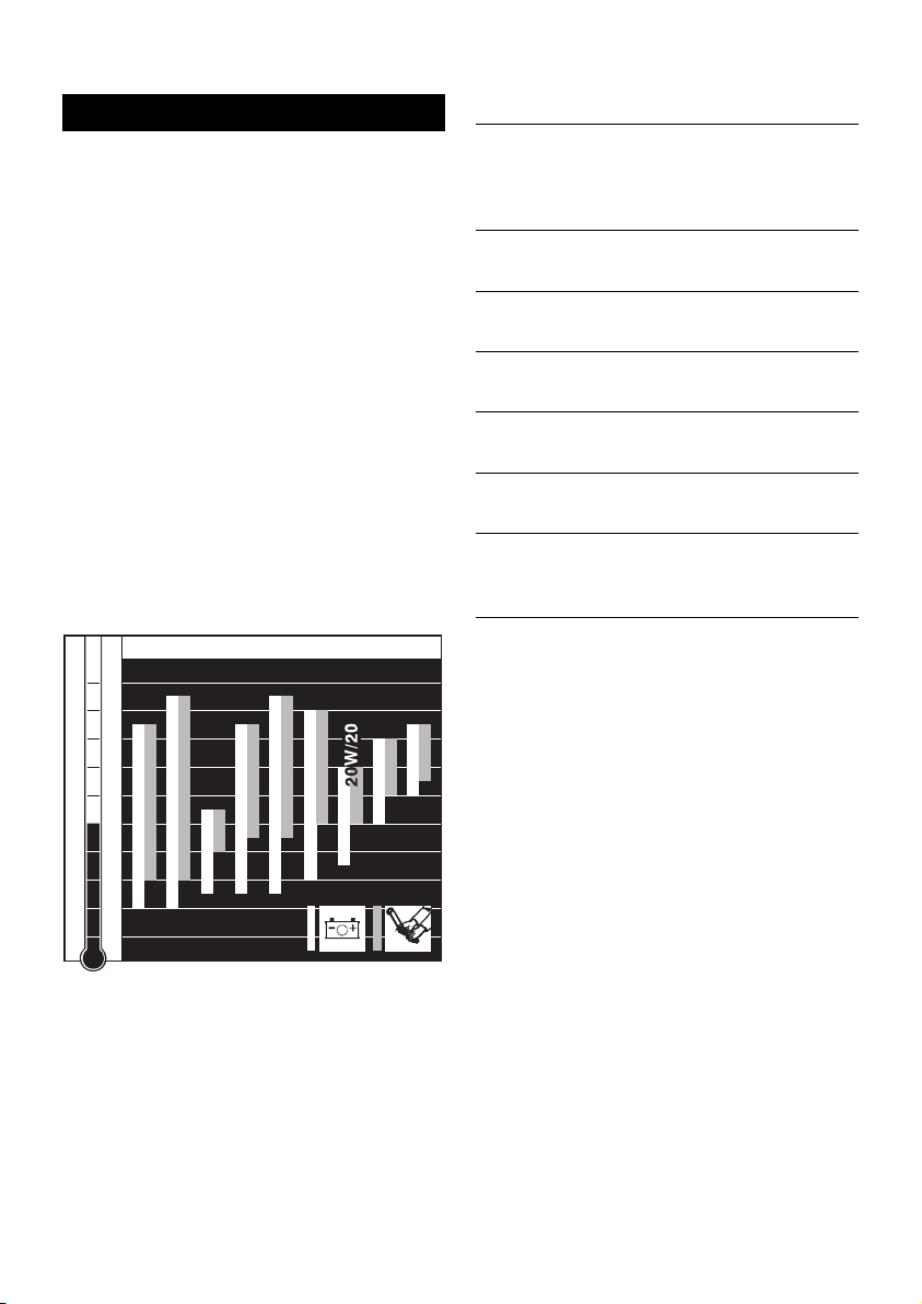
Oil viscosity
6
Choose a suitable oil viscosity according to the
ambient temperature when the engine is started
from cold.
-40
-30
-20
-10
0
10
20
30
40
50
104
86
68
50
32
14
-4
-22
-40
OIL: SAE...
°C°F
5W/30
5W/40
10 W / 4 0
10 W / 3 0
15 W / 4 0
30
40
122
10 W
Engine oil quantities and dipstick markings
dipstick
Engine type Sump
Oil content marking
(liter) (Figure 7,
item 2)
2L41C, 2 M 41 Z
Yes 7.5 C
No 4.5 A
2M41
Yes 8.5 C
No 5.5 A
3L41C, 3M41 Z
Yes 10.5 D
No 8.0 A
3M41
Yes 11.0 D
No 8.5 A
4L41C, 4L42C Yes 13.0 D
4 M 41 Z No – –
Yes 14.0 D
4 M 41, 4 M 42
No – –
Note:
The engine oil contents stated here are to be
regarded as approximate.
In all cases, the MAX marking on the dipstick
should be complied with.
11
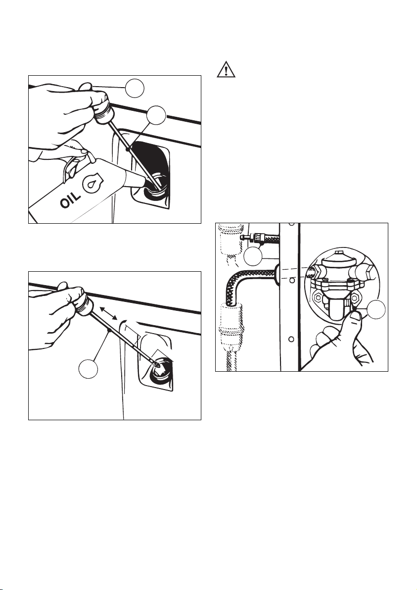
The engine should be in a horizontal position
before adding oil or checking the oil level.
7
– Pull out dipstick „1“.
8
– Add engine oil up to the MAX mark on dipstick
„1“ (Figures 7 and 8).
– Run the engine for a short time, then check oil
level again and correct if necessary.
1327/2
L3/47
MAX
MIN
1
1
L3/45
A
2
4.1.2. Fuel
Stop the engine before refilling the
fuel tank. Never refuel near a naked
flame or sparks which could start a fire. Don’t
smoke. Use only pure fuel and clean filling
equipment. Take care not to spill fuel.
All diesel oils sold as fuel and complying with
the following minimum specifications can be
used:
EN 590 or
BS 2869 A1 / A2 or
ASTM D 975 - 1D / 2D
Standard version
9
– Before the engine is first started, or if the fuel
system was run dry, prime the fuel delivery
pump at lever „1“ until fuel is heard to flow
back through the return line „2“ to the fuel
tank.
Important !
Remember to replace the access cover for the
fuel delivery pump in the side panel of the engine enclosure after priming the pump (Chap. 2).
L3/46
2
1
12

Models with manual fuel pump
(On 4L42C and 4M42 engines only)
10
– Place a suitable vessel under the filter to trap
escaping fuel.
– Open the vent screw 1 by approx. one turn.
11
– Compress and release rubber ball repeatedly,
until fuel escapes from the vent screw 1.
– Close vent screw 1, then actuate rubber ball
another two times.
1
1
Low temperature resistance
At low temperatures, the viscosity of Diesel fuel
increases. This may result in clogging of the fuel
system. Thus, winter fuel must be used at outside temperatures below 0 °C, or petroleum
must be added in time.
4.2. Starting
Do not run the engine in closed or
badly ventilated rooms – danger of
poisoning! Before the engine is started, always
make sure that nobody is in the danger area
(moving parts on engine or machinery) and
that all safety guards are in place.
12
Never use any spray starting aids
L3/250
050 145 00
Lowest ambient
temperature when
starting, in °C
Paraffin content for:
Summer Winter
fuel fuel
0 up to –10 20 % –
–10 up to –15 30 % –
–15 up to –20 50 % 20 %
–20 up to –30 – 50 %
13
If possible, disengage the engine from any
driven equipment.
The auxiliary equipment should always be placed
in neutral.
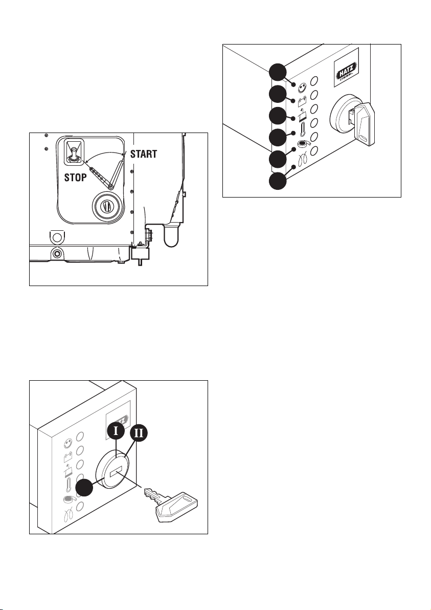
4.2.1. Starting with the electric starter
13
– Move the speed control lever to the 1/2 START
or max. START position, according to requirements and starting conditions.
Note that a lower speed setting will cause less
exhaust smoke when starting.
14
– Insert the key to its stop and turn it to
position I.
0
15
– Battery charge telltale „2“ and oil pressure
warning „3“ must light up.
– Turn start key to position II (Fig. 14).
– As soon as the engine runs, release the start
key. It must return to position I by itself and
remain in this position during operation.
The battery charge telltale and oil pressure
warning must go out immediately after starting. Indicator light „1“ is on when the engine is
in operation.
– The air cleaner maintenance indicator „5“ only
lights up during operation if the air cleaner element needs to be cleaned or renewed (Fig. 15,
see chapter 5.4.2.).
– The engine temperature display „4“ (additional
equipment) lights up if the temperature at the
cylinder head becomes too high.
Switch off the engine and trace and eliminate the cause of the problem, see chapter 7.
– Always turn the start key back to position 0
before re-starting the engine. The repeat lock
in the ignition lock prevents the starter motor
from engaging and possibly being damaged
while the engine is still running.
1
2
3
4
5
6
14
 Loading...