

Hatz Diesel 2-4L41C, 2-4M41, 4L42C, 4M42 Instruction Book
INSTRUCTION BOOK
433 416 06-USA-EPA IV-CARB
1.08 - 0.1
Printed in Germany
33
2-4L41C
2-4M41.
4L42C
4M42
INCLUDES SUPPLEMENTAL INFORMATION TO THE
OWNER’S MANUAL FOR 2008 AND LATER EPA CERTIFIED
NONROAD COMPRESSION-IGNITION ENGINES
INCLUDES SUPPLEMENTAL INFORMATION TO THE
OWNER’S MANUAL FOR 2008 AND LATER CALIFORNIA
REGULATIONS FOR HEAVY-DUTY OFF-ROAD ENGINES
A new HATZ Diesel engine - working for you
This engine is intended only for the purpose determined and tested by the manufacturer of the
equipment in which it is installed. Using it in any other manner contravenes the intended purpose.
For danger and damage due to this, Motorenfabrik HATZ assumes no liability. The risk is with the
user only. Use of this engine in the intended manner presupposes compliance with the maintenance
and repair instructions laid down for it. Noncompliance leads to engine breakdown.
Please do not fail to read this operating manual before starting the engine. This will help you to avoid
accidents, ensure that you operate the engine correctly and assist you in complying with the maintenance intervals in order to ensure long-lasting, reliable performance.
Please follow all maintenance references carefully including the schedule for 2008 and later
EPA certified nonroad compression-ignition engines and for 2008 and later CARB certified
Heavy-Duty off-road engines to prevent our environment.
Please pass this Instruction Manual on to the next user or to the following engine owner.
The worldwide HATZ Service Network is at your disposal to advise you, supply with spare parts and
undertake servicing work.
You will find the address of your nearest HATZ service station in the enclosed list.
Use only original spare parts from HATZ. Only these parts guarantee a perfect dimensional stability
and quality. The order numbers can be found in the enclosed spare parts list. Please note the spare
part kits shown in Table M00.
We reserve the right to make modifications in the course of technical progress.
MOTORENFABRIK HATZ GMBH & CO KG
1

Contents
Page
1. Important notes on safe operation of the engine 3
2. Description of engine 5
3. General information 9
3.1. Technical data
3.2. Transport
3.3 Installation instructions
3.4. Load on engine
3.5. EPA/CARB-type plates and fuel label
3.6. Emission-related installation
instructions
4. Operation 12
4.1. Before initial start-up
4.2. Starting the engine
4.3. Stopping the engine
5. Maintenance 21
5.1. Maintenance summary
5.2. Maintenance every 8 - 15 hours of operation
5.3. Maintenance every 250 hours of operation
5.4. Maintenance every 500 hours of operation
5.5. Maintenance every 1000 hours of operation
6. Operating checks and repair work 37
6.1. Checking operation of air cleaner maintenance indicator
6.2. Renewing fan drive belt, checking operation of belt monitor
7. Malfunctions – causes and remedies 41
8. Work on the electrical system 45
9. Protective treatment 45
SUPPLEMENTAL INFORMATION TO THE OWNER’S MANUAL FOR 2008 AND LATER
EPA CERTIFIED NONROAD COMPRESSION IGNITION ENGINES 47
SUPPLEMENTAL INFORMATION TO THE OWNER’S MANUAL FOR 2008
AND LATER CALIFORNIA REGULATIONS FOR HEAVY-DUTY OFF-ROAD ENGINES 65
This symbol draws attention to important safety precautions.
Please comply with them most carefully in order to avoid any risk of injury to persons or
damage to materials.
General legal requirements or safety regulations issued by the competent authorities or
industrial accident insurers are also applicable.
2

1. Important notes on safe operation of the engine
HATZ diesel engines are economical, strongly built and long-lasting. They are therefore frequently
chosen for commercially and industrially operated equipment and machinery.
If the engine forms part of the finished equipment or machine, its manufacturer will take all the applicable safety regulations into account.
Nevertheless, we would like you to note certain additional comments on operating safety which
follow. Depending on the manner in which the engine is installed and its intended application, the
equipment manufacturer or operator may have to attach additional safety devices and prohibit potentially hazardous aspects of operation, for example:
– Exhaust system components as well as the surface of the engine will naturally be hot and must not
be touched while the engine is running or until it has cooled down after being stopped.
– Faulty wiring or incorrect operation of electrical equipment may lead to sparks forming, and must
be avoided as a potential fire hazard.
– Rotating parts must be shielded so that they cannot be touched accidentally when the engine is in-
stalled in other equipment or machinery.
Guards are available from HATZ to protect belt drives for cooling fans and generators.
– Before attempting to start the engine it is essential to have studied the starting information in the
Instruction Book.
– Mechanical starting devices must not be used by children or persons of insufficient physical
strength.
– In order to benefit from the advantages of the starting handle with kick-back damping, it must be
used precisely as recommended in this Instruction Book.
– Before starting the engine, ensure that all the specified protective guards are in place.
– The engine must only be operated, serviced or repaired by persons who have received the appro-
priate training.
– Keep the starting handle and the key out of reach of unauthorized persons.
– Do not run the engine in closed or badly ventilated rooms.
Do not breath in emissions – danger of poisoning!
– Also fuel and lubricants could contain poisonous components. Please follow the instructions of the
mineral oil producer.
3

Important notes on safe operation of the engine
– Stop the engine before performing any maintenance, cleaning- and repair work.
– Stop the engine before refuelling.
Never refuel near a naked flame or sparks which could start a fire. Don’t smoke. Don’t spill fuel.
– Keep explosive materials as well as flammable materials away from the engine because the exhaust
gets very hot during operation.
– Wear close-fitting clothing when working on the engine while it is running.
Please don’t wear necklaces, bracelets or any other things which you could get caught with.
– Please pay attention to all advice- and warning stickers placed on the engine and keep them in legi-
ble condition. Contact your next HATZ service station, if a sticker comes off or is illegible and ask
for a new one.
– Note that any unauthorized modifications to the engine absolve its manufacturer from liability for
the consequences.
Regular servicing in accordance with the details provided in this Instruction Book is essential to keep
the operating reliably and to ensure the exhaust quality of the engine.
In case of doubt, always consult your nearest HATZ service station before starting the engine.
4
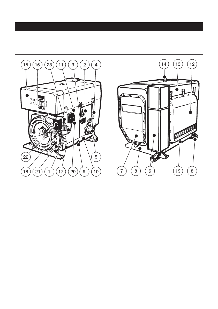
2. Description of engine
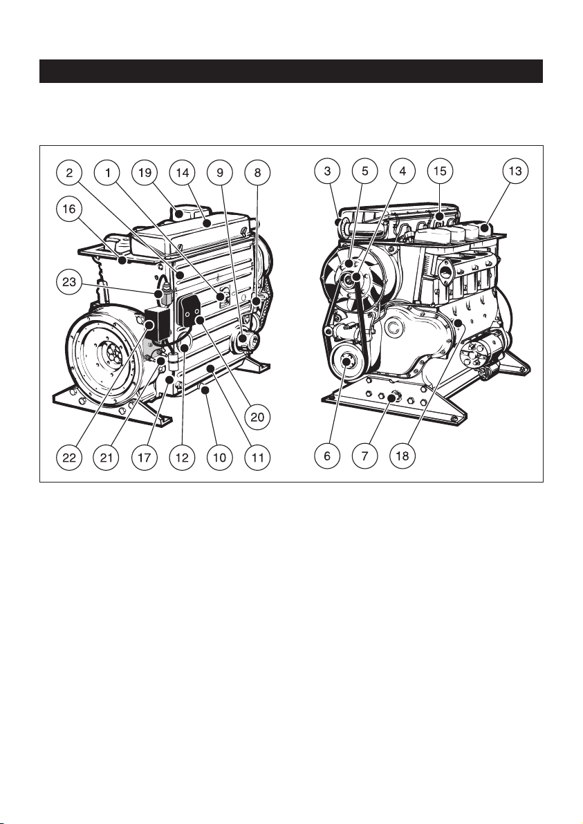
Fully encapsulated „Silent Pack“ version
Engine 2 ...4L41C
5
1
1 Access cover for fuel delivery pump
2 Oil filler pipe and dipstick
3 Type plate
4 Speed control lever
5 Replaceable-element oil filter
6 Exhaust silencer (in capsule)
7 Cover for air guide housing
(Access to fan drive belt)
8 Engine support feet
9 Oil drain plug
10 Cover plate, control side
11 Side panel
12 Air outlet duct
13 Capsule hood
14 Suspension lug (retractable),
max. load 5000 N
15 Air intake duct for capsule
16 Combustion air intake aperture
17 Fuel feed line with fuel pre-filter
18 Fuel return line
19 Cover plate, air outlet side
20 Central plug for electrical system
21 Battery connections
22 Power-Box
23 Electrical maintenance switch for
air cleaner
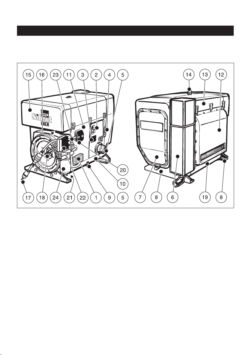
Description of engine
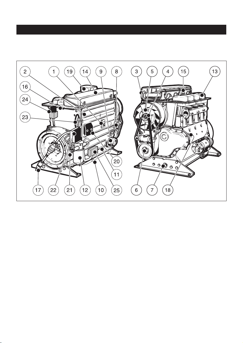
Fully encapsulated „Silent Pack“ version
Engine 4 L 42 C
6
1 Electronic control unit
2 Oil filler pipe and dipstick
3 Type plate
4 Speed control lever
5 Replaceable-element oil filter
6 Exhaust silencer (in capsule)
7 Cover for air guide housing
(Access to fan drive belt)
8 Engine support feet
9 Oil drain plug
10 Cover plate, control side
11 Side panel
12 Air outlet duct
13 Capsule hood
14 Suspension lug (retractable),
max. load 5000 N
15 Air intake duct for capsule
16 Combustion air intake aperture
17 Fuel feed line with fuel pre-filter and
manual fuel pump
18 Fuel return line
19 Cover plate, air outlet side
20 Central plug for electrical system
21 Battery connections
22 Power-Box
23 Electrical maintenance switch for
air cleaner
24 Fuel filter
2
Description of engine
Standard version
Engine 2 ... 4 M 41 • 2 ... 4M41Z
7
3
1 Oil filler pipe and dipstick
2 Side panel
3 Combustion air intake aperture
4 Cooling fan drive belt
5 Cooling fan with alternator attached
6 1/2-inch intl. hex socket for turning over
engine
7 Oil drain plug
8 Speed control lever
9 Replaceable-element oil filter
10 Oil drain plug (if sump is fitted)
11 Cooling air duct for engine oil cooler
12 Access cover for fuel delivery pump
13 Cylinder head cover
14 Air cleaner cover
15 Suspension lug, max. load 5000 N
16 Fuel return line
17 Fuel feed line with fuel pre-filter
18 Type plate
19 Exhaust silencer
20 Central plug for electrical system
21 Battery connections
22 Power-Box
23 Electrical maintenance switch for
air cleaner
Description of engine
Standard version
Engine 4 M 42
8
4
1 Oil filler pipe and dipstick
2 Side panel
3 Combustion air intake aperture
4 Cooling fan drive belt
5 Cooling fan with alternator attached
6 1/2-inch intl. hex socket for turning over
engine
7 Oil drain plug
8 Speed control lever
9 Replaceable-element oil filter
10 Oil drain plug (if sump is fitted)
11 Cooling air duct for engine oil cooler
12 Fuel filter
13 Cylinder head cover
14 Air cleaner cover
15 Suspension lug, max. load 5000 N
16 Fuel return line
17 Fuel feed line with fuel pre-filter and
manual fuel pump
18 Type plate
19 Exhaust silencer
20 Central plug for electrical system
21 Battery connections
22 Power-Box
23 Electrical maintenance switch for
air cleaner
24 Exhaust gas return valve (EGR)
25 Electronic control unit

9
3. General information
3.1. Technical data
2L41C 3L41C 4L41C / 4L42C
2 M 41. 3 M 41. 4 M 41. / 4 M 42.
Type Air-cooled, four-stroke diesel engine
Combustion method Direct fuel injection
Number of cylinders 2 3 4
Bore/stroke mm 102 / 105 102 / 105 102 / 105
Displacement cm³ 1716 2574 3432
Engine oil pressure
Oil temperature 100 ± 20°C min. 0.6 bar at 850 r.p.m.
Consumption of lubrication max. 1 % of fuel consumption
oil after running-in period at full-load
Direction of rotation Counterclockwise, looking at flywheel
Valve clearance (at 10 - 30 °C)
Inlet/exhaust mm 0.10
Net weight
Standard version .M41 258 308 373
Version 4M42 approx. 378
Version .M41 Z kg 263 315 388
Version .L41 C 303 363 433
Version 4L42 C 438
Max. angle from vertical in any with and without with without only with
direction (in continuous operation) sump sump sump
Control side 30°
1)
30° 1)25°
1)
25°
1)
Air outlet side 30°
1)
30° 1)30°
1)
30°
1)
Timing gear side 30°
1)
25° 1)25°
1)
15°
1)
Flywheel side 30°
1)
22° 1)25°
1)
18°
1)
1)
Exceeding these limits causes engine breakdown.
3.2. Transport
A suspension lug is provided as stand-
ard equipment, so that the engine and
its auxiliaries can be lifted safely. It is not
suitable for lifting complete machines or similar to which the engine has been attached, and
this is strictly prohibited. (See Chapter 2.)
3.3. Instructions for installation
The „Manual for Selection and Installation of
Engines“ contains all the information you need if
your engine has not yet been installed on or in
the equipment it is intended to drive, or set up in
its correct operating position. You can obtain a
copy of this manual from your nearest HATZ
service station.
3.4. Load on engine
See supplemental information for EPA certified
engines, Page 47; resp. supplemental information for California regulations for off road
engines, Page 65.
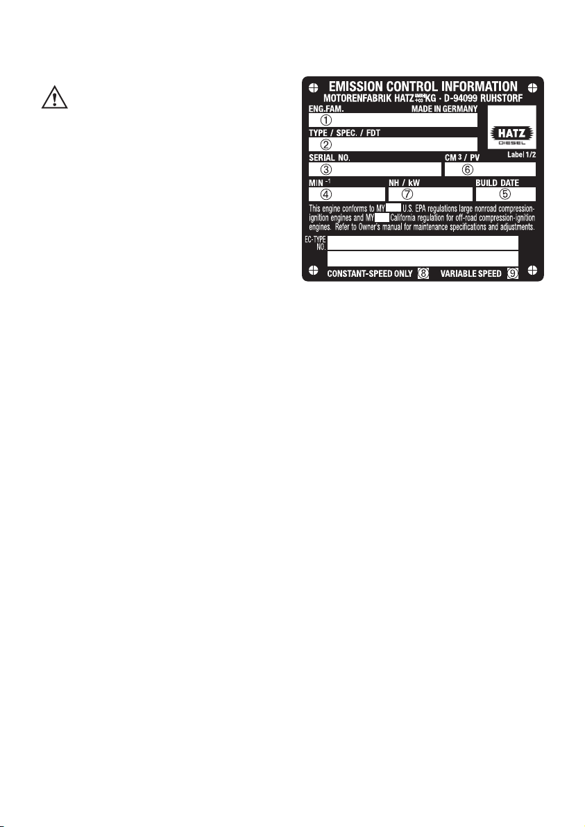
3.5. EPA/CARB-type plates and
fuel label
There are two EPA/CARB- type plates applied for
the identification of the engine. The type plates
are placed on the crankcase resp. on the capsule
(chapt. 2).
They include the following emission control information (Figure 5a):
Label 1/2
5a
➀ EPA/CARB-Engine Family Number
➁ engine type / spec. (only for special
equipment) /Fuel Delivery Timing
➂ engine number
➃ max. engine rated speed
➄ build date
➅ displacement
➆ rated power
➇ “constant speed only” (if requested)
➈ “variable speed” (if requested)
Every engine is equipped with an additional
loose engine type plate. If the original type
plate on the engine is not readily visible after
the engine is installed in the equipment then
the second loose type plate must be attached
on the equipment in such a manner that it is
readily visible to an average person.
10

For any offer as well as spare parts orders it is
necessary to mention the following data (also
see spare parts list, page 1):
➁ engine type / spec.
(only for special equipment)
➂ engine number
➃ max. engine rated speed
The layout is identical for constant-speed and
variable speed application.
Attention:
If the engine was certified for constant-speed
application and shall be used so, the field "constant-speed only" is marked with “X”.
If the engine was certified for variable speed application and shall be used so, the field "variable
speed" is marked with “X”.
Always install the engine for its intended application in order to comply with EPA and CARB
emission regulation requirements.
Label 2/2
5b
The engine must be operated with “LOW SULFUR FUEL OR ULTRA LOW SULFUR FUEL
ONLY”.
The label also states the applicable emissionrelated power category of the engine.
Fuel label
5c
The fuel label is placed nearby the fuel inlet.
If there was no fuel tank mounted to the engine,
the label has to be permanently attached to the
equipment near the fuel inlet.
3.6. EMISSION-RELATED
INSTALLATION INSTRUCTIONS
See supplemental information for EPA certified
engines, Page 47; resp. supplemental information for California regulations for off road
engines, Page 65.
11
LOW SULFUR FUEL OR ULTRA
LOW SULFUR FUEL ONLY
EMISSION CONTROL INFORMATION
LOW SULFUR FUEL OR
ULTRA LOW SULFUR FUEL ONLY
❏ < 8 kW / ❏ 8-19kW / ❏ 19-37kW /
❏ 37-56 kW PM Standard: 0.3 g/kWh
Power category:
Label 2/2
4. Operation
4.1. Before first start-up
Engines are normally delivered without any fuel
or oil.
4.1.1. Engine oil
Oil quality
Qualified are all trademark oils which fulfil at
least one of the following specifications:
ACEA – B2 / E2 or more significant
API – CD / CE / CF / CF-4 / CG-4 or more
significant.
If engine oils with low quality standard are being
used, the intervals of changing the engine oil
have to be reduced from 250 to 150 resp. 500 to
250 hours of operation, see chapter 5.1.
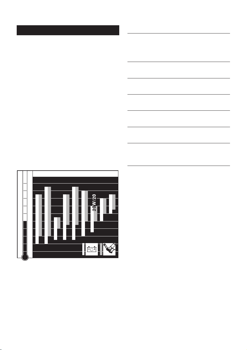
Oil viscosity
6
Choose a suitable oil viscosity according to the
ambient temperature when the engine is started
from cold (Figure 6).
-40
-30
-20
-10
0
10
20
30
40
50
104
86
68
50
32
14
-4
-22
-40
OIL: SAE...
°C°F
5W/30
5W/40
10 W / 4 0
10 W / 3 0
15 W / 4 0
30
40
122
10 W
Engine oil quantities and dipstick markings
dipstick
Engine type Sump
Oil content marking
(liter) (Figure 7,
item 2)
2L41C, 2 M41 Z
Yes 7.5 C
No 4.5 A
2M41
Yes 8.5 C
No 5.5 A
3L41C, 3 M41 Z
Yes 10.5 D
No 8.0 A
3M41
Yes 11.0 D
No 8.5 A
4L41C, 4L42C, Yes 13.0 D
4 M 41 Z No – –
Yes 14.0 D
4 M 41, 4 M 42
No – –
Note:
The engine oil contents stated here are to be
regarded as approximate.
In all cases, the MAX marking on the dipstick
should be complied with.
12
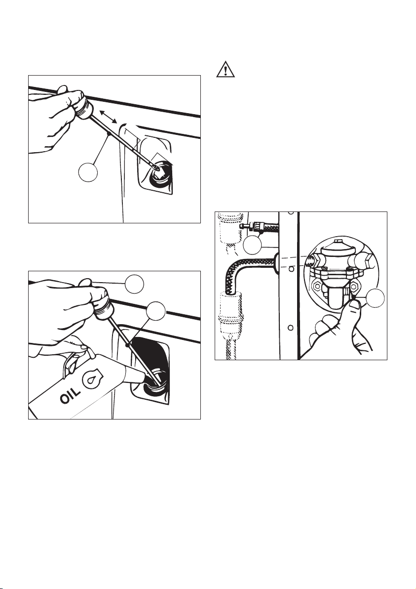
The engine should be in a horizontal position
before adding oil or checking the oil level.
7
– Pull out dipstick „1“ (fig. 7).
8
– Add engine oil up to the MAX mark on dipstick
„1“ (Figures 7 and 8).
– Run the engine for a short time, then check oil
level again and correct if necessary.
1
L3/45
A
2
1327/2
L3/47
MAX
MIN
1
4.1.2. Fuel
Stop the engine before refilling the
fuel tank. Never refuel near a naked
flame or sparks which could start a fire. Don’t
smoke. Use only pure fuel and clean filling
equipment. Take care not to spill fuel.
All diesel oils sold as fuel and complying with
the following minimum specifications can be
used:
EN 590 or
BS 2869 A1 / A2 or
ASTM D 975 - 1D / 2D
9
– Before the engine is first started, or if the fuel
system was run dry, prime the fuel delivery
pump at lever „1“ until fuel is heard to flow
back through the return line „2“ to the fuel
tank.
Important !
Remember to replace the access cover for the
fuel delivery pump in the side panel of the engine enclosure after priming the pump (Chap. 2).
L3/46
2
1
13
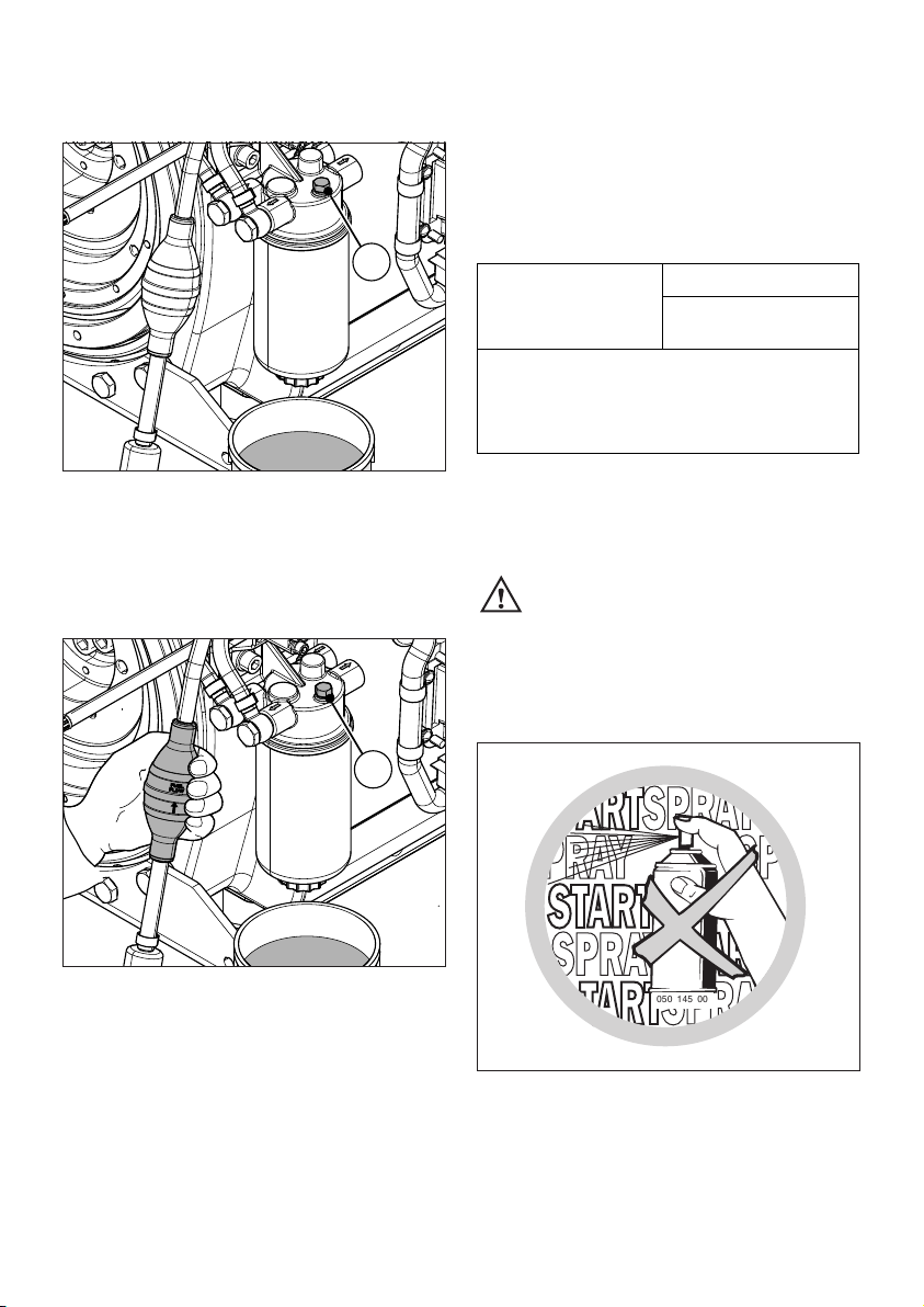
Models with manual fuel pump
(On 4L42C and 4M42 engines only)
10
– Place a suitable vessel under the filter to trap
escaping fuel.
– Open the vent screw 1 by approx. one turn.
11
– Compress and release rubber ball repeatedly,
until fuel escapes from the vent screw 1.
– Close vent screw 1, then actuate rubber ball
another two times.
1
1
Low temperature resistance
At low temperatures, the viscosity of Diesel fuel
increases. This may result in clogging of the fuel
system. Thus, winter fuel must be used at outside temperatures below 0 °C, or petroleum
must be added in time.
4.2. Starting
Do not run the engine in closed or
badly ventilated rooms – danger of
poisoning! Before the engine is started, always
make sure that nobody is in the danger area
(moving parts on engine or machinery) and
that all safety guards are in place.
12
Never use any spray starting aids
L3/250
050 145 00
Lowest ambient
temperature when
starting, in °C
Paraffin content for:
Summer Winter
fuel fuel
0 up to –10 20 % –
–10 up to –15 30 % –
–15 up to –20 50 % 20 %
–20 up to –30 – 50 %
14
If possible, disengage the engine from any
driven equipment.
The auxiliary equipment should always be placed
in neutral.
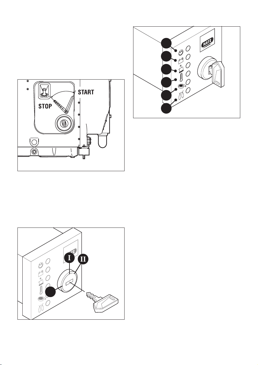
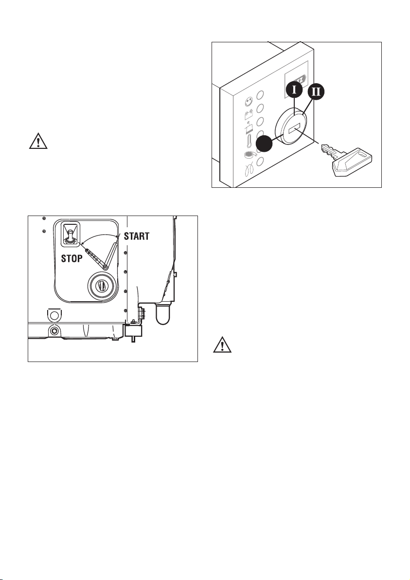
4.2.1. Starting with the electric starter
13
– Move the speed control lever to the 1/2 START
or max. START position, according to requirements and starting conditions.
Note that a lower speed setting will cause less
exhaust smoke when starting.
14
– Insert the key to its stop and turn it to
position I.
0
15
– Battery charge telltale „2“ and oil pressure
warning „3“ must light up.
– Turn start key to position II (Fig. 14).
– As soon as the engine runs, release the start
key. It must return to position I by itself and
remain in this position during operation.
The battery charge telltale and oil pressure
warning must go out immediately after starting. Indicator light „1“ is on when the engine is
in operation.
– The air cleaner maintenance indicator „5“ only
lights up during operation if the air cleaner element needs to be cleaned or renewed (Fig. 15,
see chapter 5.4.2.).
– The engine temperature display „4“ (additional
equipment) lights up if the temperature at the
cylinder head becomes too high.
Switch off the engine and trace and eliminate the cause of the problem, see chapter 7.
– Always turn the start key back to position 0
before re-starting the engine. The repeat lock
in the ignition lock prevents the starter motor
from engaging and possibly being damaged
while the engine is still running.
1
2
3
4
5
6
15
Important!
If a starter protection module is installed, the
start key has to be returned to position 0 for at
least 8 seconds after the engine has failed to
start or after switching it off before a further
attempt can be made to start the engine.
Preheating device with automatic heating
timer (additional equipment)
The preheating light „6“ lights up additionally at
temperatures below 0° Celsius (Fig. 15).
– After the light has gone out, start the engine
without delay.
Automatic shut-down function
(additional equipment)
This is characterized by a brief flashing of all
pilot lamps once the starter key has been turned
to position I, figure 15.
Important!
If the engine cuts out immediately after starting
or switches off by itself during operation, a
monitoring element in the automatic shutdown
system has tripped. The corresponding indicator
light (Fig. 15, positions 2 - 5) will come on.
After the engine has stopped, the display continues to glow for about 2 minutes.
The electrical device then switches itself off automatically. The display lights up again after the
start key has been turned back to position 0 and
then to position I again.
Trace and eliminate the cause of the operating
fault before trying to restart the engine (see
chapter 7).
The display light goes out when the engine is
next started.
Even with automatic shutdown monitoring the
oil level must be checked every 8 – 15 operating hours (Chapter 5.2.1.).
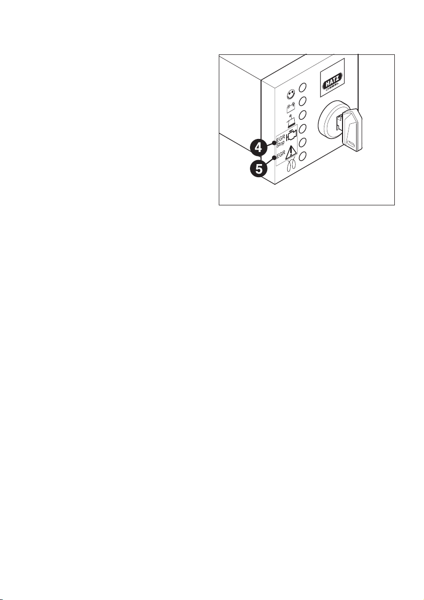
On 4L42C and 4M42 engines only
16
These engines are equipped with an exhaust gas
recirculation valve (EGR). This results in the following changes regarding the pilot lamps:
– The engine diagnosis indicator „4“ goes on as
soon as the cylinder head temperature exceeds
the admissible range.
Stop the engine and eliminate the cause as
described in Chapter 7.
– The pilot lamp „5“ flashes during operation
only if there is a problem in conjunction with
the exhaust gas recirculation system. This also
includes a contaminated air cleaner. This is indicated by the following flashing code of pilot
lamp „5“:
7 short flashes (approx. 0.5 seconds) and
1 long flash (approx. 1.5 seconds)
The flashing code indicates that the air cleaner
must be cleaned or replaced, chapter 5.4.2.
For troubleshooting regarding other flashing
codes, please contact immediately your nearest
HATZ service station.
Problems in the exhaust gas recirculation
system may impair the engine’s exhaust gas
values.
16
4.2.2. Emergency starting
If the engine has been stopped by the automatic
shutdown system because of an electrical fault
signal or inadequate oil pressure, an emergency
start can be attempted, though in this case the
manufacturer will accept no liability for consequential damage.
An emergency start could for example be unavoidable if the engine is used to power a vehicle which has come to a halt in a potentially
dangerous area (for example on a rail crossing
or road junction).
Proceed as follows:
– Detach the hood of enclosure „13“ (Figures 1
and 2) or side panel „2“ (Figures 3 and 4).
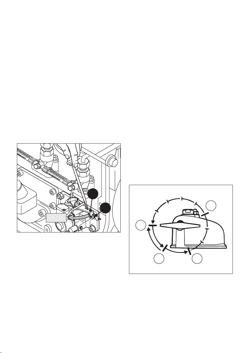
17
– Place a suitable tool, for example a screw driv-
er, behind emergency start lever „2“ and pull
sharply outwards. This will break the lead seal
„3“ between the emergency start lever and the
screw on the engine block.
– As soon as the emergency start lever is in the
starting position, the engine can be started
again.
3
2
START
Important:
If the emergency start lever is used, the automatic shutdown system ceases to operate and the
warranty is invalidated. For this reason, run the
engine only in a genuine emergency and for a
very short time (a few seconds) after operating
the emergency start lever. Make sure before restarting the engine that there is sufficient oil in
the engine; if oil pressure is too low, irreparable
engine damage may occur very quickly.
Immediately after running the engine in an emergency, locate the origin of the fault signal and
rectify the fault (see Chapter 7).
If any problems arise, please contact the nearest
HATZ service point.
4.2.3. Starting with handle
(on 2-4 M 41 engines only)
Preparations
– Move the speed control lever to START posi-
tion (Fig. 13).
18
– Turn all decompression levers (1 on two-cylin-
der engines, 3 on three-cylinder engines, 4 on
four-cylinder engines) to position 1.
L3/1
2
1
3
0
17
Important !
Turn decompression levers only in the direction
shown by the arrow.
Exception:
the lever can be moved back directly from position „1“ to „0“.
Never operate the automatic decompression system when the engine is
running.
– Check that the starting handle is in correct
working order, without a broken tubular handle
worn engagement dogs or similar faults.
– Lightly grease the sliding-contact area between
the starting handle and the guide sleeve.
19
– Insert the starting handle, hold it with both
hands and stand in the correct position in
relation to the engine.
– Turn the engine over until it is felt to move
more freely.
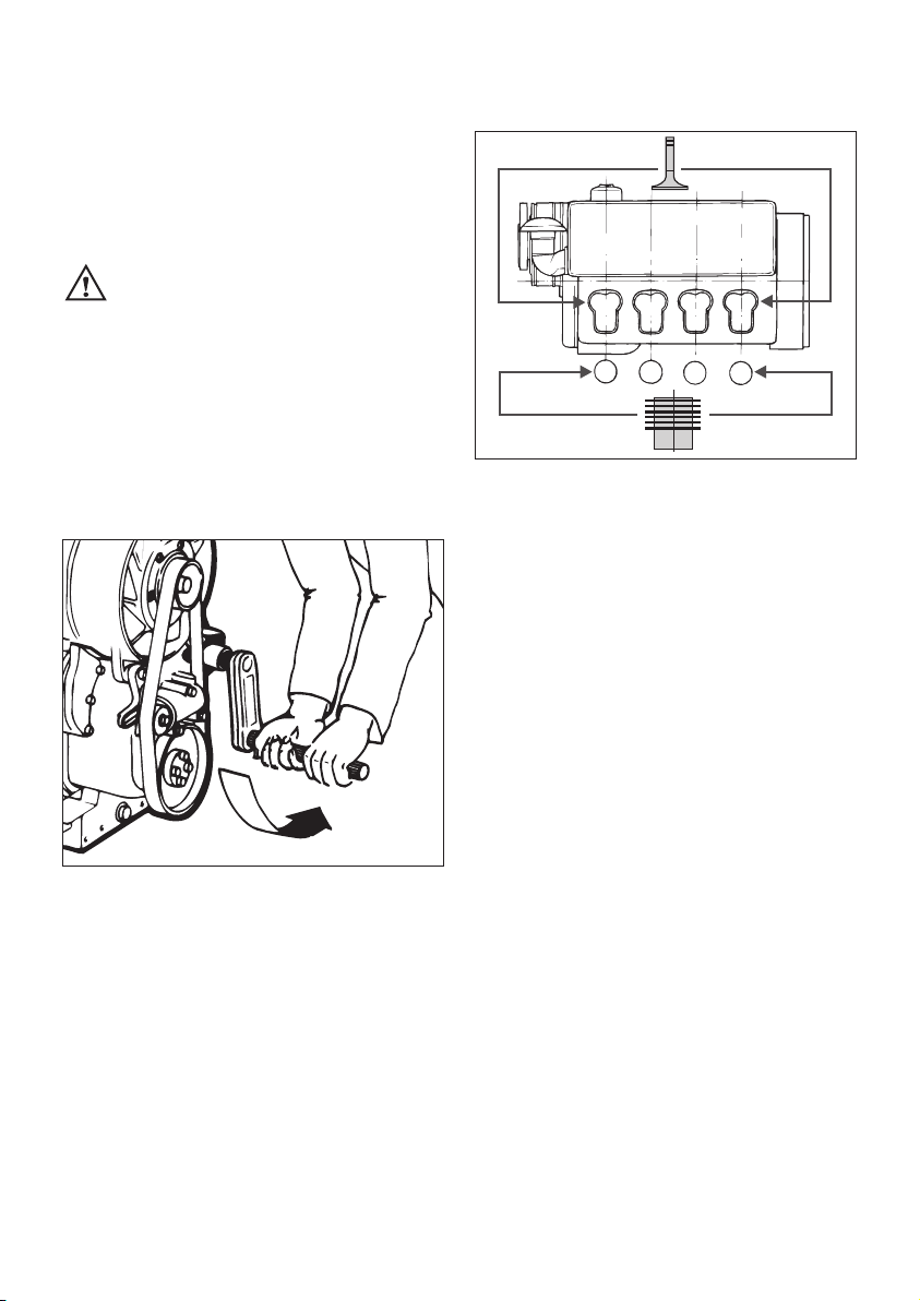
2M41 two-cylinder engines
– Turn the decompression lever to position „2“
(Figure 18).
L3/2
3M41 three-cylinder engines
20
– Turn the decompression levers for cylinders 1
and 3 (counting from the fan end) to position
„2“ (Figures 18 and 20).
– Turn the decompression lever for cylinder 2 to
position „3“.
4M41 four-cylinder engines
– Turn the decompression levers for cylinders 1,
3 and 4 (counting from the fan end) to position „2“ (Figures 18 and 20).
– Turn the decompression lever for cylinder 2 to
position „3“.
Starting procedure
– Turn the starting handle with both hands at an
increasing speed.
The maximum speed of rotation must have been
reached by the time the decompression lever
has returned to position „0“.
– As soon as the engine has started, pull the
starting handle out of the guide sleeve.
1
2
3
4
12 345678
L3/246
18
– If the engine backfires during starting because
it was not turned over with sufficient force (the
engine could even start to run backwards in
certain circumstances), release the starting
handle immediately and move the speed control lever to the STOP position (Chapt. 4.3.).
The starting handle could be driven
round by the engine and cause injury.
– Wait until the engine has come to a standstill
before repeating the preparatory procedure
and making another attempt to start it.
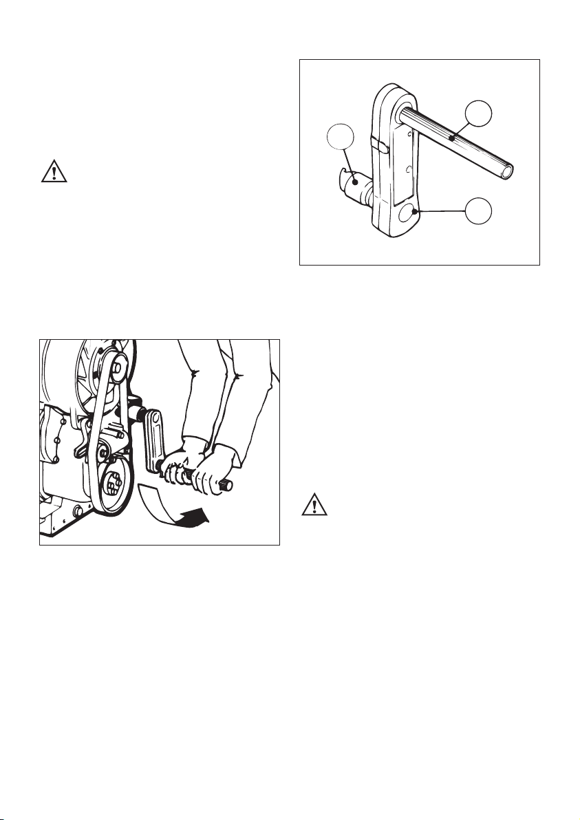
4.2.4. Starting with the handle with
kick-back damping
21
L3/2
22
– Preparations for starting the engine and the
hand starting procedure are precisely the
sameas with the standard handle.
Always hold tubular grip „1“ with both hands
(Figures 21 and 22).
– Turn the handle slowly at first, until the pawl
engages in the ratchet, then increase turning
force to build up speed. The highest speed
must have been reached by the time the decompression lever returns to position „0“.
As soon as the engine has started, pull the
starting handle out of the guide sleeve.
You must hold the tubular grip firmly
to maintain contact all the time between the starting handle and the engine.
Maintain turning force during the entire hand
starting operation.
– If backfiring should occur while hand starting
the engine too soft, the brief reversal of movement disengages the pawl between the crankshaft „2“ and the drive dog „3“ (Fig. 22).
– If backfiring occured and the engine starts
running backwards (smoke from airfilter),
release crankhandle immediately and move
speed control lever into STOP-position,
chapt. 4.3.
L3/3
1
2
3
19
– To repeat the starting attempt, wait for the en-
gine to cease rotating, reset the automatic decompression device and turn the starting
handle in the correct starting direction again.
4.3. Stopping the engine
If the engine is shut down for a short
period, or at the end of the working
day or shift, keep the key and the starting
handel in a safe place, out of reach of unauthorized persons.
Engines with electric starter
23
– Move the speed control lever to the stop posi-
tion; the engine will be shut down.
24
– Turn the starter key to the 0 position and pull
it out. The pilot lamp lights must then go out.
Note:
Engines with an automatic shut-down function
can also be switched off by turning the start key
back to position 0.
Engines with starting handle
– Move the speed control lever to the stop posi-
tion; the engine will be shut down (Picture 23).
Never stop the engine by moving the
decompression lever.
0
20

5. Maintenance
The engine must be stopped before any maintenance work is attempted.
Comply with legal requirements when handling and disposing of old oil, filters and
cleaning materials.
Keep the engine’s starting key out of reach of unauthorized persons.
Disconnect the negative battery terminal.
At the end of the maintenance work, check that all tools have been removed from the engine and
all safety guards, covers etc. replaced in their correct positions. Before starting the engine, make
sure that nobody is in the danger area (engine or driven machinery).
5.1. Maintenance summary
Maintenance intervals Maintenance work required Chap.
21
Every 8 – 15 hours of
operation, or before
each daily start-up
Every 250 hours
of operation
Every 500 hours
of operation
Every 1000 hours
of operation
Check oil level.
Check combustion air intake area.
Check the cooling air system
Engine oil change (2 M 41 without sump,
2...4 L 41 and 4 L 42 in general).
Clean fan, cooling fins and oil cooler.
Check tightness of threaded connections.
Cleaning of mesh insert in exhaust pipe.
Check water trap
Check for contamination of fuel pre-filter, renew if
necessary.*
Checking operation of air cleaner maintenance
indicator.
Do not tighten the cylinder head nuts.
Renew the fuel pre-filter.
Air cleaner maintenance.
Check and adjust valve clearances.
Engine oil change (2 M 41 with sump,
3...4 M 41 and 4 M 42 in general).
Renew the oilfilter.
Renew the fuel filter
5.2.1.
5.2.2.
5.2.3.
5.3.1.
5.3.2.
5.3.3.
5.3.4.
5.3.5.
5.4.1.
6.1.
5.4.1.
5.4.2.
5.4.3.
5.4.4.
5.4.5.
5.5.1.
8-15
250
500
1000
* Fuel pre-filter renewal intervals depend on the degree of fuel contamination, the care taken when
refuelling and the amount of contamination inside the fuel tank.
2 M 41 without oil pan
2 M 41 with oil pan; 3 - 4 M 41 in all cases
22
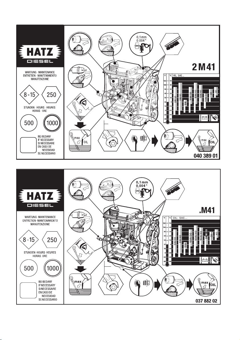
25
26

27
Depending on engine type and version, one of
the three self-adhesive maintenance charts illustrated here and on the previous page will be
supplied. It should be attached to the engine or
equipment at a point where it is clearly visible.
Comply with the maintenance intervals stated in
the maintenance summary in this chapter
The following work is essential on new or
reconditioned engines after the first 25 hours
of operation:
– Change the engine oil and renew the oil filter
element (Chapter 5.3.1. and 5.4.5.).
– Check valve clearances and adjust if neces-
sary(Chapter 5.4.3.).
– Check tightness of all screw connections
(Chapter 5.3.3.).
Do not take up slack at cylinder head bolts.
If the engine has not been operated for long
periods at a time, change the oil and renew the
filter element after a maximum of 12 months,
regardless of how many operating hours have
been recorded.
23
5.2 Maintenance every 8 – 15 hours
of operation
5.2.1. Check engine oil level
When checking the oil level, the engine should
be standing level, and must not be running.
28
– Check oil level at the dipstick. Add oil up to
the MAX mark on dipstick „1“ if necessary
(Chapter 4.1.1.).
5.2.2. Check combustion air intake area
Severe contamination is a sign that the air contains a high level of dust, and that the maintenance intervals should be shortened accordingly
(Chapter 5.4.2.).
1327/2
L3/47
MAX
MIN
1
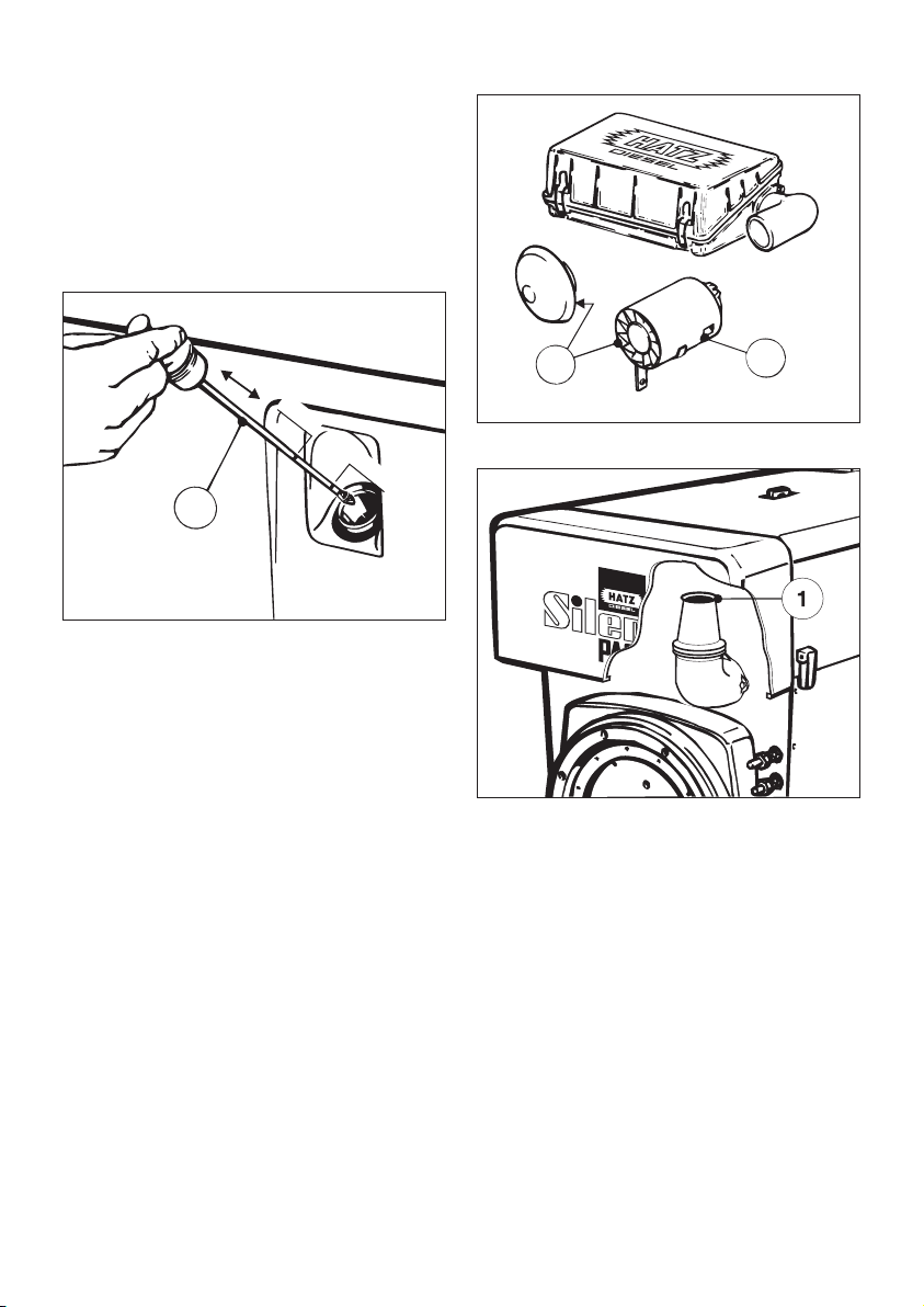
29
30
– Inspect intake opening „1“ on the rain protec-
tion cap or cyclone separator for severe blockage with dirt, for instance leaves, heavy dust
deposits etc., and clean if necessary.
(Figures 29 and 30).
– Check for free airflow at dust outlet hole „2“
on the underside of the housing, and clean if
necessary (Picture 29).
With oily contamination remove cyclone and
clean it.
1
2
L3/63
24
 Loading...