

Hatz Diesel 2-4L30, H2-3L30, 2-4L41, 2-4L31, 2-4M31 Workshop Manual
...
Workshop manual
2-4L30.
H2-3L30.
2-4L31.
2-4L40.
2-4L41.
2-4M31.
2-4M40.
2-4M41.
438 402 00 - 1.97 - 0.4 Printed in Germany


Introduction
1. General
Illustrations of engine
Type plate data
Lubricating oil circuit
Technical data
Sealants and adhesives
Special tools and
Workshop equipment
2. Additional equipment
A 01.00 Fuel
A 01.40 Delivery pump
with hand pump
A 03.00 Exhaust
A 03.12 Detaching and attaching
enclosure for silencer
(muffler)
A 04.00 Mechanical starting
A 04.10 Crank handle
A 04.20 Automatic decompressor
A 04.70 Engine rotating device
A 04.80 Start release
A 05.00 Electric starting
A 05.40 Alternator
A 07.00 Lubricating oil
A 07.10 Lubricating oil cooler,
air cooling
A 07.11 Lubricating oil cooler,
water cooling.
A 11.00 Automatic mechanisms
A 11.70 Temperature-controlled
starting fuel volume
regulator
A 15.00 Housing
A 15.20 Connecting housing
A 30.00 Liquid cooling
A 30.20 Water pump
A 30.40 Thermostat
Contents

3. Basic engine equipment
M 01.00 Crankshaft
M 01.10 Balancing weights 2L / 3L
M 01.20 Balancing weights, 4L
M 01.30 Cleaning crankcase,
installing injector nozzles
M 02.00 Crankshaft
M 04.00 Camshaft
M 04.10 Camshaft for valve timing
M 04.20 Camshaft for injection pump
M 04.30 Governor and injection timer
M 05.00 Conrod
M 06.00 Piston and cylinder
M 06.10 Air-cooled engines
M 06.20 Water-cooled engines
M 07.00 Cylinder head
M 07.10 Air-cooled engines
M 07.20 Cylinder head repairs
(air-cooled engines)
M 07.30 Water-cooled engines
M 07.40 Cylinder head repairs
(water-cooled engines)
M 10.00 Oil pump
M 11.00 Timing case cover
M 12.00 Starting charge
M 12.10 with injection pump
PFR 1K 80
M 12.20 with injection pump
PFR 1K 90
M 12.30 with injection pump
PFR 1K 90
from serial No. L/M31.12,
M40.16, 2L40.19, 3-4L40.18
and L/M41
M 13.00 Fan
M 14.00 Fuel injection equipment
M 14.00 Injection pump, functional test
M 14.10 with injection pump
PFR 1K 80
M 14.20 with injection pump
PFR 1K 90
M 14.30 Injector
M 14.40 Injector nozzle
M 14.50 Adjusting work with
injection pump PFR 1K 80
M 14.60 Adjusting work with injection
pump PFR 1K 90
M 17.00 Flywheel
M 20.00 Engine shutdown device,
belt tensioner
M 22.00 Air cleaner
M 31.00 Crankcase breather
M 32.00 Speed control
M 32.10 with injection pump
PFR 1K 80
M 32.20 with injection pump
PFR 1K 90
M 35.00 Enclosure
4. Tables
Tightening torques
Repair data
Fuel injection equipment and
adjusting values
Governors
Lubricating oil contents and dipstick
Key to circuit diagrams
HATZ wiring identification
Circuit diagrams
Trouble-shooting table for the
electrical system
Contents

Introduction
This workshop manual is in accordance with the technical status shown on each page
(month / year). It has been compiled in such a way that a trained mechanic can perform
all repair work correctly. Instructions such as „Clean parts“ etc. have been omitted, as
they are assumed to be self-evident.
All work must be carried out only with the specified tools or with others of absolutely
equivalent quality.
It is assumed that the normal hand tools will be available, even if not called for specifically in this manual.
Please refer to the operating manual for details of routine maintenance work, operating
fluids and materials, troubleshooting etc.
Use only genuine HATZ spare parts in repair work.
Comply also with generally or locally valid legislation and with the instructions issued by
trade associations or accident insurers.
The details provided here may differ if special equipment is installed. Please appreciate
that neither the workshop manual nor the spare parts list can take all such deviations
into account. If problems occur, please contact the nearest HATZ service point.


1
L / M . . 10.98
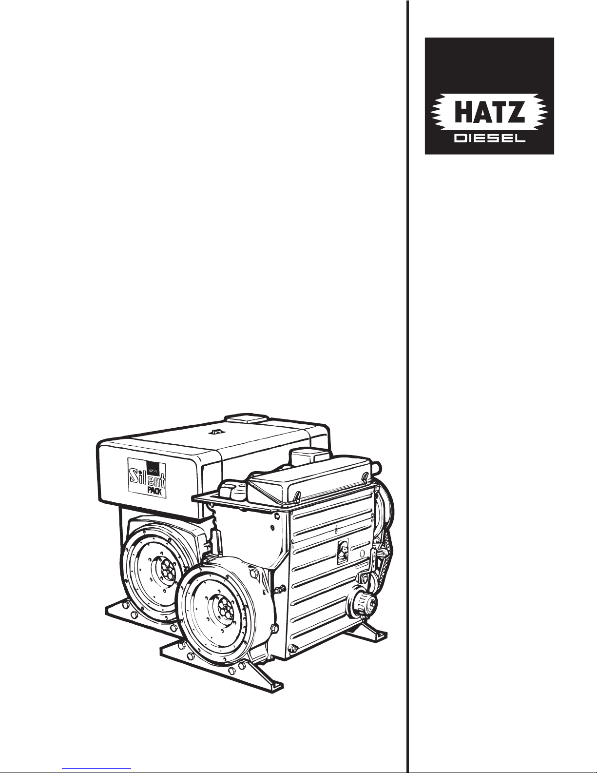
1. General
Service and flywheel side
Governor and exhaust side
1
L / M . . 10.98
Starter and flywheel side
Engines: 2 - 4 L . . S / Z
1 Lub.-oil filling and dipstick
2 Speed control lever
3 Exhaust silencer
4 Oil drain plug
5 Lub.-oil filter
6 Engine cover
7 Side panel
8 Cooling fan with built-in alternator
9 Cooling fan drive belt
10 Hydraulic belt tensioner
11 Stop device
12 Governor housing
13 Cooling air duct for lub.-oil cooler
21 Cyclone-type pre-cleaner
22 Eye hook for transport, disappearing
max. load 500 kg
23 Access to fuel feed pump
24 Starter motor
25 Fuel feed line
26 Fuel return line
27 Belt pulley with 1/2“ internal square
for cranking engine
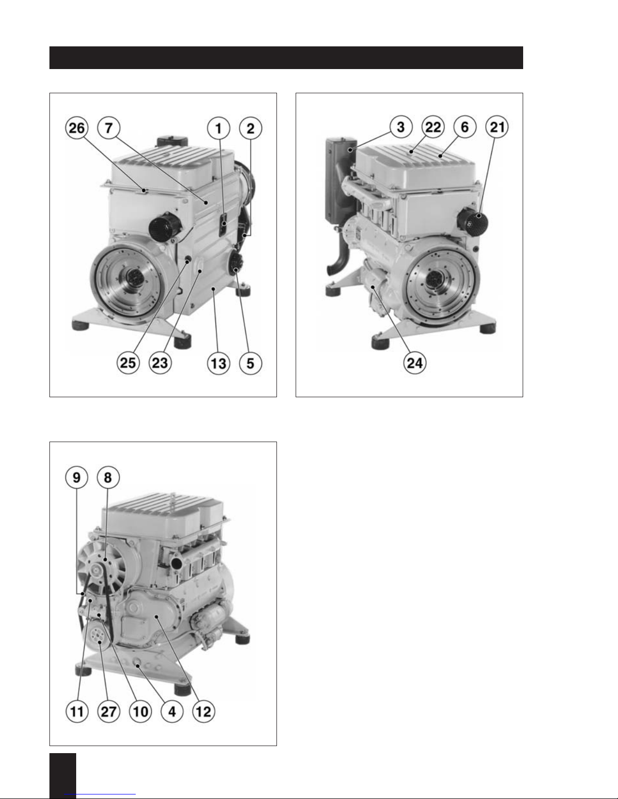
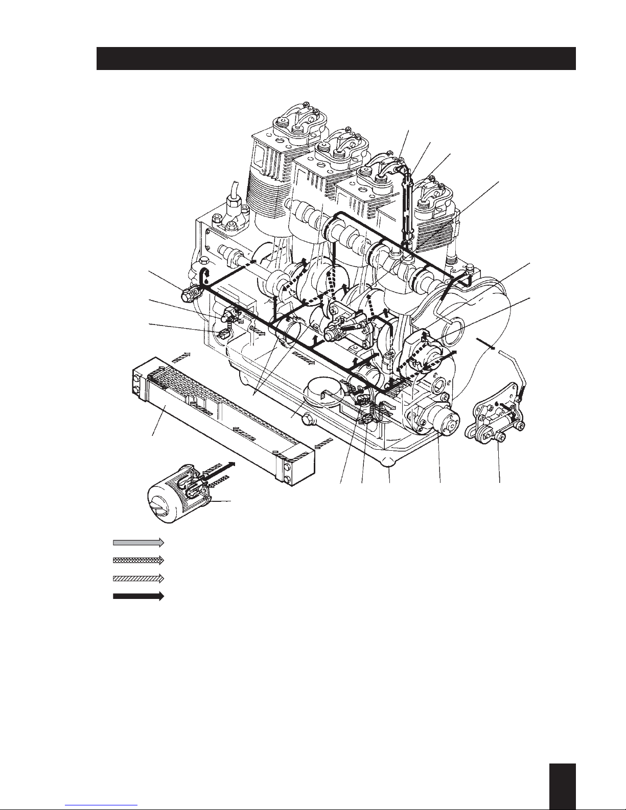
Engine illustrations

Operating and flywheel side
Encapsulated design
1 Lub.-oil filling and dipstick
2 Speed control lever
4 Oil drain plug
5 Lub.-oil filter
6 Batter y + terminal
7 Batter y - terminal
8 Wiring harness
9 Type plate
10 Fuel feed line
11 Fuel return line
14 Cover for capsule
15 Air intake duct of capsule
16 Outgoing air duct
17 Exhaust silencer (encapsulated)
20 Cover for air duct housing
(Access to governor housing of engine)
22 Eye hook for transport, disappearing
max. load 500 kg
23 Engine brackets
24 Access to fuel feed pump
25 Engine flange
26 Side panel
27 Cover, service side
28 Cover, outgoing air side
Operating and governor side
Outgoing air and flywheel side
Engine illustrations
1
L / M . . 10.98
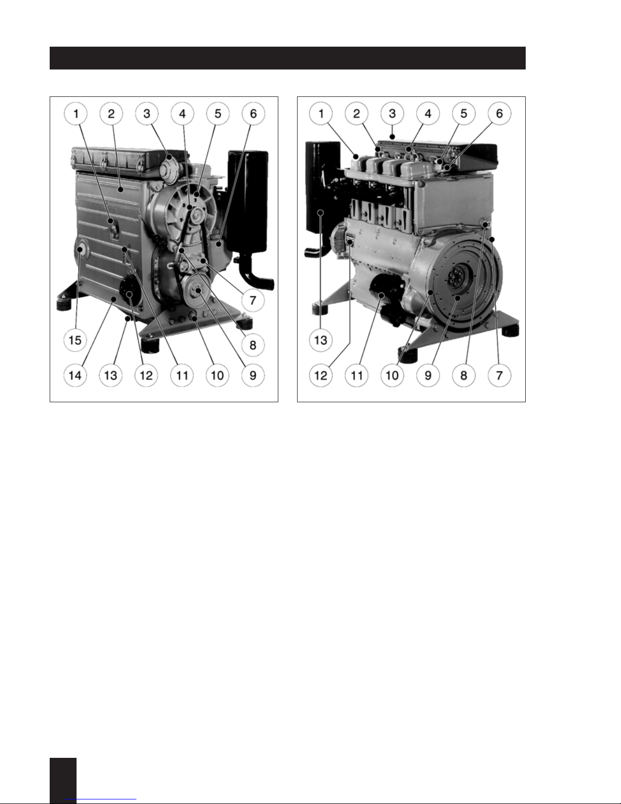
Operating side
Engine: 2 ... 4 M 31,
2 ... 4 M 40,
2 ... 4 M 41
1 Lub.-oil filling and dipstick
2 Side panel
3 Rain protection cap
4 Cooling fan drive belt
5 Cooling fan with built-in alternator
6 Governor housing
7 Hydraulic belt tensioner
8 Stop device
9 Belt pulley with 1/2“ internal square for
cranking engine
10 Oil drain plug
11 Speed control lever
12 Lub.-oil filter
13 Oil drain plug (oil sump)
14 Cooling air duct for lub.-oil cooler
15 Access to fuel feed pump
1
L / M . . 10.98
Flywheel side
Engine: 2 ... 4 M 31,
2 ... 4 M 40,
2 ... 4 M 41
1 Cylinder head cover
2 Fuel pressure pipe
3 Cover for air filter(s)
4 Eye hook for transport, max. load 500 kg
5 Injector
6 Fuel return line
7 Fuel feed line
8 Wiring harness duct
9 Flywheel
10 Engine flange
11 Starter motor
12 Type plate
13 Exhaust silencer
Engine illustrations
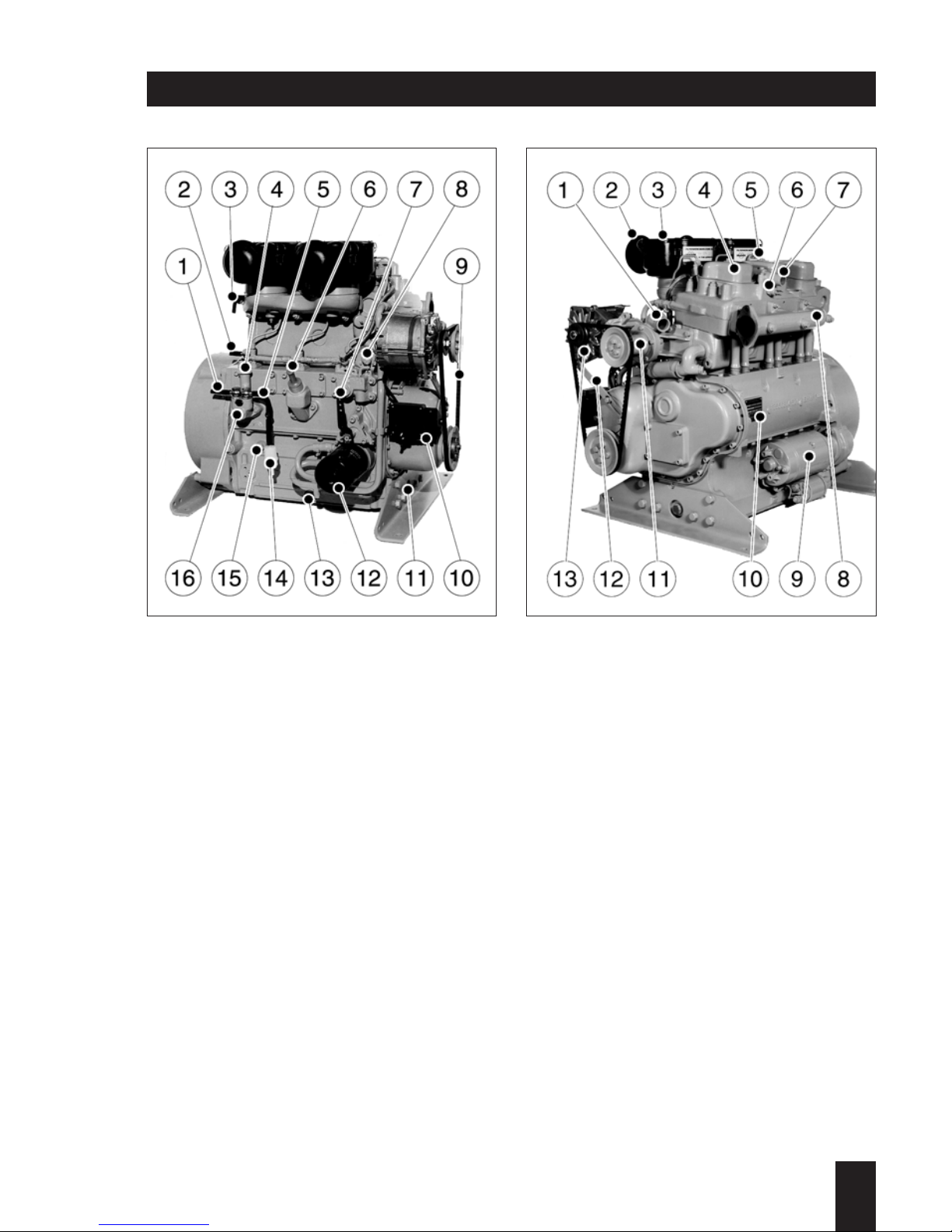
Operating side
Engine: H 2 L 30,
H 3 L 30
1 Fuel line (feed pump - filter)
2 Fuel line (filter - injector pumps)
3 Hose connection
(Maintenance indicator for air filter)
4 Primer pump
5 Fuel feed line
(Fuel tank - fuel feed pump)
6 Lub.-oil filling and dipstick
7 Speed control lever
8 Solenoid, engine stop
9 V-belt
10 Voltage regulator
11 Oil drain plug, governor side
12 Lub.-oil filter
13 Oil drain plug,
14 Fuel pre-filter
15 Oil pressure switch
16 Fuel feed pump (Bosch)
Governor- and exhaust side
Engine: H 2 L 30,
H 3 L 30
1 Cooling water inlet
2 Rain protection cap
3 Air filter
4 Cylinder head cover
5 Fuel pressure pipe
6 Temperature switch
7 Cooling water outlet
8 Exhaust manifold
9 Starter motor
10 Type plate
11 Centrifugal pump
12 Belt-adjustment link
13 Alternator
IMPORTANT !
The standard transport suspension enables
safe transportation of the engine including
supplementary equipments, and is designed
for a maximum load of 500 kg (1100 lbs).
It is neither suitable nor approved to lift
complete units.
Engine illustrations
1
L / M . . 10.98

1
L / M . . 10.98
Type plate data
Complete type description
e.g.
Engine type
Engine version
2L40 C
Customer spec. list No. 1)
Customer-specification
Output in kW 2)
Execution code 2)
Adjustment instruction 1)
Special adjustm. regarding
engine speed, power output etc.
Injection pump delivery lift in mm
to obtain the required engine output.
Governor rod travel for adjusting the
correct fuel quantity in 1/100 mm
Engine number
Type-No.
064 10 81 031814
MOTORENFABRIK HATZ KG
D-94099 RUHSTORF
GMBH
CO
+
TYP KENNZ.
MOTOR / FABRIK NO.
ABE /AUSF.
MIN NH PV CM
MADE IN GERMANY
-1
3
Displacement in cm
3
3000 / 60
Engine speed
e.g.
Nominal speed
Speed increased under
no-load condition
max. no-load speed
1) If required
2) in special cases only; e.g. engines acc. to Federal Authority for Automobilism
Engine series no.:
The serial no. begins
with 10 and changes
continously (11,12) if
any major changes are
carried out.
Year of production
Fabrication-No. (continous)
3000 + 60 = 3060 min
-1
1 Rockers
2 Pushrods
3 Pushrod tubes
4 Hydr. starting charge device or
oil servo
5 Crankshaft
6 Main bearings
7 Hydraulic belt tensioner
8 Lubricating oil pump
9 Sump
10 Plug
– on engines without oil cooler
11 Threaded rod
– on engines with oil cooler
12 Oil suction strainer
13 Balancing shaft(s)
14 Lub. oil filter with bypass valve
15 Oil cooler
16 Oil pressure switch
17 Oil pressure relief valve
Lubricating oil circuit
1
L / M . . 10.98
1
2
3
4
5
6
7
8
910
11
12
13
14
15
10
16
17
Suction line
Oil pressure feed to filter on engines without oil cooler
Oil pressure feed to filter on engines with oil cooler
Oil circuit after oil cooler

Type 2L30 H2L30 3L30 H3L30 4L30
Operating cycle 4-stroke
Combustion system Direct injection
Number of cylinders 2 3 4
Bore / stroke mm 95 / 100
Displacement cm
3
1416 2124 2832
Compression ratio 18:1
Firing order, cyl.1:timing end 2-1 1-3-2 1-3-4-2
Direction of rotation anti-clockwise (looking at flywheel)
Cooling air requirement at
n = 3000 rpm m3/min 25 - 35 - 45
Combustion air requirement
at n = 3000 rpm m3/min 2.1 3.2 4.2
Net weight approx. kg
L 30 S 223 222 255 271 291
L 30 Z 228 228 262 279 306
L 30 C / K 276 - 331 - 396/386
Lubricating oil pressure at n = 800 rpm min.: 0.9 bar
Lubricating oil consumption max.: 1 % of fuel consumption, at full load
Starter motor 12 V, 2,7 kW or 24 V, 4,0 kW
Alternator 14 V, 50 A or 28 V, 40 A*
Battery 12 V, 88 / 143 Ah or 24 V, 55 / 110 Ah
Max. continuous inclination with and without with without only with
towards oil sump oil sump oil sump
Operating side 30° 30° 25° 25°
Flywheel side 30° 22° 25° 18°
Air outlet/starter side 30° 30° 30° 30°
Governor side 30° 25° 25° 15°
* At H 2 L 30 and H 3 L 30: 14 V, 33 A or 28 V, 27 A
1
L / M . . 10.98
Technical data L 30

1
L / M . . 10.98
Type 2L31 2L40 3L31 3L40 4L31 4L40
2M31 2M40 3M31 3M40 4M31 4M40
Operating cycle 4-stroke
Combustion system Direct injection
Number of cylinders 2 3 4
Bore / stroke mm 102/90 102/105 102/90 102/105 102/90 102/105
Displacemen cm
3
1470 1716 2205 2574 2940 3432
Compression ratio 18:1
Firing order, cyl.1: timing end 2-1 1-3-2 1-3-4-2
Direction of rotation anti-clockwise (looking at flywheel)
Kühlluftbedarf bei
n = 3000 min-1m3/min 25 29 35 39 46 49
Combustion air requirement
at n = 3000 rpm m3/min 2.1 2.6 3.2 3.9 4.2 5.2
Net weight approx. kg
L 31 S, L 40 S, M 40 223 255 291
L 31 Z, L 40 Z, M 40 Z 228 262 306
L 31 C / K, L 40 C / K 276 331 396/386
Lubricating oil pressure at n = 800 rpm min.: 0,9 bar
Lubricating oil consumption max.: 1 % of fuel consumption, at full load
Starter motor 12 V, 2,7 kW or 24 V, 4,0 kW
Alternator 14 V, 50 A or 28 V, 40 A
Battery 12 V, 88 / 143 Ah or 24 V, 55 / 110 Ah
Max. continuous inclination with and without with without only with
towards oil sump oil sump oil sump
Operating side 30° 30° 25° 25°
Flywheel side 30° 22° 25° 18°
Air outlet/starter side 30° 30° 30° 30°
Governor side 30° 25° 25° 15°
Technical data L 31, M 31, L 40, M 40

1
L / M . . 10.98
Type 2L41 3L41 4L41
2M41 3M41 4M41
Operating cycle 4-stroke
Combustion Direct injection
Number of cylinders 2 3 4
Bore / stroke mm 102/105 102/105 102/105
Displacement cm
3
1716 2574 3432
Compression ratio 18,7:1
Firing order, cyl.1:timing end 2-1 1-3-2 1-3-4-2
Direction of rotation anti-clockwise (looking at flywheel)
Cooling air requirement at
n = 3000 rpm m3/min 29 39 49
Combustion air requirement
at n = 3000 rpm m3/min 1,9 2,9 3,9
Net weight approx. kg
M 41 S 223 255 291
M 41 Z 228 262 306
L 41 C / K 276 331 396/386
Lubricating oil pressure at n = 800 rpm min.: 0,9 bar
Lubricating oil consumption max.: 0,2 % of fuel consumption, at full load
Starter motor 12 V, 2.7 kW or 24 V, 4.0 kW
Alternator 14 V, 50 A or 28 V, 40 A
Battery 12 V, 88 / 143 Ah or 24 V, 55 / 110 Ah
Max. continuous inclination with and without with without only with
towards oil sump oil sump oil sump
Operating side 30° 30° 25° 25°
Flywheel side 30° 22° 25° 18°
Air outlet/starter side 30° 30° 30° 30°
Governor side 30° 25° 25° 15°
Technical data L 41, M 41

Sealants and adhesives
Sealants and adhesives:
Code letters in the text and drawings refer to the products stated below. The same
details appear in our spare part lists.
A = 502 230 01 Loctite Activator 500 ml
B = 502 231 00 Loctite 573 50 ml
C = 502 232 00 Loctite 601 50 ml
D = 502 233 00 Loctite 221 50 ml
E = 502 234 00 Loctite 648 10 ml
F = 502 238 00 Technicoll 8058 750 g
+ 502 239 00 Technicoll 8367 750 g
G = 502 565 01 Loctite IS 407 20 g
H = 502 825 01 Silicon 30 ml
J = 502 830 02 High-temp. paste 1000 g
K = 503 426 00 High-temp. paste 100 g
L = 502 566 00 Silicon 100 g
1
L / M . . 10.98

1
L / M . . 10.98
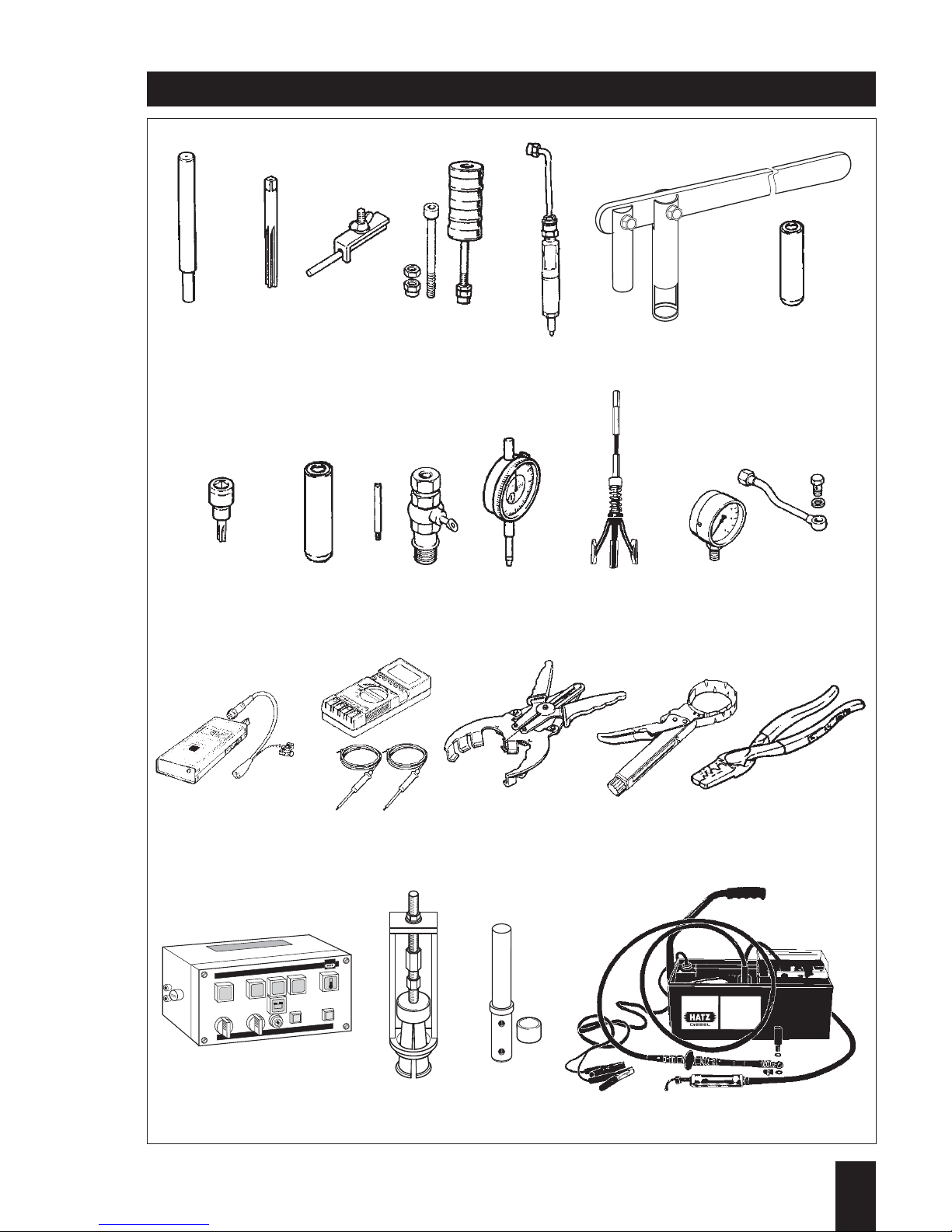
Special tools and workshop equipment
Series L / M engines
No. Ident-Nr. Code
Item
1
2
3
4
5
6
7
8
9
10
11
12
13
14
15
16
17
18
19
20
21
22
669 350 00
612 110 00
668 383 00
626 753 91
630 094 00
629 223 01
625 739 00
612 092 00
665 418 00
665 030 91
612 087 00
634 142 00
620 926 01
624 838 91
625 383 02
612 090 01
626 383 00
624 845 01
633 178 00
631 191 00
631 203 00
632 913 00
03.1.1
03.1.2
01.1.2
03.1.1
03.1.2
03.1.2
03.2.1
03.1.2
05.2.1
05.1.1
05.1.2
03.1.2
03.1.1
03.1.2
03.1.2
03.1.2
03.1.2
03.2.2
06.2.1
06.1.2
06.1.2
05.1.1
Pressing-in drift ∅ 9 mm for valve guides
Reamer 9 H 6 for valve guide
Clamp for fuel line
Impact extractor with accessories
Test nozzle 400 bar
Valve lifting tool
Pressing-in drift for valve stem seal
6 mm intl. hex. insert with centering pin
Driver sleeve for camshaft bearings
Overflow device for injection pump
Dial gauge – 1/100 mm
Honing tool
Oil pressure gauge 0 -6 6 bar with flexible tube
Rev. meter for fuel pressure pipe
Digital multimeter
Piston ring pliers
Piston ring clamping tool ∅ 70 - 100 mm
Crimping pliers up to 6 mm
2
Relay test box
Puller for belt tensioner bushings
Installation drift for belt tensioner bushings
High-pressure pump cpl.
Special tools and workshop equipment
1
L / M . . 10.98
12345 67
89101112 13
14 15 16 17 18
19 20 21 22
Injection - pump
timing set
A
B
E
C
D
R
e
l
a
is
-
F
u
n
k
t
i
o
n
s
-
u
n
d
Te
s
t
b
o
x
1
5
8
6
8
7
8
7a
5
0
–
+

Special tools and workshop equipment
Series L / M engines
Explanation of classification:
Example: 03. 1. 2
Manufacturer: 1 . . . Only available from HATZ
2 . . . Same item (or equivalent in function)
available commercialy
Necessity: 1 . . . Absolutely essential
2 . . . Useful or convenient
Type of repair: 01. . . Maintenance
02. . . Emergency repair
03. . . Repair in upper and external areas
05. . . Repair in area of driving gear
mechanism
5Q. . . General overhaul
(including all the necessary tests)
06. . . Component repairs
1
L / M . . 10.98
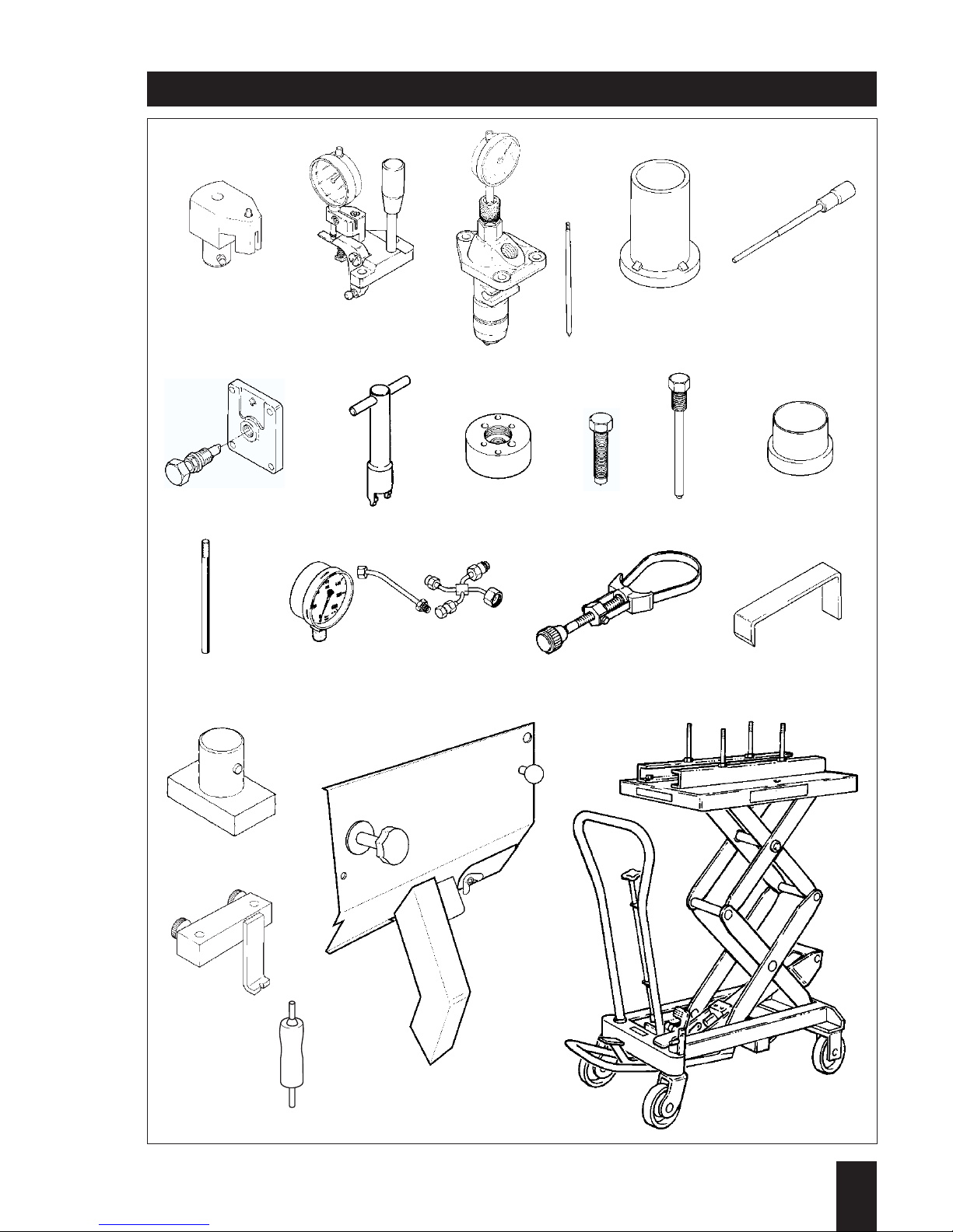
No. Ident-Nr.
Code
Item
23
24
25
26
27
28
29
30
31
32
33
34
35
36
37
38
39
40
41
42
43
44
45
46
47
624 340 01
624 346 01
624 347 00
624 348 01
624 349 00
624 350 00
606 000 00
618 140 01
618 418 00
610 390 00
620 300 00
624 393 00
621 056 00
626 211 00
604 628 00
620 307 01
620 638 01
619 746 00
630 439 00
619 852 02
619 854 02
619 855 02
624 863 02
624 864 01
629 055 00
05.1.1
05.1.1
05.1.1
05.1.1
05.1.1
05.1.1
05.1.1
03.1.1
03.1.1
03.1.1
03.1.1
05.1.1
03.1.1
03.1.1
03.1.1
01.1.2
02.1.1
05.1.1
05.2.1
5Q.1.1
5Q.1.1
5Q.1.1
03.2.1
03.2.1
02.1.2
Marking device for radial position of injection pump
Gauge for measuring governor rod travel
Gauge for adjusting start of fuel injection
Calibrating device for tool - 25 Locating pin for governor rod
Fuel injection volume adjusting tool
Wrench for starting charge adjustment
(mechanical system only)
Multipurpose puller in connection with tool - 31 Forcing-off screw for tool - 30 Forcing-off screw for centrifugal clutch
Forcing-off screw for centrifugal belt pulley
Assembly sleeve
M 10 x 1 guide pin for conrod
M 11 x 1 guide pin for conrod
Test pressure gauge for fuel injection system
Strap wrench
Locking device for tensioning roller
Holder for injection timer assembly
Gauge for oil spray nozzles
Air guide plate for 2 L / M
Air guide plate for 3 L / M
Air guide plate for 4 L / M
Elevating table, mobile
Adapter elements for - 45 Disassembly tools for cable plug
Special tools and workshop equipment
1
L / M . . 10.98
23 24 25 26 27
28 29 30 31 32 / 33 34
35/36 37 38 39
40
44
47
42
43
44
46
45


2
L / M . . 09.96
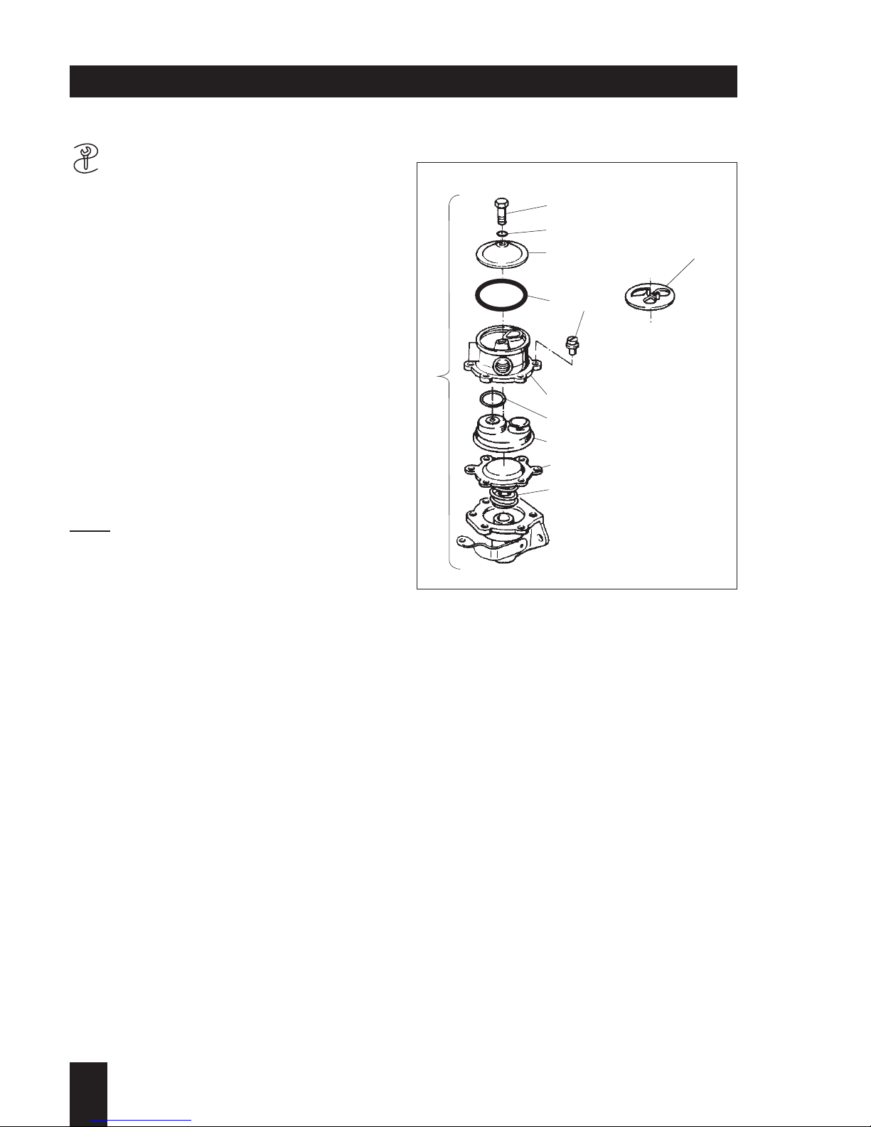
2. Additional equipment
- 3 -
General:
– When installing the fuel delivery pump,
make sure that the delivery and suction
lines are connected correctly.
Dismantling:
– Disconnect fuel feed line with clamp - 3 -.
– Separate the fuel lines from the delivery
pump.
– Unscrew and remove nuts with spring
washers, and take off fuel delivery
pump with O-ring.
– Dismantle fuel delivery pump 1 in the
numerical order of parts illustrated
(Fig. 182).
Note:
Since September 1992 fuel strainer 12
has been replaced by O-ring 5.
Because of this, an input-side fuel filter
must always be used.
This input-side filter is supplied as a spare
part with the fuel delivery pump and also
with the repair kit for the fuel delivery
pump.
Assembling:
Assemble by following the instructions in
the reverse order as appropriate.
2
L / M . . 09.96
182
A 01.00 Fuel
A 01.40 Fuel delivery pump
2
3
4
56
7
8
9
10
11
1
12
–
Preparations:
– Remove the hood from the enclosure
and air outlet duct; see M 35.00.
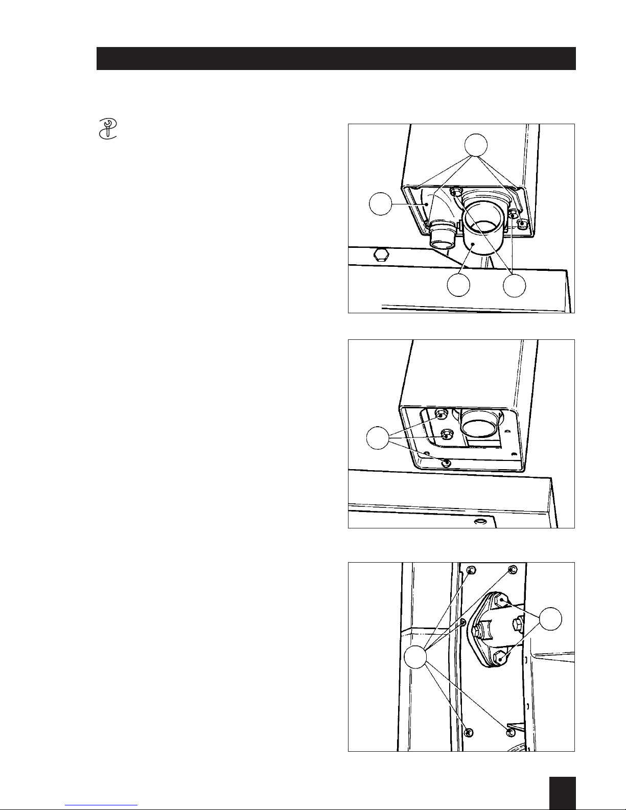
Detaching:
– Take out hex bolts (184/1) and detach
the connecting stub pipe with exhaust
pipe (184/2).
On more recent versions, the exhaust
pipe is secured with a clip.
– Take out the machine screws (184/3)
and remove the connecting cover
(184/4).
– Unscrew and remove the hex bolts
(185/1).
– Remove the machine screws (186/1)
and bolts (186/2).
2
L / M . . 09.96
184
185
186
A 03.00 Exhausts
A 03.12 Removing and installing the silencer (muffler)
enclosure(L 30, L 31, L 40, C/K)
L3 / 228
1
3
4
2
L3 / 229
1
L3 / 230
1
2

Lift off the enclosure with exhaust silencer
(muffler); see Fig. 187.
Note:
In some cases a spacing plate is installed
between the silencer enclosure and the
air duct housing.
– On the 2 - 3 L 40 from date of manufac-
ture 5.85 on, 4 L 40 from 1.86 on and L
31, the connecting stub pipe (189/1),
sealing washer (189/2) and plate
(189/3) are deleted.
Five sealing washers are installed
between the silencer and the exhaust
manifold.
– Pull the upper and lower sections of the
enclosure apart and lift out the silencer;
see Fig. 188.
Check the parts:
– Examine the enclosure sections and the
silencer for fractured welds or tapped
holes which are unfit for further use.
Installing:
– Install by following the removal instruc-
tions in the reverse order as
appropriate.
The silencer must be installed without
trapped stresses (a two-piece holder for
the silencer has been installed since
March 1989).
Note:
Before installing the connecting stub pipe
(189/1), check free movement of the sealing washer (189/2).
Place the sealing washer in the connecting stub pipe and install the plate (189/3).
It should be possible to move the sealing
washer radially. Next, place the sealing
washer on the silencer. Radial play must
not exceed 0.1 mm. If necessary, renew
the sealing washer.
2
L / M . . 09.96
187
188
189
L3 / 231
L3 / 232
L3 / 233
12
3
–
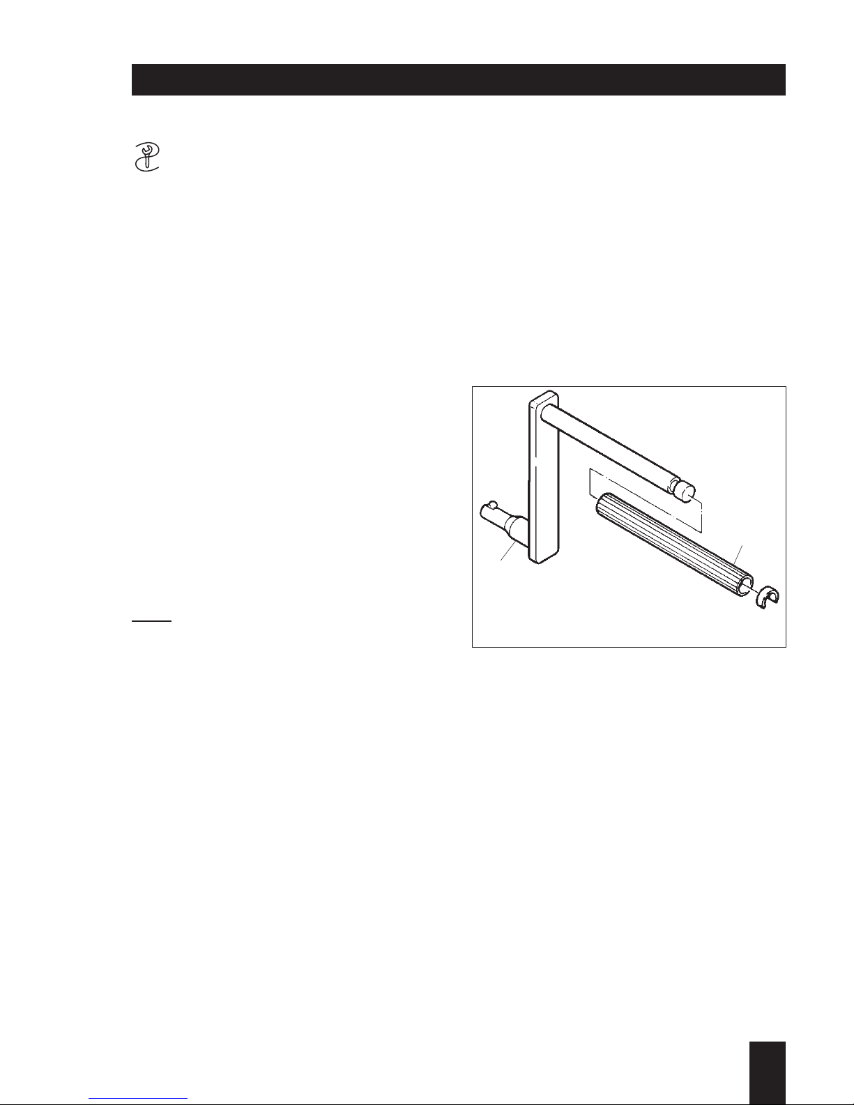
Version A 04.10.1
Standard crank handle:
This handle can be replaced at any time
by one with kick-back damping if this
becomes necessary or is required by
regulations.
Attention !
There is a risk of injury if the shaft of the
crank handle or its tubular handgrip are
worn.
Preparations: –
Demontage: –
Inspection / repair:
– Visual inspection.
– Inspect shaft 1 and tubular handgrip 2
for wear or breakage.
Note:
If the shaft of the crank handle is worn,
always renew the complete handle.
The tubular handgrip can be renewed
separately if necessary.
2
L / M . . 09.96
191
A 04.00 Start mechanical
A 04.10 Crank handle
2
1
–
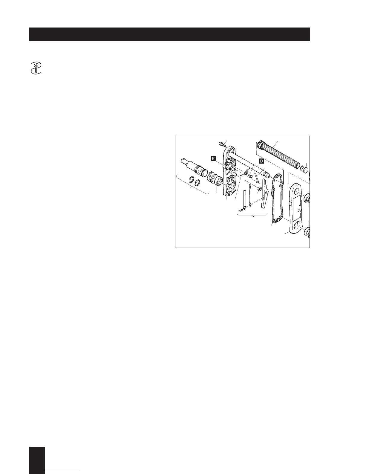
Version A 04.10.2
Handle with kick-back damping:
The version for M .. engines is marked A
on its housing, and takes the place of the
standard crank handle if required.
Attention !
There is a risk of injury if the shaft of the
crank handle or its tubular handgrip are
worn.
Preparations: –
Demontage:
– Remove parts in the order 1 ... 3 as
illustrated.
– Remove machine screws 4.
– Take off cover 5 with great care, so that
leaf spring 11 cannot escape.
Risk of injury!
– Remove parts in the order 6 ... 10 as
illustrated.
– Hold torsion spring 13 in position in
order to maintain its tension.
– Pull leaf spring 11 away from its locking
pin and out of the hook eye on torsion
spring 13.
– Relieve torsion spring tension with a
screwdriver blade.
Caution - risk of injury!
– Take off parts 12 and 13.
Housing 14 remains in position with the
other parts.
2
L / M . . 09.96
192
A 04.00 Start mechanical
A 04.10 Crank handle
47
8
15
14 13
12
11
10
9
6
5
1
6
1
5
3
A

Inspection / repair:
– Visual inspection:
– Renew the complete starting handle if
there is any damage in the area of
cover 5 and/or housing 14.
– If necessary, renew pivot bushings 15
and shaft sealing ring 16.
– Examine tubular handgrip 7 for wear
and/or other damage, particularly in the
splined area.
– Install end plug 8, avoiding damage to
the splines. The end plug must installed
to prevent dirt and water from entering.
– Check condition of bushing and leaf
spring at lever 9.
– Check condition of leaf spring 11 and
torsion spring 13.
Renew in case of doubt.
– Check shaft 3 for wear and/or other
forms of damage.
– Renew O-rings and small parts.
2
L / M . . 09.96
Assembling:
– Install parts 13 and 12.
Use thread sealant D.
– Make sure that the torsion spring is not
trapped; insert its longer end into the
groove on the corresponding locating
pin.
– Preload torsion spring 13 against the
normal spring pressure until the hook
eye of the spring engages behind the
eye of the through-hole.
Caution - risk of injury!
– Hold torsion spring 13 in position to pre-
vent spring pressure from being lost.
– Push leaf spring 11 into the hook eye
on torsion spring 13 and place on
locking pin.The rolled end of the leaf
spring must face toward the center of
the housing.
– Attach lever 9.
– Push on tubular handgrip 7/8.
Check splines, lever and leaf springs for
free movement.
– Apply app. 50 grams of lubricant K to
the inside of housing 14 and over all
mechanical parts.
– Place a new gasket 6 on the housing.
– Carefully place cover 6 over tubular
handle 7.
– Insert machine screws 4 and tighten
them evenly in a crosswise pattern.
– Install shaft 3 in the order 3 ...1 as
illustrated.
– Check operation of the complete crank
handle.
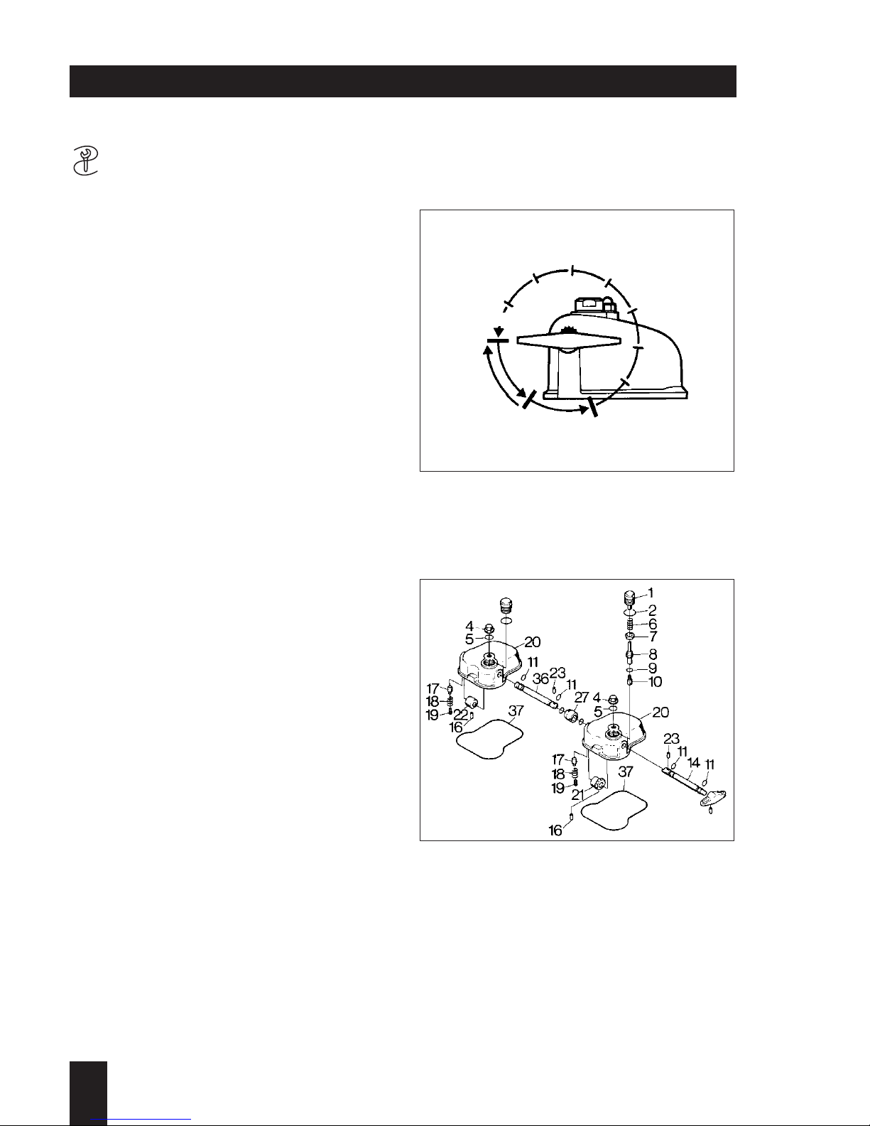
–
The automatic decompressor has the
following positions; Fig. 93:
0 = Operating position, with engine
running
1 = Permanent decompression, automatic
device switched off
2 = Automatic decompressor switched on,
engine compression is built up automatically after about 8 turns of the
handle.
Detaching:
– Unscrew cap nut (94/4) with sealing ring
(94/5).
– Take off cover (94/20) with gasket
(94/37).
On two-cylinder engines, shafts (94/14)
and (94/36) are connected together by
coupling sleeve (94/27) and 2 locking
collets (94/23). Camwheel (94/22) is then
used at the second cylinder (flywheel
side) instead of the gearwheel.
Dismantling the automatic decompressor:
– Unscrew and remove screw plug (94/1).
– Take out sealing ring (94/2), spring
(94/6), cap (94/7) and lifting pin with
shims and pressure pin (94/8, 9, 10).
– Unscrew threaded rod (94/19) and
remove spring (94/18) and pressure pin
(94/17).
– Using a suitable split-pin driver, drive
locking collet (94/16) about 3 mm into
gearwheel (94/21).
– Turn the gearwheel through 180° and
pull the locking collet out with pliers.
– Take out shaft (94/14) and gearwheel.
2
L / M . . 09.96
93
94
A 04.00 Start mechanical
A 04.20 Automatic decompressor (M 31, M 40, M 41)
L3 / 1
12
0
kompr.
dekompr. dekompr.autom.
L3 / 42
 Loading...