

Hatz Diesel 1D42, 1D50, 1D81, 1D90 Instuction Manual
0000 433 216 11-USA-EPA IV-CARB
01.12-0.1
Printed in Germany
1D 42.
1D 50.
1D 81.
1D 90.
33
INCLUDES SUPPLEMENTAL INFORMATION TO THE
OWNER’S MANUAL FOR MODEL YEAR 2012 EPA
CERTIFIED NONROAD COMPRESSION-IGNITION ENGINES
INCLUDES SUPPLEMENTAL INFORMATION TO THE
OWNER’S MANUAL FOR MODEL YEAR 2012 CALIFORNIA
REGULATIONS FOR HEAVY-DUTY OFF-ROAD ENGINES
Translation of the
ORIGINAL INSTRUCTION BOOK
1
A new HATZ diesel engine is ready to work for you
This engine is intended only for the purpose determined and tested by the manufacturer of the
equipment in which it is installed. Using it in any other manner contravenes the intended purpose.
For danger and damage due to this, Motorenfabrik HATZ assumes no liability. The risk is with the
user only. Use of this engine in the intended manner presupposes compliance with the maintenance
and repair instructions laid down for it. Noncompliance leads to engine breakdown.
Please study this Instruction Book before you start the engine for the first time: it will help you to
avoid accidents, to operate the engine correctly, to perform maintenance work and to keep the engine
operating at full efficiency for a very long time.
Please follow all maintenance references carefully including the schedule for Model Year 2012
EPA certified nonroad compression-ignition engines and for Model Year 2012 CARB certified
Heavy-Duty off-road engines to prevent our environment.
Please pass this Instruction Manual on to the next user or to the following engine owner.
Always have service work performed by qualified specialists. To this effect, we recommend that you
consult one of the 500 HATZ service stations. There, your engine is repaired by staff who constantly
undergo training and who use both original HATZ spare parts and HATZ tools. The world-wide HATZ
service network is also available to you for consultation and spare parts supply.
For the address of your nearest HATZ service station, please refer to the attached list or the internet
under: www.hatz-diesel.com
The installation of inappropriate spare parts may cause problems. We cannnot accept any liability for
damage or consequential damage resulting therefrom.
Thus, we recommend that you use original HATZ spare parts. These parts are manufactured following the strict HATZ specifications and ensure, thanks to their perfect fit and function, maximum operating reliability. For the reference number, please consult the attached spare part list or the internet
under: www.hatz-diesel.com. Please take the complete spare parts kits in Table M00 into account.
In the interests of technical progress we reserve the right to introduce modifications.
MOTORENFABRIK HATZ GMBH & CO KG

Page
1. Important notes on safe operation
of the engine 3
2. Description of engine 5
3. General information 7
3.1. Technical data 7
3.2. Transport 8
3.3 Instructions for installation 8
3.4. Load on engine 8
3.5. EPA/CARB-type plates 9
3.6. Emission-related installation
instructions 9
4. Operation 10
4.1. Before initial start-up 10
4.1.1. Engine oil 10
4.1.2. Oil bath air cleaner 10
4.1.3. Fuel 11
4.1.4. Mechanical oil pressure monitor 12
4.2. Starting the engine 13
4.2.1. Preparations for starting 14
4.2.2. Starting with the handle 15
4.2.3. Starting in cold weather 16
4.2.4. Electric starter 17
4.3. Stopping the engine 18
5. Maintenance 20
5.1. Maintenace summary 20
5.2. Maintenance every 8 – 15 hours
of operation 22
5.2.1. Check engine oil level 22
5.2.2. Check air intake point 22
5.2.3. Air cleaner blockage indicator 22
5.2.4. Checking cooling air zone 23
5.2.5. Checking the water trap 23
Page
5.3. Maintenance every 250 hours
of operation 24
5.3.1. Oilbath air cleaner maintenance 24
5.3.2. Changing engine oil, renewing
oil filter 25
5.3.3. Checking and adjusting
valve clearances 26
5.3.4. Clean the cooling air system 27
5.3.5. Checking threaded connections 28
5.3.6. Cleaning mesh insert in exhaust
silencer 28
5.4. Maintenance every 500 hours
of operation 29
5.4.1. Renewing fuel filter 29
5.4.2. Dry-type air cleaner maintenance 30
6. Malfunctions – Causes – Remedies 32
7. Work on the electrical system 36
8. Protective treatment 36
Declaration for Incorporation 37
SUPPLEMENTAL INFORMATION TO
THE OWNER’S MANUAL FOR Model
Year 2012 EPA CERTIFIED NONROAD
COMPRESSION IGNITION ENGINES 39
SUPPLEMENTAL INFORMATION
TO THE OWNER’S MANUAL FOR
Model Year 2012 CALIFORNIA
REGULATIONS FOR HEAVY-DUTY
OFF-ROAD ENGINES 55
2
This symbol draws attention to important safety precautions.
Please comply with them most carefully in order to avoid any risk of injury to persons or
damage to materials.
General legal requirements or safety regulations issued by the competent authorities or
industrial accident insurers are also applicable.
Contents

3
1. Important notes on safe operation of the engine
HATZ diesel engines are economical, strongly built and long-lasting. They are therefore frequently
chosen for commercially and industrially operated equipment and machinery.
Since the engine forms part of the finished equipment or machine, its manufacturer will take all the
applicable safety regulations into account.
Nevertheless, we give below certain additional comments on operating safety, and would recommend
you to note them carefully.
Depending on the manner in which the engine is installed and its intended application, the equipment
manufacturer or operator may have to attach additional safety devices and prohibit potentially hazardous aspects of operation, for example:
– Parts of the exhaust system as well as the surface of the engine are of course hot during operation
of the engine, but also when it is still cooling down after use, and must not be touched.
– Faulty wiring or incorrect operation of electrical equipment may lead to sparks forming, and must
be avoided as a potential fire hazard.
– Rotating parts must be shielded against accidental contact when the engine is installed in other
equipment or machinery.
Guards are available from HATZ to protect belt drives, cooling fans and generators.
– Before attempting to start the engine it is essential to have studied the starting information in the
Instruction Book; this is particularly important on engines started with a starting handle.
– Mechanical starting devices must not be used by children or persons of insufficient physical
strength.
– In order to benefit from the advantages of the starting handle with kick-back damping, it must be
used precisely as recommended in this Instruction Book.
– Before starting the engine, ensure that all the specified protective guards are in place.
– The engine must only be operated, serviced or repaired by persons who have received the appro-
priate training.
– Keep the starting handle and the key out of reach of unauthorized persons.
– Never run the engine in closed or badly ventilated rooms.
Do not breath in emissions - danger of poisoning!
– Also fuel and lubricants could contain poisonous components. Please follow the instructions of the
mineral oil producer (safety data sheets).

4
Important notes on safe operation of the engine
– Stop the engine before performing any maintenance, cleaning- and repair work.
– Stop the engine before refuelling.
Never add fuel near a naked flame or a source of sparks.
Don’t smoke. Don’t spill fuel.
– Keep explosive materials as well as flammable materials away from the engine because the exhaust
gets very hot during operation.
– Wear close-fitting clothing when working on a running engine.
Please don’t wear necklaces, bracelets or any other things which you could get caught with.
– Please pay attention to all advice- and warning stickers placed on the engine and keep them in legi-
ble condition. In case a label has come off or is no longer clearly legible, it must be replaced immediately. To this effect, please contact the HATZ service station in your area.
– Note that any unauthorized modification to the engine absolves its manufacturer from liability for
the consequences.
Regular servicing in accordance with the details provided in this Instruction Book is essential to keep
the operating reliably and to ensure the exhaust quality of the engine.
In case of doubt, always consult your nearest HATZ service station before starting the engine.
5
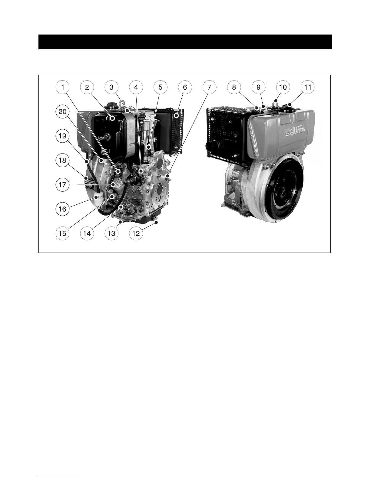
2. Description of engine
1D42 • 1D50 • 1D81 • 1D90 S / Z engines
1
2391 / 12 2391 / 7
1 Cooling air inlet
2 Dry-type air cleaner
3 Decompression lever
4 Stop lever
5 Cooling air outlet
6 Silencer (muffler)
7 Guide sleeve for starting handle
8 Cylinder head cover
9 Cold-start oil metering device
10 Suspension lug
11 Tank filler cap
12 Oil drain plug, governor housing
13 Oil drain plug, governor side
14 Speed control lever
15 Oil filler pipe and dipstick
16 Fuel filter
17 Oil filter
18 Type plate
19 Tank drain plug
20 Combustion air intake
6
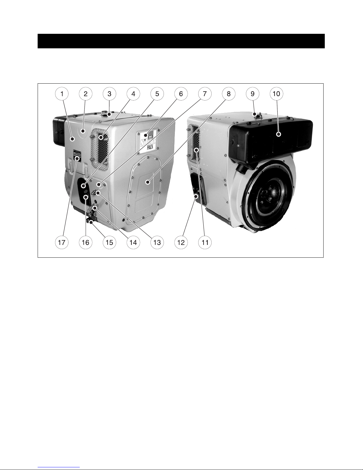
Description of engine
Fully-encapsulated version
1D42C • 1D81C engines
2
1 Capsule
2 Decompression lever
3 Cold-start oil metering device
4 Combustion and cooling air intake
5 Oil filter
6 Cleaning hatch
7 Side panels
8 Hold for starting handle
9 Suspension lug
10 Silencer (muffler), encapsul.
11 Cooling air outlet
12 Battery connection and central plug
for electrical system
13 Stop lever
14 Speed control lever
15 Oil drain plug
16 Oil filler and dipstick
17 Type plate
2392 / 1 2392 / 4

7
3. General information
3.1. Technical data
1)
These data are approx.-values. The max. mark on oil dipstick counts.
2)
Exceeding these limits causes engine breakdown.
Type 1D42. 1D50. 1D81. 1D90.
Engine models S, Z, C S, Z S, Z, C S, Z
Mode of operation air-cooled four-stroke diesel engine
Combustion method Direct-fuel injection
Number of cylinders 1 1 1 1
Bore / stroke mm 90 / 70 97 / 70 100 / 85 104 / 85
Displacement
cm
3
445 517 667 722
Engine oil content without filter
with filter
approx. L
1.1
1)
1.2
1)
1.4
1)
1.5
1)
1.8
1)
1.9
1)
1.8
1)
1.9
1)
Volume of oil between
„max“ and „min“ marks
approx. L
0.4
1)
0.5
1)
0.9
1)
0.9
1)
Consumption of lubrication oil
after running-in period
approx. 1 % of fuel consumption at full load
Engine oil pressure
Oil termperature 100 ± 20 °C
min. 0.6 bar at 850 r.p.m.
Direction of rotation
looking at the flywheel
counterclockwise
Valve clearance at 10 - 30 °C
Inlet
Exhaust
mm
0.10
0.20
0.10
0.20
0.10
0.20
0.30
0.30
Max. angle from vertical in any
direction (continuous operation)
max. 30°
2)
30°
2)
25°
2)
25°
2)
Weight (incl. fuel tank, air-cleaner,
exhaust silencer and electric starter)
Engine model S
Engine model Z
Engine model C
approx. kg
approx. kg
approx. kg
78
81
100
83
85
–
105
107
126
106
108
127
Battery capacity min / max 12 V - 45 / 88 Ah • 24 V - 36 / 55 Ah
Model S: non-encapsulated, normal system of balancing
Z: non-encapsulated, add. system of balancing
C: SILENT PACK, add. system of balancing
3.2. Transport
A lug is provided on top of the engine
as standard equipment, so that the engine can be lifted safely. It is not suitable for
lifting complete machines or similar with the
engine attached, and this is strictly prohibited.
(See Chapter 2.)
3.3. Instructions for installation
If you have an engine which is not yet installed
in a machine and still has to be installed, make
sure that the Assembly Instructions for HATZ
Diesel Engines are complied with prior to installation. These Assembly Instructions contain important information about safe assembly of the
engine and are available from your the HATZ
service center in your area.
Pending complete installation, the engine
must not be started !
Moreover, we would like to point out that in this
case, commissioning of the machine is also prohibited until it has been verified that the machine
into which this engine is to be incorporated
complies with all the safety precautions and regulations provided by law.
Refer also to the Declaration for Incorporation
at the end of these Operating Instructions.
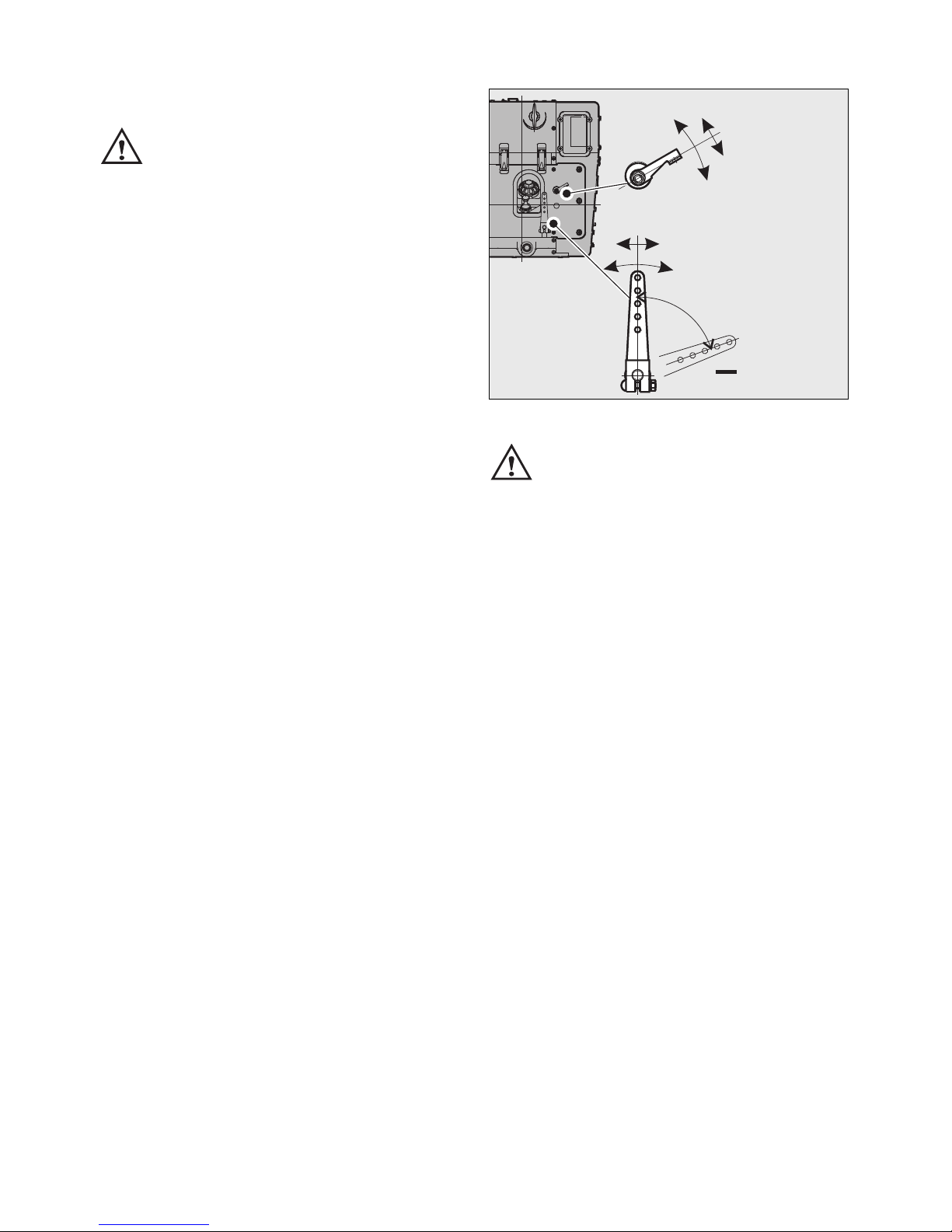
3
The permitted loads and elements on
the speed adjusting lever and the stop
lever should be observed as an exess can lead
to damage to the contacts and inner governor
parts.
3.4. Load on engine
See supplemental information for EPA certified
engines, Page 39; resp. supplemental information for California regulations for off road
engines, Page 55.
70°
F 120 N
M 12.6 Nm
–
–
F 10 N
M 0.35 Nm
–
–
<
<
<
<
START
STOP
+
8
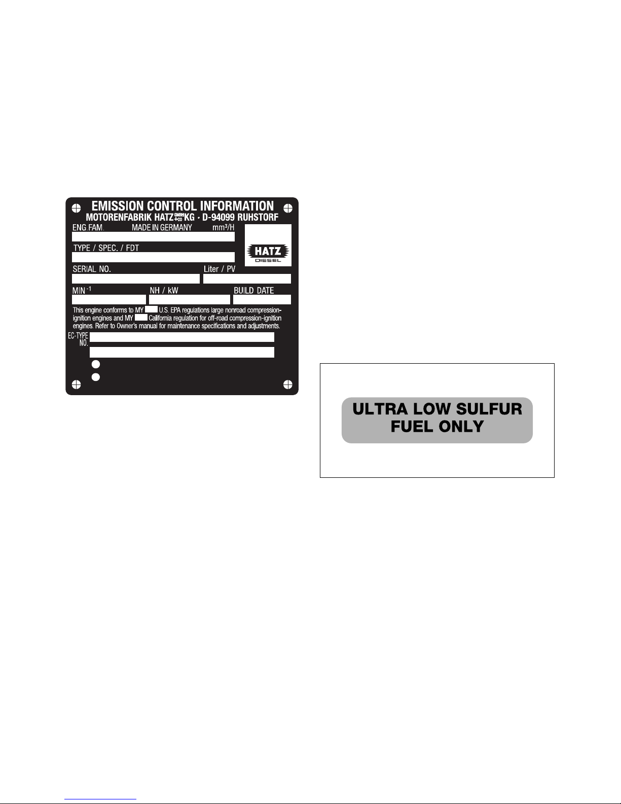
3.5. EPA/CARB-type plates and
fuel label
The layout of the EPA/CARB-type plate depends
on the engine application and is placed on the
crankcase resp. on the capsule (chapt. 2).
It includes the following emission control information (Figure 4a):
Type plate
4a
➀ EPA/CARB-Engine Family Number
➁ engine type / spec. (only for special
equipment) /Fuel Delivery Timing
➂ engine number
➃ max. engine rated speed
➄ build date
➅ displacement
➆ rated power
➇ emission control system information (see
page 42 and 58)
➈ “variable speed” or “constant speed only”
(if requested)
The type plate also states the applicable emission-related power category of the engine.
The figure of the lable shows a EPA/CARB (50
states) label. The text referring to the emission
regulation gets printed depending on the engine
equipment (EPA or EPA and CARB).
Every engine is equipped with an additional
loose engine type plate. If the original type
plate on the engine is not readily visible after
the engine is installed in the equipment then
the second loose type plate must be attached
on the equipment in such a manner that it is
readily visible to an average person.
For any offer as well as spare parts orders it is
necessary to mention the following data (also
see spare parts list, page 1):
➁ engine type / spec.
(only for special equipment)
➂ engine number
➃ max. engine rated speed
Always install the engine for its intended application in order to comply with EPA and CARB
emission regulation requirements.
Fuel label
4b
The engine must be operated with “ULTRA LOW
SULFUR FUEL ONLY”.
The fuel label is placed nearby the fuel inlet.
If there was no fuel tank mounted to the engine,
the label has to be permanently attached to the
equipment near the fuel inlet.
3.6. EMISSION-RELATED
INSTALLATION INSTRUCTIONS
See supplemental information for EPA certified
engines, Page 39; resp. supplemental information for California regulations for off road
engines, Page 55.
0000 053 657 02
VARIABLE SPEED. ULTRA LOW SULFUR FUEL ONLY.
Power Category:
EMISSION CONTROL SYSTEM INFORM.:
➀
➁
➂
➃
➄
➅
➆
➈
➇
9
4. Operation
4.1. Before initial start-up
Engines are normally delivered without fuel and
oil.
4.1.1. Engine oil
Qualified are all trademark oils which fulfil at
least one of the following specifications:
ACEA – B2 / E2 or more significant
API – CD / CE / CF / CF-4 / CG-4 or more
significant.
If engine oil of a poorer quality is used, reduce
oil change intervals to 150 hours of operation.
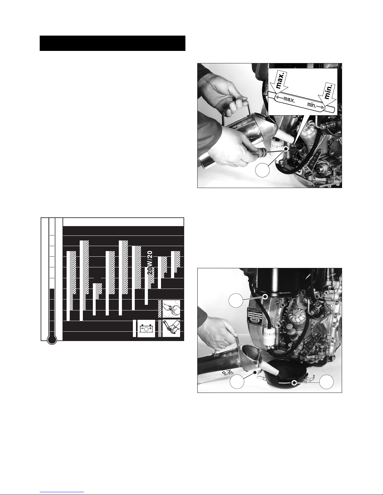
Oil viscosity
5
Please select the recommended viscosity depending on the ambient temperature at which
the engine is operated.
Inappropriate engine oil may shorten the
engine’s service life significantly.
The engine must be in a horizontal position before adding oil or checking the oil level.
6
– Pull out dipstick „1“ and add engine oil of the
correct specification and viscosity up to the
„max“ mark on the dipstick; (Chapter 3.1.).
4.1.2. Oil bath air cleaner
7
– Take off the oil reservoir and fill it up to the
mark „1“ using engine oil.
– Attach the oil reservoir, making sure that seal-
ing ring „2“ is correctly seated and catches „3“
are tight.
2393 / 6
2
3
1
1
-40
-30
-20
-10
0
10
20
30
40
50
10 4
86
68
50
32
14
-4
-22
-40
OIL: SAE...
°C°F
5W/30
5W/40
10W/40
10W/30
15W/40
30
40
122
10 W
10
4.1.3. Fuel
Only refuel when engine is stopped.
Never refuel close to open flames or
flammable sparks, don’t smoke. Use only pure
fuel and clean replenishing cups. Don’t spill
the fuel.
All diesel fuels sold as fuel and complying with
the following minimum specification can be
used:
EN 590 or
BS 2869 A1 / A2 or
ASTM D 975 - 1D / 2D
Important !
The use of fuels of different specifications requires the prior written consent of the HATZ
headquarters.
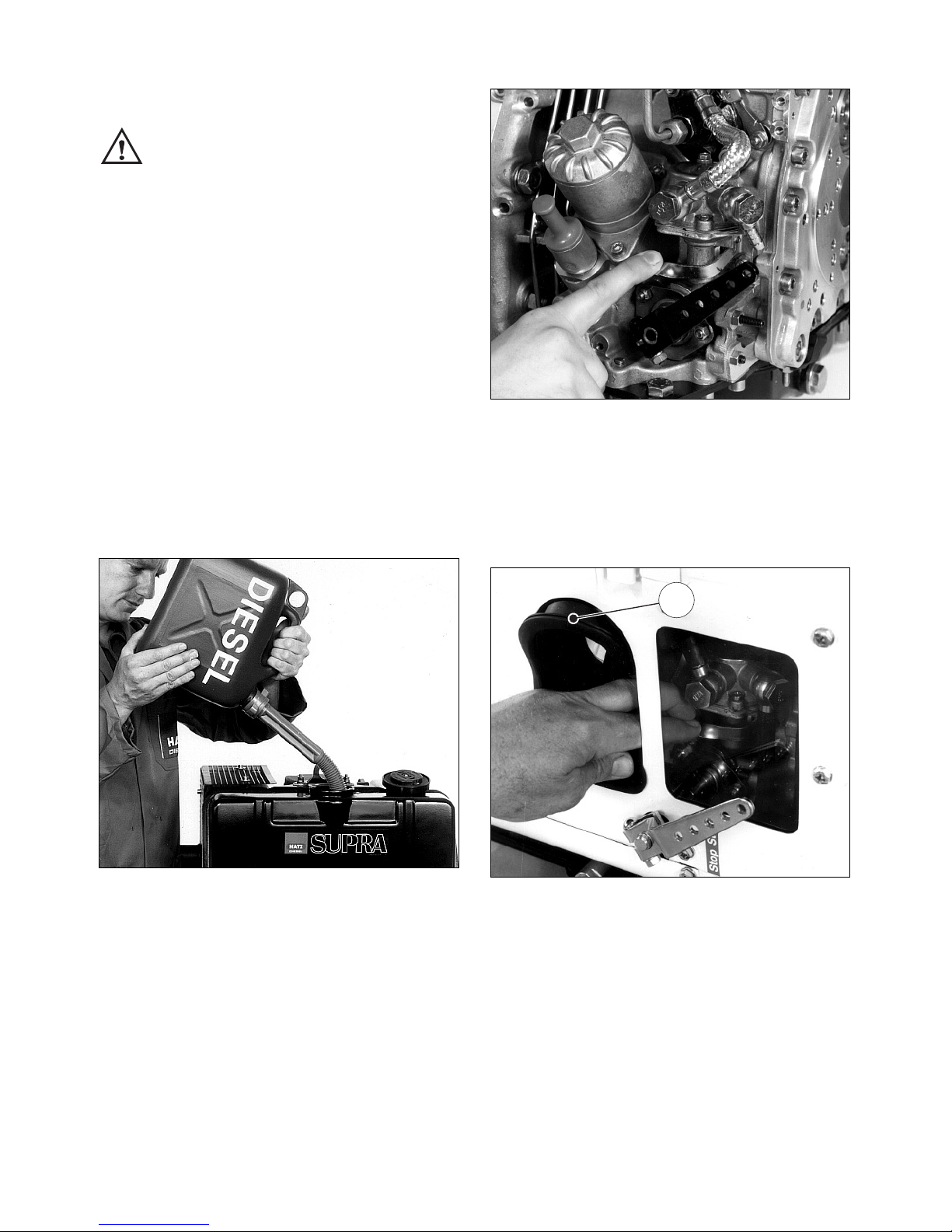
8
– Before the first start or if the fuel tank has
been run dry, completely fill the fuel tank with
diesel.
The fuel system is bled automatically if the fuel
tank is attached to the engine or located higher
than the injection pump.
9
– If the fuel tank is not mounted on top of the
engine, or is at a lower level, operate the lever
on the fuel feed pump until fuel is heard to
flow back to the tank through the return line.
10
– On fully encapsulated engines, move sleeve
„1“ to one side to gain access to the feed
pump.
After operating the feed pump, make sure that
the sleeve is replaced correctly and makes a
good seal.
1
2292 / 4
2287 / 11
2286 / 2
11
At temperatures below 0 °C, winter-grade fuel
should be used or parafin added to the fuel well
in advance.
4.1.4. Mechanical oil pressure
monitor
(optional extra)
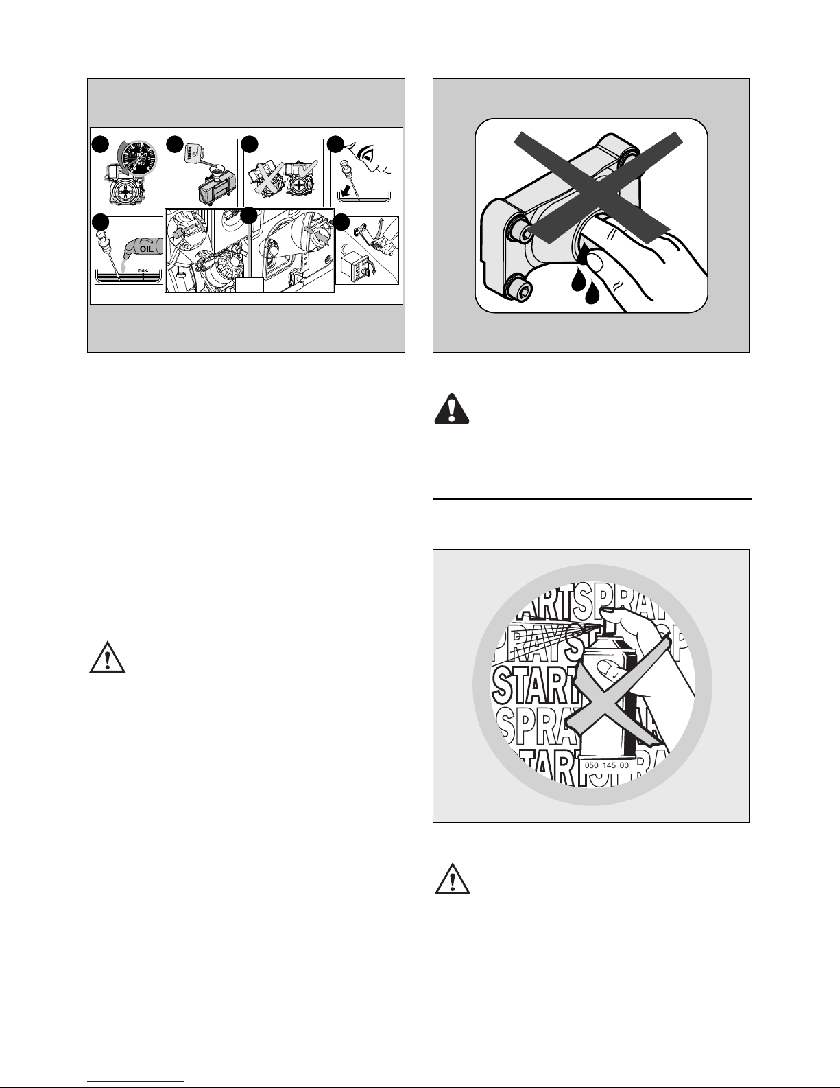
The mechanical oil pressure monitor should be
activated:
• when first filling, or after running the fuel tank
dry.
• if engine shut down automatically because lu-
bricating oil supply was inadequate.
• after freeing it by turning at low temperatures
(Chapter 4.2.4.)
• after replacing the fuel filter, Chapter 5.4.1.
– Add fuel, chap. 4.1.3.
– Check engine oil level, chap. 5.2.1.
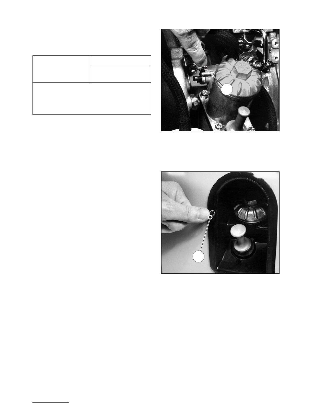
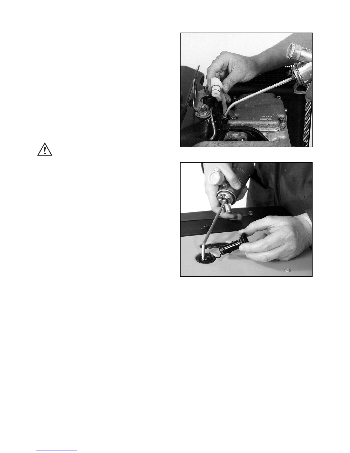
11
– To activate the monitor, press lever „1“ for
approx. 15 seconds.
12
– If the engine has a full capsule, press pin „1“
for app. 15 seconds.
– If the engine has a fuel feed pump, operate its
lever for several strokes at the same time
(Figs. 9 and 10).
– Re-assemble all parts repositioned or re-
moved. Check that capsule elements make a
good seal.
2392 / 12
1
1
Lowest ambient
temperature when
starting, in °C
Paraffin content for:
Summer Winter
fuel fuel
0 up to –10 20 % –
–10 up to –15 30 % –
–15 up to –20 50 % 20 %
–20 up to –30 – 50 %
12
13
Instructions to activate the mechanical oil pressure control are mentioned on the sticker placed
on the engine.
IMPORTANT !
Even with mechanical oil pressure monitoring
the oil level must be checked every 8 – 15
operating hours (Chapter 5.2.1.).
4.2. Starting the engine
Do not run the engine in closed or
badly ventilated rooms – danger of
poisoning ! Before the engine is started, always make sure that nobody is in the danger
area (moving parts on engine or machinery)
and that all safety guards are in place.
Check that the starting handle is in good condition: renew tubular grip if broken, worn drive pin
etc.
Lightly grease the sliding-contact area between
the starting handle and the guide sleeve.
14
Risk of serious injury from rotating parts.
Never put your hands in the guide sleeve of the
cranking device while the engine is running.
15
Never use any spray starting aids.
050 145 00
L3 / 250
WARNING
0000 053 755 00
0000 051 268 02
1 3 4
5
6
2
7
15s
13
4.2.1. Preparations for starting
– If possible, disengage the engine from any
driven equipment. The auxiliary equipment
should always be placed in neutral.
16
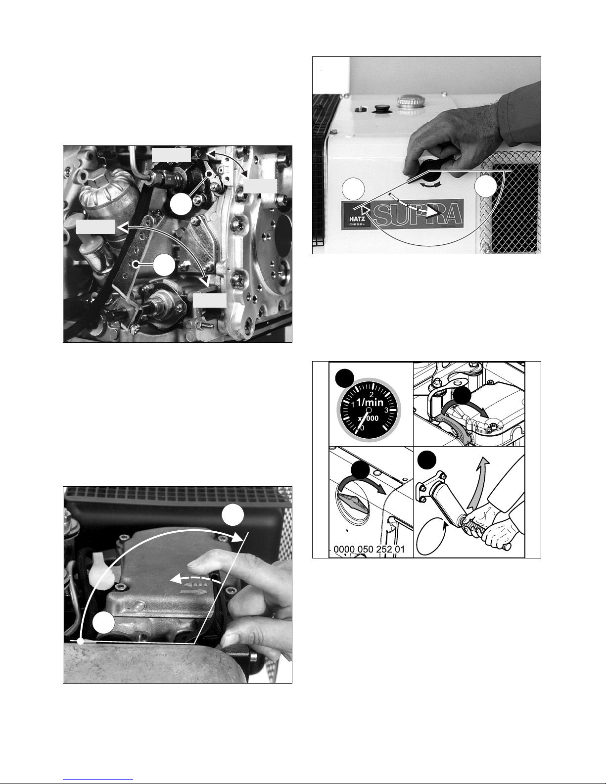
– Set speed control lever „1“ to a position be-
tween 1/2 START and max. START, according
to requirements. Selecting a lower engine
speed will reduce smoke when starting.
– Make sure that stop lever „2“ - if fitted - is in
the operating „START“ position.
17
18
– Turn the decompression lever until stop „1“ is
reached. In this position the automatic decompression system is heard to engage and the
engine can then be started; Figs. 17 and 18.
19
After the automatic decompression device has
engaged at its limit stop, five turns of the crank
handle are needed for the engine to build up
compression and fire again.
2
2
3
5x
1
1
0
2292 / 6
1
0
2283 / 4
2396 / 3
2
1
START
START
STOP
STOP
14
4.2.2. Starting with the handle
For preparations to start the engine,
see Chapter 4.2.1.
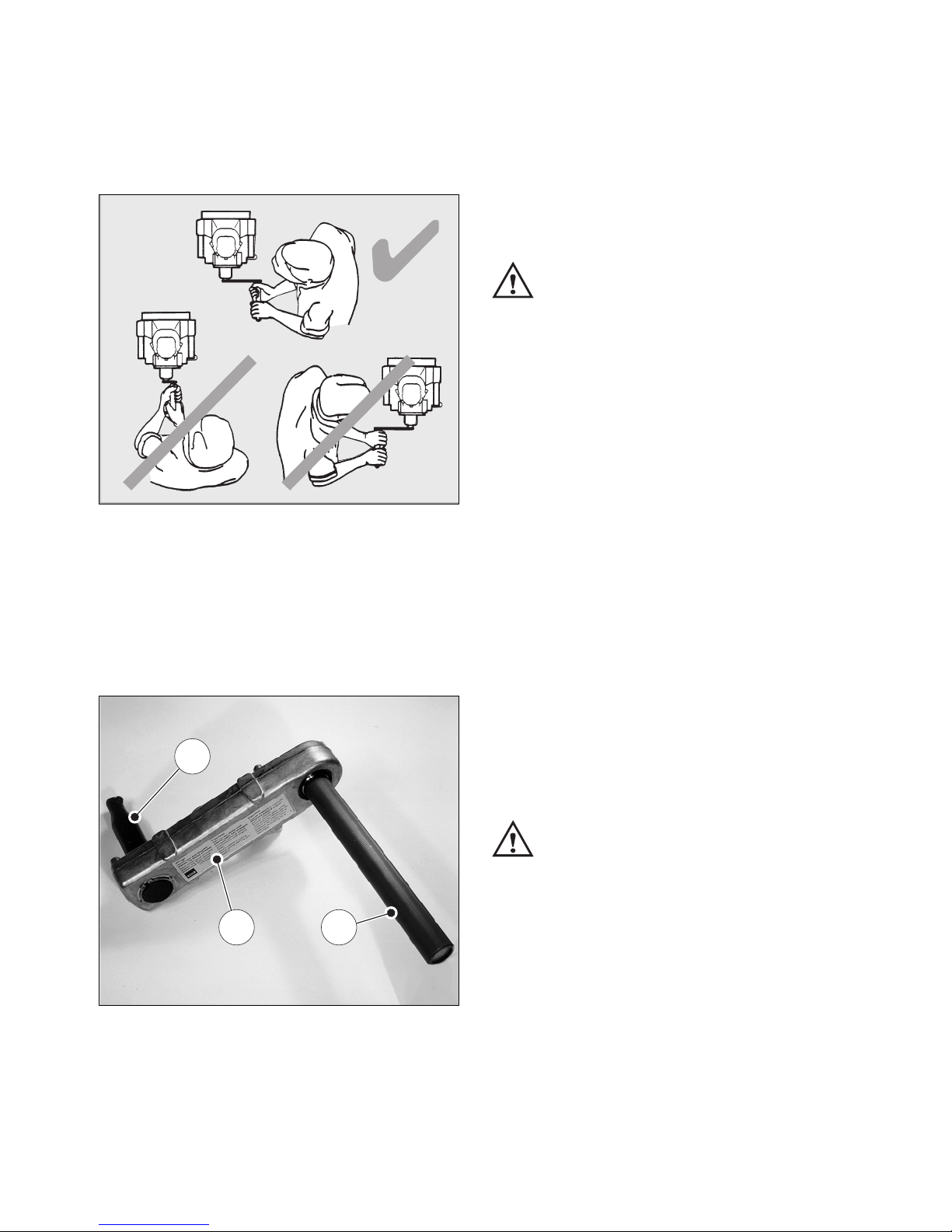
20
For correct position to adopt when starting the
engine, see Fig. 20.
Starting with the handle with kick-back
damping (retrofit)
21
– Always hold tubular grip „1“ with both hands.
– Turn the handle slowly until the pawl engages
in the ratchet, then increase turning force to
build up speed. The highest speed must have
been reached when the decompression lever
returns to the „0“ position (compression). As
soon as the engine has started, pull the starting handle out of the guide sleeve.
You must hold the tubular grip firmly to
maintain contact all the time between
the starting handle and the engine. Maintain
turning force during the entire hand starting
operation.
If backfiring occurs when starting the engine because the crank handle was not turned firmly
enough, the brief reverse rotation at the handle
tube separates the link between crank lug „2“
and driving dog „3“ (Fig. 21).
– If the engine begins to run backwards after
backfiring (smoke emerges from air cleaner),
release the crank handle immediately and stop
the engine (Chapter 4.3.).
– To restart the engine, wait until it has come to
a standstill, then repeat the starting preparations.
Starting by means of the standard
starting crank
In the countries of the European Union,
starting cranks without kick-back dam-
ping must not be used.
For preparations to start the engine,
see Chapter 4.2.1.
– For correct position to adopt when starting the
engine, see Fig. 20.
3
2 1
2395 / 4
15
– Take hold of the starting handle with both
hands and turn it at increasing speed. The
maximum speed of rotation must have been
reached by the time the decompression lever
has returned to the „0“ position (compression). As soon as the engine has started, pull
the starting handle out of the guide sleeve.
– If the engine backfires because the crank han-
dle was not turned firmly enough (the engine
may even start to run backwards), release the
crank handle immediately and stop the engine
(Chapter 4.3.).
There is a risk of injury from the
rotating crank handle.
– To restart the engine, wait until it has come to
a standstill, then repeat the starting preparations.
Safety precaution
For greater protection against accidental injury
when starting with the handle, a handle with
kick-back damping can be used.
4.2.3. Starting in cold weather
At temperatures below app. –5 °C, always turn
the engine over to ensure that it rotates freely.
– Move the speed control lever to the START
position; Fig. 16.
– Place decompression lever in central position
between „0“ and „1“ (Fig. 17 and 18).
– Turn the engine over with the starting handle
until it is felt to rotate more freely (10 – 20
turns of the starting handle).
– If mechanical oil pressure monitoring is
fitted, press lever „1“ or pin „1“ in for about
15 seconds (Figs. 11 and 12).
22
23
– Remove dirt from the cover of the metering
device and the surrounding area. Pull off the
cover; Figs. 22 and 23.
– Add a free-flowing lubricating oil to the
housing until the level reaches the upper rim.
Replace the cover and press it in firmly. Two
filling operations in succession are needed.
– Turn the decompression lever until
limit stop „1“ (fig. 17 and 18).
– After this, start the engine immediately.
Chap. 4.2.1. / 4.2.2.
2392 / 9
2283 / 8
16
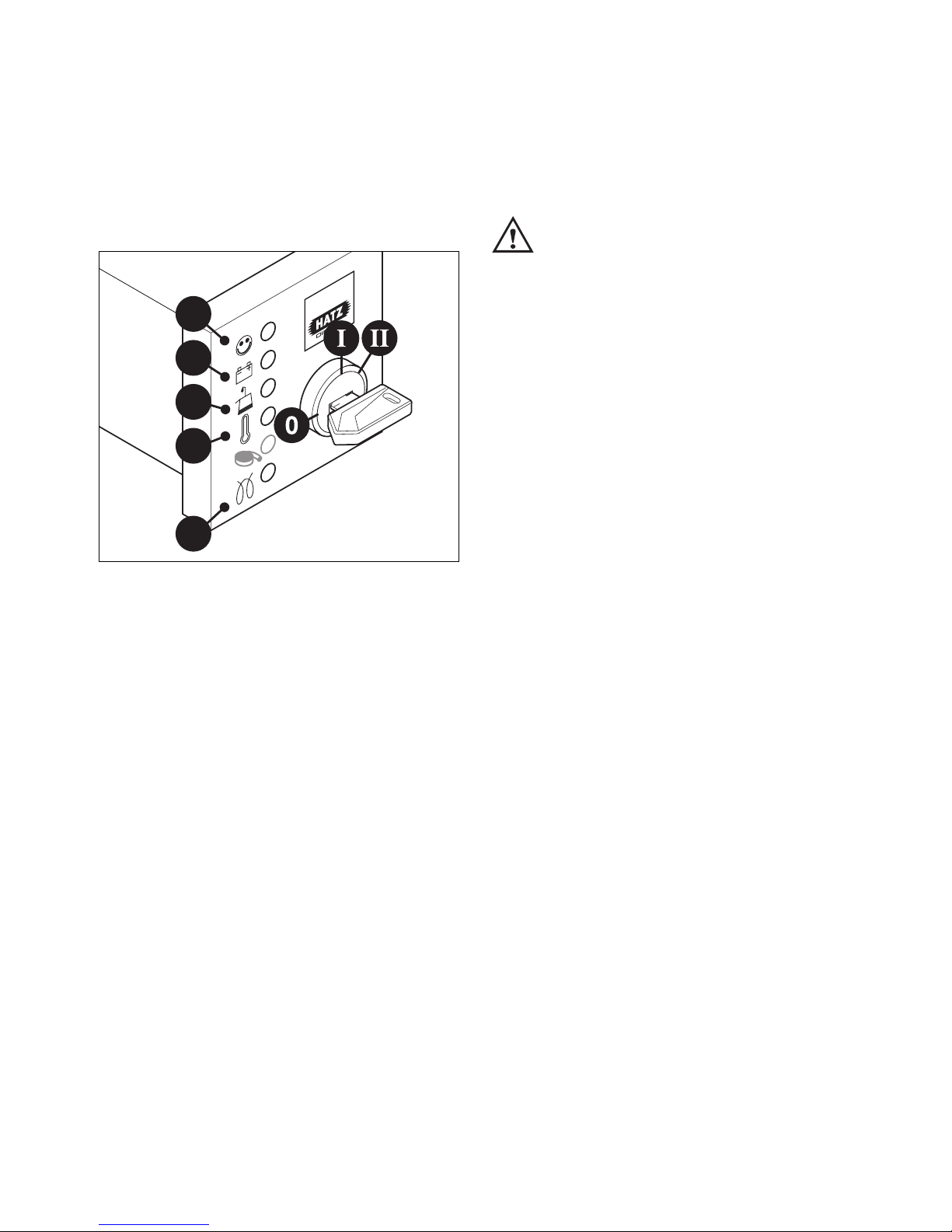
4.2.4. Electric starter
For preparations to start, see Chapter 4.2.1.
– The decompression lever remains in pos. „0“.
Starting procedure
24
– Insert the key to its stop and turn it to
position I.
– Battery charge telltale „2“ and oil pressure
warning „3“ must light up.
– Turn start key to position II (fig. 24).
– As soon as the engine runs, release the start
key. It must return to position I by itself and
remain in this position during operation.
The battery charge telltale and oil pressure
warning must go out immediately after starting. Indicator light „1“ is on when the engine is
in operation.
– If anything seems to be incorrect, stop the en-
gine immediately and trace and rectify the fault
(chapt. 6).
– The engine temperature display „4“ (additional
equipment) lights up if the temperature at the
cylinder head becomes too high.
Switch off the engine and trace and eliminate the cause of the problem, chap. 6.
– Always turn the start key back to position 0
before re-starting the engine. The repeat lock
in the ignition lock prevents the starter motor
from engaging and possibly being damaged
while the engine is still running.
Never operate the electric starter when
the engine is running or coasting to a
standstill. There is a risk of broken starter pinion or ring gear teeth.
Important:
If a start protection module is installed, the start
key has to be returned to position 0 for at least
8 seconds if the engine has failed to start before
a further attempt to start the engine can be
made.
Preheating device with automatic
heating timer
(additional equipment)
The preheating light „5“ lights up additionally at
temperatures below 0° Celsius (Fig. 24).
– After the light has gone out, start the engine
without delay.
1
2
3
4
5
17
Automatic electrical shutdown system
(additional equipment)
This is characterized by a brief flashing of all
pilot lamps once the starter key has been turned
to position I (Fig. 24).
Important !
If the engine cuts out immediately after starting
or switches off by itself during operation, a
monitoring element in the automatic shutdown
system has tripped. The corresponding indicator
light (Fig. 24, positions 2 - 4) will come on.
After the engine has stopped, the display continues to glow for about 2 minutes.
The electrical device then switches itself off automatically.
The display lights up again after the start key
has been turned back to position 0 and then to
position I again.
Trace and eliminate the cause of the operating
fault before trying to restart the engine
(see chapter 6).
The display light goes out when the engine is
next started.
Even with automatic shutdown monitoring the
oil level must be checked every 8 – 15 operating hours (Chapter 5.2.1.).
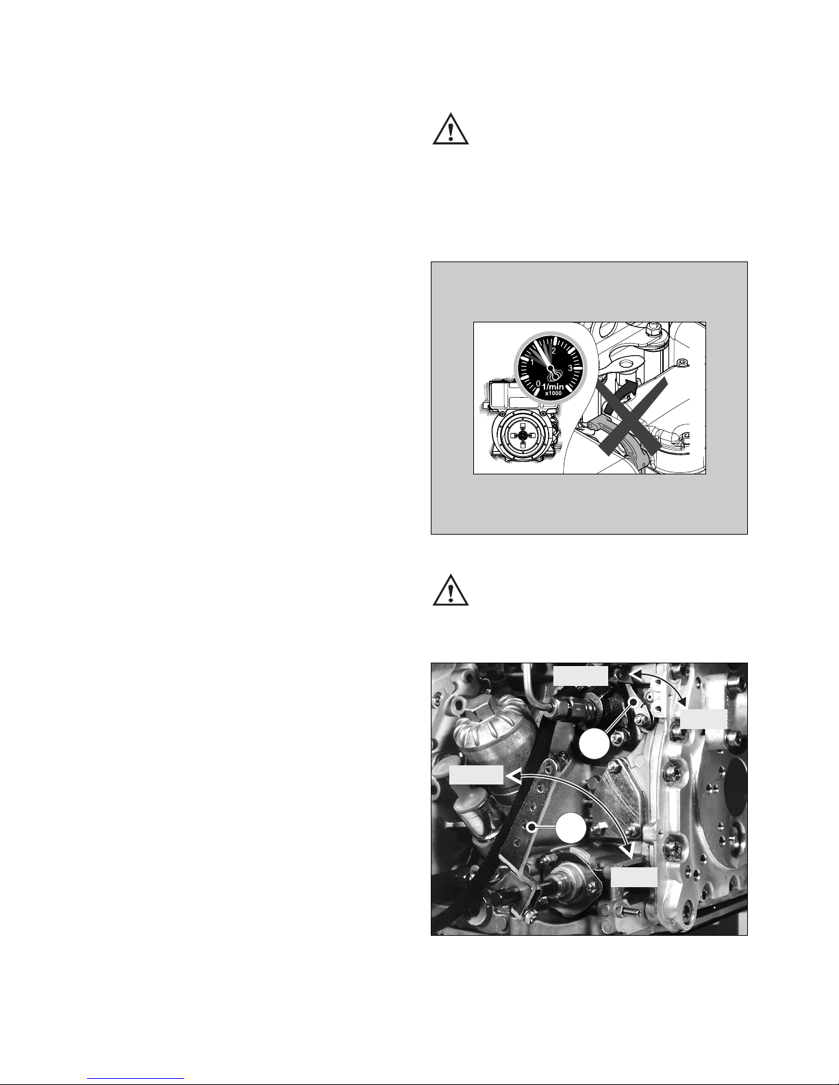
4.3. Stopping the engine
Never stop the engine by moving the
decompression lever. During breaks
in work or at the conclusion of the working period, keep the starting handle and starting key
in a safe place, out of reach of unauthorized
persons.
25
Never stop the engine by actuating the
decompression lever !
Risk of damage to the engine.
26
– Move speed control lever „1“ back to the
STOP position.
2396 / 3
2
1
START
START
STOP
STOP
0000 050 616 01
18
– On engines with the lower engine speeds
not accessible, move speed control lever „1“
back, then move stop lever „2“ in the STOP
direction. Hold it there until the engine has
stopped.
– Once the engine is not running any longer,
release the stop lever.
The stop lever is returned automatically to its
operating position START via a spring.
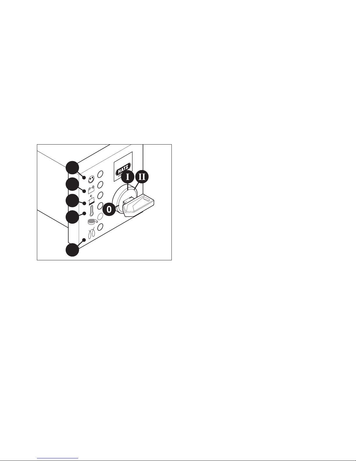
Electrical system
27
The charge „2“ and oil pressure telltales „3“
come on.
– Turn the key to the 0 position and pull it out.
The telltale lights must then go out.
Note:
Engines with an automatic electrical shutdown
system (Chapter. 4.2.4.) can also be switched
off by turning the start key back to position 0.
1
2
3
4
5
19

20
5. Maintenance
The engine must be stopped before any maintenance work is attempted.
Comply with legal requirements when handling and disposing of old oil, filters and
cleaning materials.
Keep the engine’s starting key and starting handle out of reach of unauthorized persons.
To immobilize engines with an electric starter, disconnect the negative battery terminal.
At the end of the maintenance work, check that all tools have been removed from the engine and
all safety guards, covers etc. replaced in their correct positions.
Before starting the engine, make sure that nobody is in the danger area (engine or driven
machinery).
5.1. Maintenance summary
Maintenace intervals Maintenance work required Chap.
Every 8 – 15 operating
hours or before daily
starting.
Check oil level.
Check area round combustion air input.
Check the air cleaner maintenance indicator.
Check the cooling air zone.
Check the water trap.
Check the lower part of the oilbath air cleaner for
correct oil level and freedom from dirt; renew oil if
sludge has formed.
5.2.1.
5.2.2.
5.2.3.
5.2.4.
5.2.5.
4.1.2.
5.3.1.
Every 250 operating
hours
Maintenance of oil bath air filter.
Replace engine oil and oil filter.
Check and adjust tappet clearance.
Clean cooling air system.
Examine screw connections.
Cleaning mesh insert in exhaust silencer
5.3.1.
5.3.2.
5.3.3.
5.3.4.
5.3.5.
5.3.6.
Every 500 operatinghours
Replace fuel filter.
Maintenance of dry-air filter.
5.4.1.
5.4.2
8-15
500
250
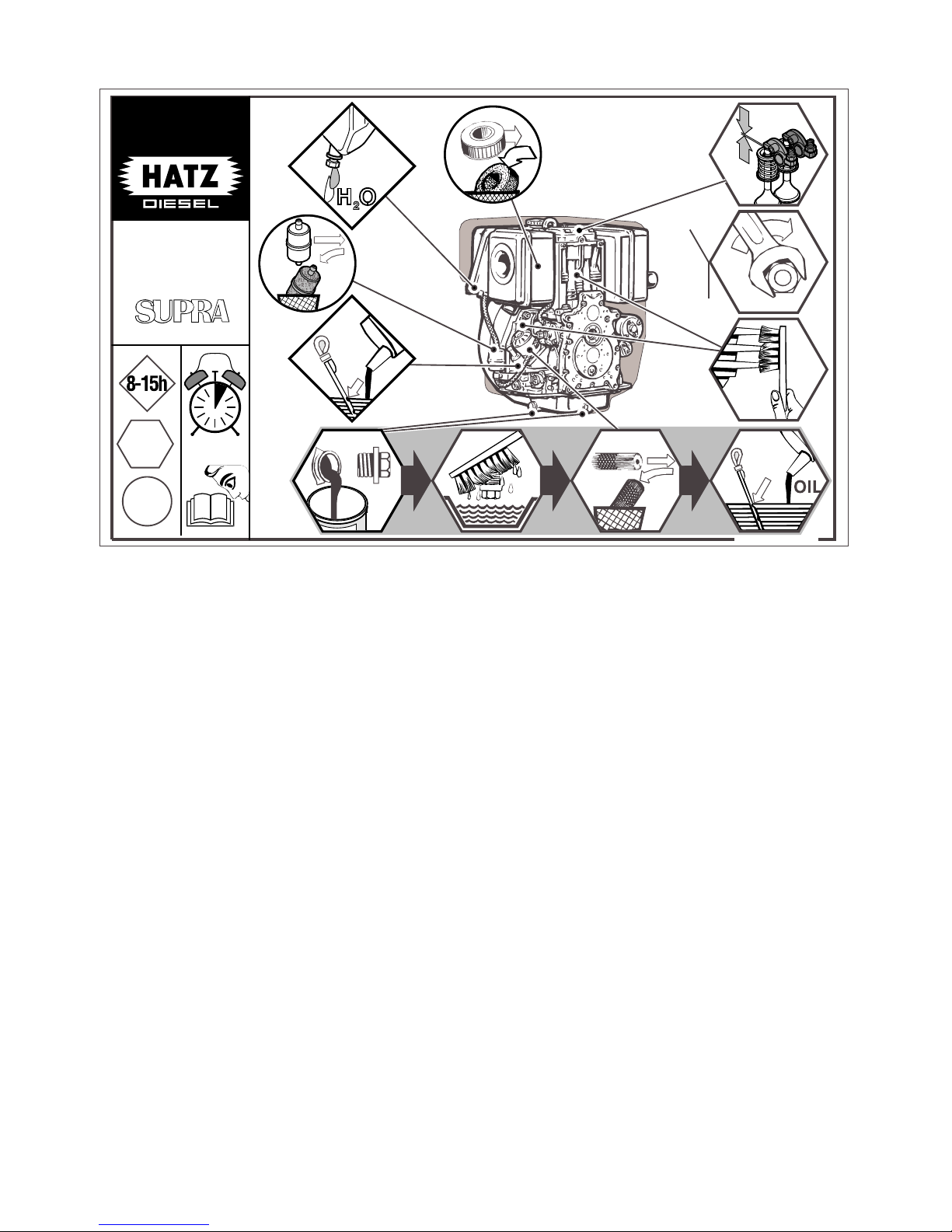
28
The above maintenance chart is supplied with
every engine. This label should be affixed to the
engine or equipment in an easily visible position.
The maintenance chart governs the maintenance
intervals.
For new or reconditioned engines, the following
must always be carried out after first 25 operat-
ing hours:
– Replace engine oil and oil filter, chap. 5.3.2.
– Check tappet clearance, and adjust if neces-
sary, chap. 5.3.3.
– Examine screw connections, chap. 5.3.5.
Do not tighten the cylinder head fastening.
For short operating periods: replace engine oil
and oil filter after 12 months at the latest, regardless of the number of operating hours.
21
IN
EX
= 1h
1D41:
1D42:
1D50:
1D81:
1D90:
IN 0.1 mm
IN 0.1 mm
IN 0.1 mm
IN 0.1 mm
IN 0.3 mm
/
/
/
/
/
EX 0.2 mm
EX 0.2 mm
EX 0.2 mm
EX 0.2 mm
EX 0.3 mm
0000 040 483 05
1D..
500h
250h
max
OIL
max
DIESEL
 Loading...