

Hatz Diesel 1D50 S, 1D60 S, 1D80 S, 1D81 S, 1D90 S Workshop Manual
...
Workshop manual
438 202 01 - Printed in Germany
1 D . .


Foreword
1. General
Engine illustrations
Technical data
Type plate data
Lubrication oil circuit
Special tools and
workshop equipments
Jointing material / Sealing and
bonding agents
2. Additional equipments
A 01.00 Fuel
A 01.10 Fuel tank
A 01.40 Fuel feed pumps
A 02:00 Combustion air
A 02.10 Oil bath air filters
A 02.11 Dry type air filters
A 02.13 Service indicators;
vacuum gauges
A 02.20 Pre-cleaners; cyclons
A 03.00 Exhausts
A 03.12 Exhaust-silencers,
Protection guard
A 04.00 Start mechanical
A 04.10 Starting handles
without supports
A 04.11 Starting handle supports
A 04.12 Cranking claws
A 04.30 Rope starts
A 05.00 Start electrical
A 05.20 Starter motors
A 05.40 Alternator / Magnet segments
A 05.41 Alternator / Coils
A 05.80 Ring gears
A 07.00 Lubrication oil
A 07.20 Lub.-oil filters, strainers
A 07.30 Oil sumps
A 09.00 Speed controls
A 09.60 Low idle speed stabilization
A 11.00 Remote engine controls
A 11.10 Stop devices
A 11.30 Auto. Shut-off device
A 15.00 Housings, flanges,
adaptors
A 15.20 Adaptor housings
Contents

3. Basic engine
M–Disassembly cross reference scheme
M 01.00 Crankcase
M 01.10 Crankcase, nozzle
and bearings
M 01.11 Plugs
M 01.20 Crankshaft-thrustplate
and cam followers
M 01.30 Oil sump and suction sieve
M 01.31 Oil sump 1 D 50
M 01.40 Base plate and
oil pressure relief valve
M 01.50 Cyl.-head screw sealants
M 02.00 Crankshaft
M 02.10 Wear and grinding dimensions
M 02.20 Crankshaft gearwheel and
stubshafts
M 02.30 Crankshaft / Wear sleeve
M 03.00 Bearing flange
M 03.10 Bearing flange 1D 90 V/W
M 04.00 Camshaft and balancer unit
M 05.00 Piston with connecting rod
M 05.10 Piston and piston rings
M 05.20 Connecting rod
M 06.00 Cylinder
M 07.00 Cylinder head
M 07.10 Rockers and decompression
device
M 07.20 Bumping clearance
M 07.30 Cyl.-head and oil supply pipe
M 07.40 Valves, valve guides and
valve seats
M 08.00 Cover for cylinder head
M 09.00 Pushrods / Protection tubes
M 10.00 Oil pump / Governor
M 11.00 Timing cover
M 12.00 Extra fuel device
M 14.00 Fuel-injection equipment
M 14.10 Fuel pressure pipe
M 14.20 Injector
M 14.30 Injection pump
M 14.40 Roller tappet
M 17.00 Flywheel
M 26.00 Cowling / Air duct
M 31.00 Breather system
M 32.00 Speed control
M 35.00 Capsule
4. Data sheets
Injection equipment adjustment data
Governor equipment
General adjustment and testing data
Screw tightening torques
Designations in circuit diagrams
HATZ wiring designations
Electrical circuit diagrams
Circuit diagram for measuring
currents and voltages
Generator output characteristic
Troubleshooting – electrical system
Contents

Foreword
This Workshop Manual covers the latest technical developments according to
month/year indicated on each page. It has been written in such a way, that it contains all
dismantling and assembly instructions in accordance with the table of contents, including all required data etc., so as to permit a trained mechanic to carry out correct and
professional repairs.
We have not included information such as cleaning parts, replacing of "O" Rings,
gaskets, oil seals etc. since it is assumed, of course, that the mechanic will be aware of
the necessity of carrying out such work.
Use only the tools prescribed or absolutely identical tools when carrying out work of
whatever nature.
It has been assumed that a standard set of workshop tools is available.
Please refer to the instruction book for maintenance work, operating materials and trouble shooting information.
Use only GENUINE HATZ PARTS for repairs!
Only these parts guarantee perfect dimensional accuracy and quality.
For the rest, please observe the general legal regulations and the regulations of the responsible professional associations.
Discrepancies may occur between the described features and actual features owing to
special equipment, and it has not been possible to allow for such discrepancies either in
the Workshop Manual or in the spare parts list.
Should you have any difficulties, please contact your nearest HATZ-Service agent.


1
1D . . / 03.06
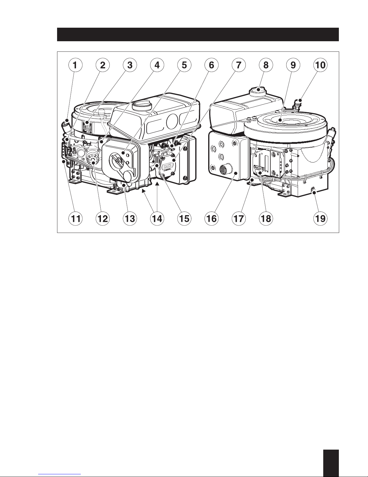
1. General
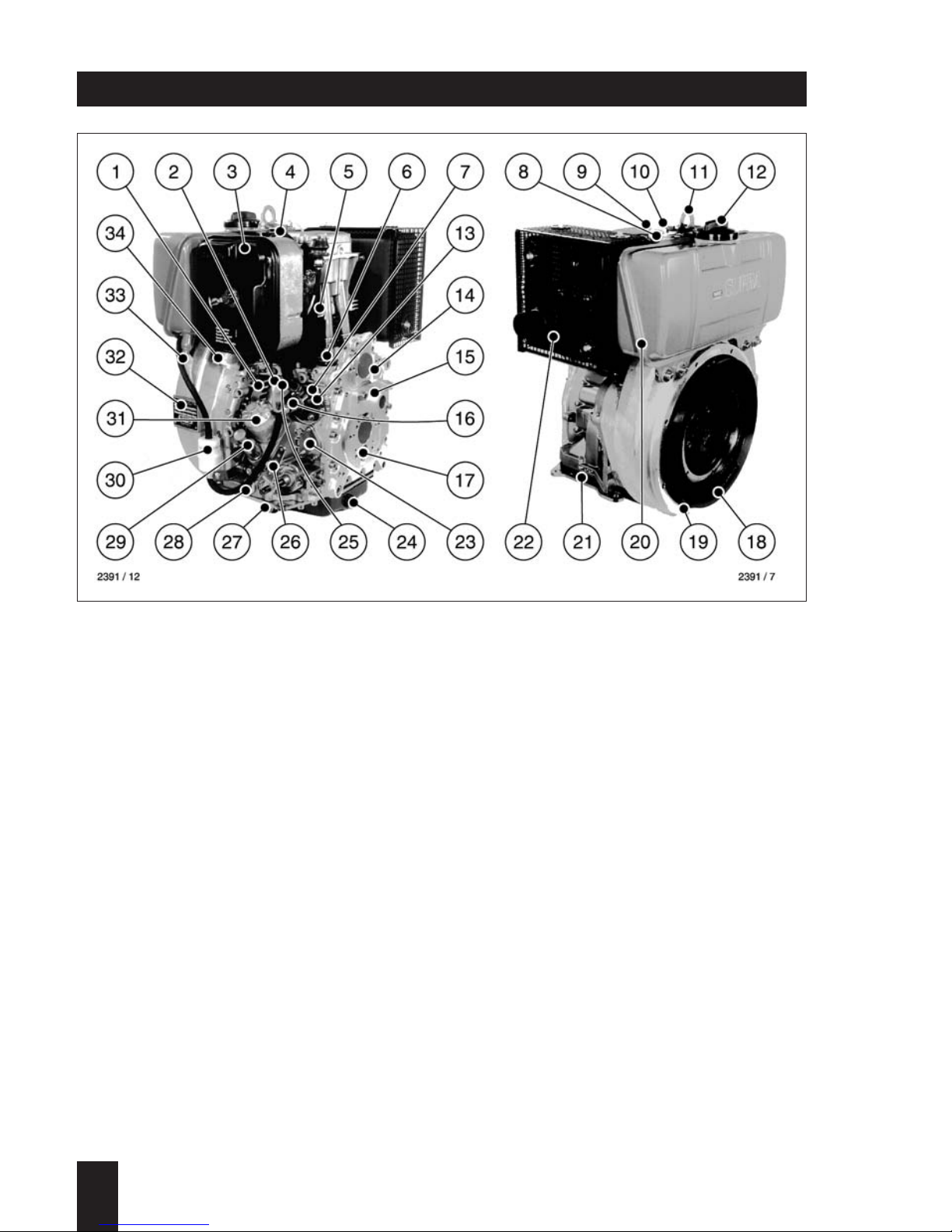
1 Cooling air inlet
2 Oil pressure switch
3 Dry type air cleaner
4 Decompression lever
5 Cooling air outlet
6 Extra fuel device
7 Injection pump
8 Injector
9 Cylinder head cover
10 Cold start-oil priming device
11 Lifting bracket, max. 120 kg / 265 lb
12 Fuel filler cap
13 Stop lever
14 Timing cover
15 Guiding shell for starting handle
16 Fuel pressure pipe
17 Governor
1
1D . . / 03.06
18 Flywheel
19 Engine flange
20 Fuel tank
21 Engine base plate
22 Exhaust silencer
23 Fuel feed pump (mounting pos.)
24 Oil drain plug, governor side
25 Injection pump bleeder valve
26 Speed control lever
27 Oil drain plug, control side
28 Oil pressure relief valve
29 Oil filling hole and dipstick
30 Fuel filter
31 Oil filter (optional)
32 Type plate
33 Fuel tank drain plug
34 Combustion air intake
Engine illustrations
Engine 1D30, 1D31, 1D40, 1D41, 1D50, 1D60, 1D80, 1D81, 1D90 S/Z/T/U
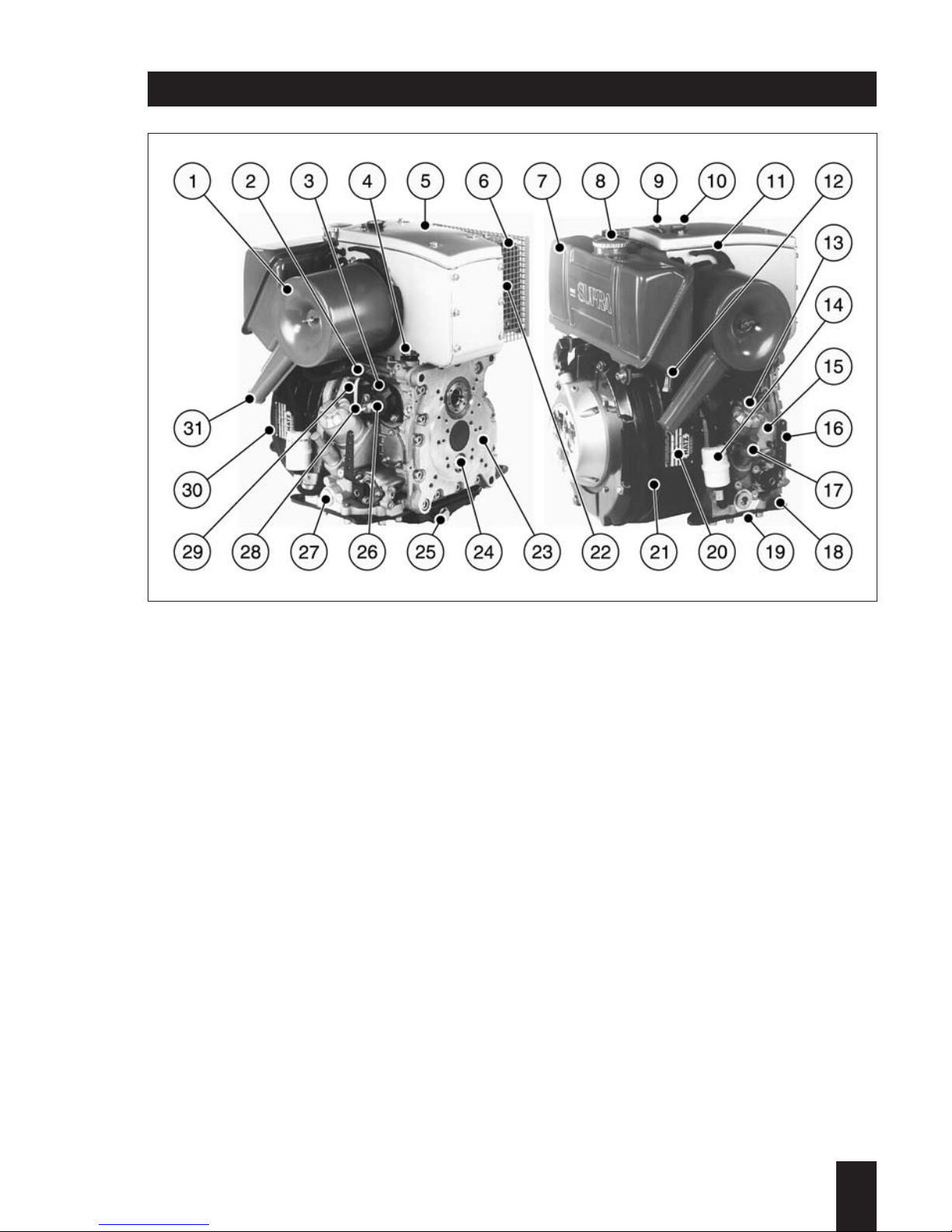
16 Speed control lever
17 Oil filling hole and dipstick
18 Engine base plate
19 Oil drain plug, control side
20 Type plate
21 Engine flange
22 Cooling air outlet
23 Timing cover
24 Governor
25 Oil drain plug, governor side
26 Injection pump
27 Oil pressure relief valve
28 Fuel pressure pipe
29 Cooling air inlet
30 Flywheel
31 Combustion air intake
1
1D . . / 03.06
1 Air filter
2 Oil pressure switch
3 Injection pump bleeder valve
4 Extra fuel device
5 Air cowling cover
6 Exhaust silencer
7 Fuel tank
8 Fuel filler cap
9 Lifting bracket, max. 120 kg / 265 lb
10 Cold start-oil priming device
11 Decompression lever
12 Fuel tank drain plug
13 Oil filter (optional)
14 Fuel filter
15 Fuel feed pump (mounting pos.)
Engine illustrations
Noise-optimized version
Engine A1D35, A1D40, A1D41 S/Z/T/U
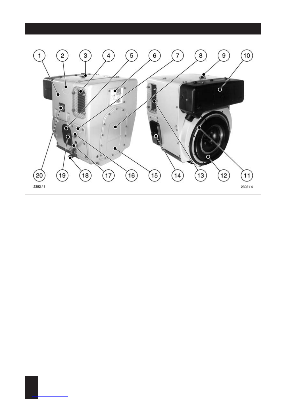
1 Capsule
2 Decompression lever
3 Cold start-oil priming device
4 Combustion and cooling air intake
5 Oil filter
6 Cleaning opening
7 Side panels
8 Access for starting handle
9 Lifting bracket, max. 120 kg / 265 lb
10 Exhaust silencer, enclosed
11 Engine flange
1
1D . . / 03.06
12 Flywheel
13 Cooling air outlet
14 Battery connections and central plug
for electrical system
15 Access to timing cover
16 Stop lever
17 Speed control lever
18 Oil drain plug
19 Oil filling hole and dipstick
20 Type plate
Engine illustrations
Fully encapsulated version
Engine 1D30C, 1D31C, 1D40C, 1D41C, 1D60C, 1D80C, 1D81C
1 oil filler cap
2 dipstick
3 type plate
4 combustion air intake
5 dry type airfilter
6 fuel tank drain plug
7 cylinder head cover
8 fuel filler cap
9 cooling air inlet
10 mechanical maintenance indicator
11 speed control lever
12 oil filter
13 fuel filter
14 cooling air outle
15 decompression levert
16 exhaust silencer
17 electric starter
18 central plug f. electrical equipment
19 oil drain plug
Engine illustrations
Engine 1D90 V/W
1
1D . . / 03.06

1
1D . . / 03.06
Type 1D30.. 1D40.. A1D35..
1D31.. A1D40..
Engine models S, Z, T, U, C S, Z, T, U, S, Z, T, U
Mode of operation Air-cooled four-stroke diesel engine
Combustion method Direct-injection
Number of cylinders 1 1 1
Bore / stroke mm 86/65 86/65 86/65
Cubic capacity cm
3
377 377 377
Compression ratio 1D30: 20.5:1 20.5:1 20.5:1
1D31: 21.0:1 22.0:1*
Direction of rotation 1D . . S / Z / C counter-clockwise
looking at the flywheel 1D . . T / U clockwise
Cooling air required
at 3000 min
-1
m3/min 6.0 6.0 6.0
Combustion air required
at 3000 min-1 m3/min 0.56 0.56 0.56
Oil capacity without oil filter approx. 1.1 1.1 1.1
with oil filter ltr. 1.2 1.2 1.2
Difference between approx. 0.4 0.4 0.4
„max“ and „min“ markings ltr.
Oil consumption Approx. 1% of fuel combustion at full load
Max. permissible inclination approx. 30° approx. 30° approx. 30°
in each direction during operation
Net weight
Engine models S, Z, T, U approx. 68 68 74
Engine models C kg 89 89 –
Model S: non-encapsulated, normal system of balancing, counter-clockwise rotation
Z: non-encapsulated, add. system of balancing, counter-clockwise rotation
T: non-encapsulated, normal system of balancing, clockwise rotation
U: non-encapsulated, add. system of balancing, clockwise rotation
C: SILENT PACK, add. system of balancing, counter-clockwise rotation
*Engines in connection with compaction units
Technical data

1
1D . . / 03.06
Type 1D41.. 1D50.. 1D60..
A1D41..
Engine models S, Z, T, U, C S, Z S, Z, T, U, C
Mode of operation Air-cooled four-stroke diesel engine
Combustion method Direct-injection
Number of cylinders 1 1 1
Bore / stroke mm 90/65 97/70 88/85
Cubic capacity cm
3
413 517 517
Compression ratio 20.0:1 20.0:1 20.5:1
Direction of rotation 1D . . S / Z / C counter-clockwise
looking at the flywheel 1D . . T / U clockwise
Cooling air required
at 3000 min-1 m3/min 6.0 6.0 10.5
Combustion air required
at 3000 min-1 m3/min 0.62 0.78 0.78
Oil capacity without oil filter approx. 1.1 1.4 1.8
with oil filter ltr. 1.2 1.5 1.9
Difference between approx.
„max“ and „min“ markings ltr. 0.4 0.5 0.9
Oil consumption Approx. 1% of fuel combustion at full load
Max. permissible inclination
in each direction during operation approx. 30° approx. 30° approx. 30°
Net weight
Engine models S, Z, T, U approx. 68* 76 91
Engine models C kg 89 – 114
Model S: non-encapsulated,normal system of balancing,counter-clockwise rotation
Z: non-encapsulated, add. system of balancing, counter-clockwise rotation
T: non-encapsulated, normal system of balancing,clockwise rotation
U: non-encapsulated,add. system of balancing, clockwise rotation
C: SILENT PACK, add. system of balancing, counter-clockwise rotation
*A1D41: 74 kg
Technical data

1
1D . . / 03.06
Technical data
Type 1D80.. 1D90.
1D81..
Engine models S, Z, T, U, C S, Z, V, W
Mode of operation Air-cooled four-stroke diesel engine
Combustion method Direct-injection
Number of cylinders 1 1
Bore / stroke mm 100/85 104/85
Cubic capacity cm
3
667 722
Compression ratio 20.5:1 20.5:1
Direction of rotation 1D . . S / Z / C / V / W counter-clockwise
looking at the flywheel 1D . . T / U clockwise
Cooling air required
at 3000 min-1 m3/min 10.5 10.5
Combustion air required
at 3000 min-1 m3/min 1.0 1.1
Oil capacity without oil filter approx. 1.8 1.8
with oil filter ltr. 1.9 1.9
Difference between approx.
„max“ and „min“ markings ltr. 0.9 0.9
Oil consumption Approx. 1% of fuel combustion at full load
Max. permissible inclination
in each direction during operation approx. 30° approx. 30°
Net weight
Engine models S/Z/T/U/V/W approx. 91 92
Engine models C 121 –
Model S: non-encapsulated, normal system of balancing, counter-clockwise rotation
Z: non-encapsulated, add. system of balancing, counter-clockwise rotation
T: non-encapsulated, normal system of balancing, clockwise rotation
U: non-encapsulated, add. system of balancing, clockwise rotation
C: SILENT PACK, add. system of balancing, counter-clockwise rotation
V: vertical crankshaft, non-encapsulated, normal system of balancing,
counter-clockwise rotation
W: vertical crankshaft, non-encapsulated, add. system of balancing,
counter-clockwise rotation
1
1D . . / 03.06
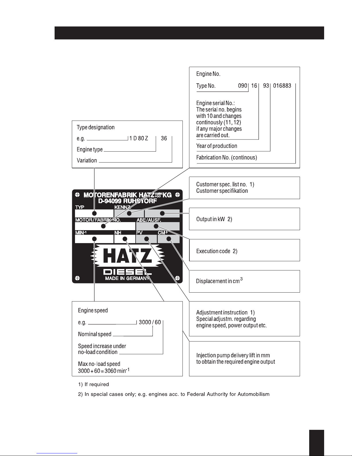
Type plate data
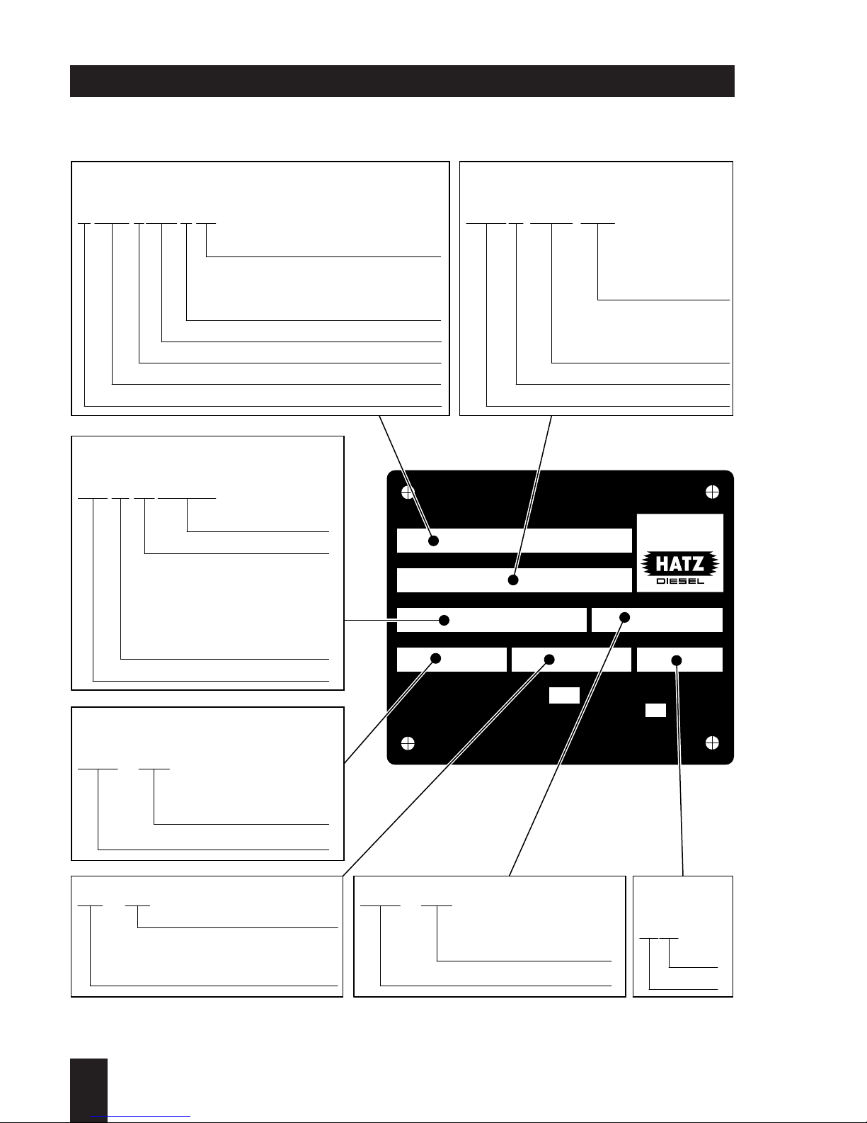
EPA / Carb type plate data
ENG.FAM.
TYPE / SPEC. / FDT
MIN
SERIAL NO.
NH / kW
-1
MOTORENFABRIK HATZ KG·D-94099 RUHSTORF
CM3 / PV
BUILD DATE
IMPORTANT ENGINE INFORMATION
This engine conforms to MY U.S. EPA regulations large
nonroad compression-ignition engines and MY California
regulation for off-road compression-ignition engines.
Refer to owner's manual
for maintenance specifications and adjustments.
VARIABLE SPEED
GMBH
CO
+
Made in Germany
0.98 10.4 0667 189A
0504
1D81 Z 216B 13.04 HZX L.667 V 83
2950 290
073 23 04 083019
Rated power in kW
Injection pump delivery lift
in mm to obtain the required
power output
Special adjustment
instruction
Displacement in cm
3
Year
Month
Variation
Customer specification
(only for special
equipment)
Engine type
Static timing
(begin of fuel
delivery)
V = variable speed application
C = constant speed application
A = V + C as well
Displacement (in cm
3
or liters)
Diesel engine (Benzin/gasoline = S)
Manufactorer HZX = HATZ
Manuf. year (X = 1999, Y = 2000, 1 = 2001,...)
Type code
Speed increase under
no-load condition
Nominal speed
Engine serial No.:
The serial No. beginns
with 10 and changes
continously if any major
changes are carried out
Year of production
Type No.
Fabrication No.
Manuf. year
Type / Spec./ FDTEngine family
Engine speed
Engine number
1
1D . . / 03.06
1
1D . . / 03.06
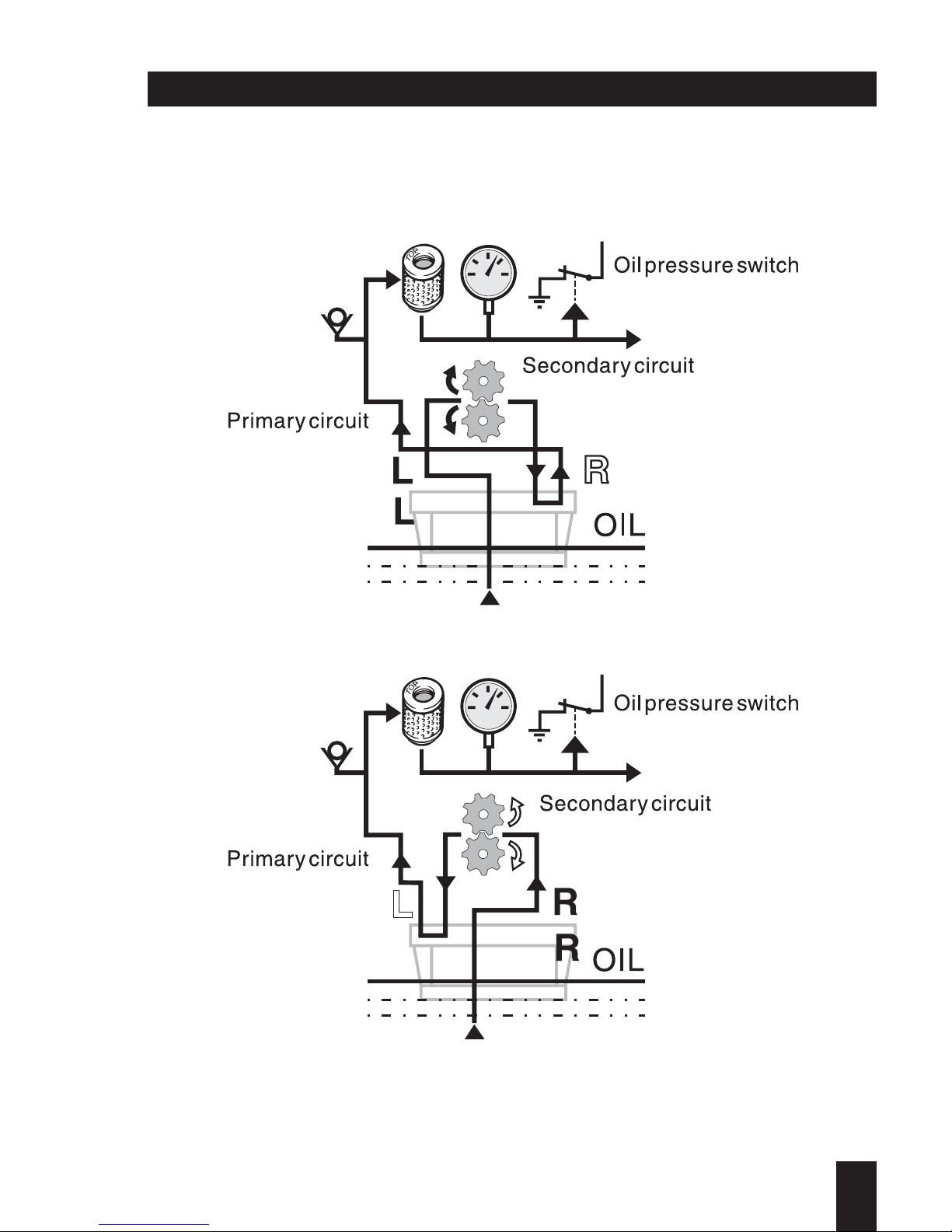
Lubrication oil circuit

1
1D . . / 03.06
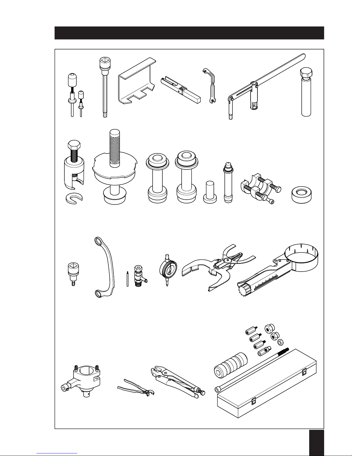
Special tools and workshop equipments
Engine series 1 D . . (SUPRA)
Bezeichnung
Verwendung
bei Typen
30-50 60-90
1
2
3
3
4
5
6
7
8
9
9
10
11
11
12
13
14
15
16
17
18
18
19
20
21
22
23
24
25
644 345 90
630 815 00
629 301 00
629 102 00
627 501 00
632 579 00
629 223 01
631 392 00
603 823 91
629 016 02
629 298 02
627 496 02
627 398 02
629 299 02
629 284 00
627 494 00
634 147 00
627 495 02
627 500 00
631 133 01
665 030 91
625 401 90
612 087 00
612 090 01
626 383 00
639 477 00
636 421 00
640 564 00
626 753 91
Clip tool for lead plugs
Allen socket 6 mm lg 1/2"
Clamp for pushrod tube
Clamp for pushrod tube
Retainer for governor spring
Adjustment wrench
Valve lifter
Mandrel for valve stem seal cap
Multi-purpose extractor
Punch for main bearing gov.-side
Punch for main bearing gov.-side
Punch for outer camshaft bushing
Punch for main bearing flywheel side
Punch for main bearing flywheel side
Heating insert for gear/stubshaft
Drift punch for camshaft bushing
Comb. extractor f. gear + stubshaft
Assembly device for oil pump shaft
Torx-socket TX 30 – 1/2"
Ring spanner 18 x 19 for starter
Spill device for injection pump M18x1.5
Spill device for injection pump M20x1.5
Dial gauge – 1/100 mm
Piston ring pliers
Piston ring clamp.device ∅ 70-100 mm
Measuring device for injection pump
Pliers for EPA - radial (tamper-resistant)
Pliers for EPA - axial (tamper-resistant)
Impact hammer with fittings
xx
xx
x–
–x
xx
xx
xx
xx
xx
–x
x–
xx
–x
x–
xx
xx
xx
xx
xx
xx
xx
xx
xx
xx
xx
xx
xx
xx
xx
Ident-Nr.Nr.
1
1D . . / 03.06
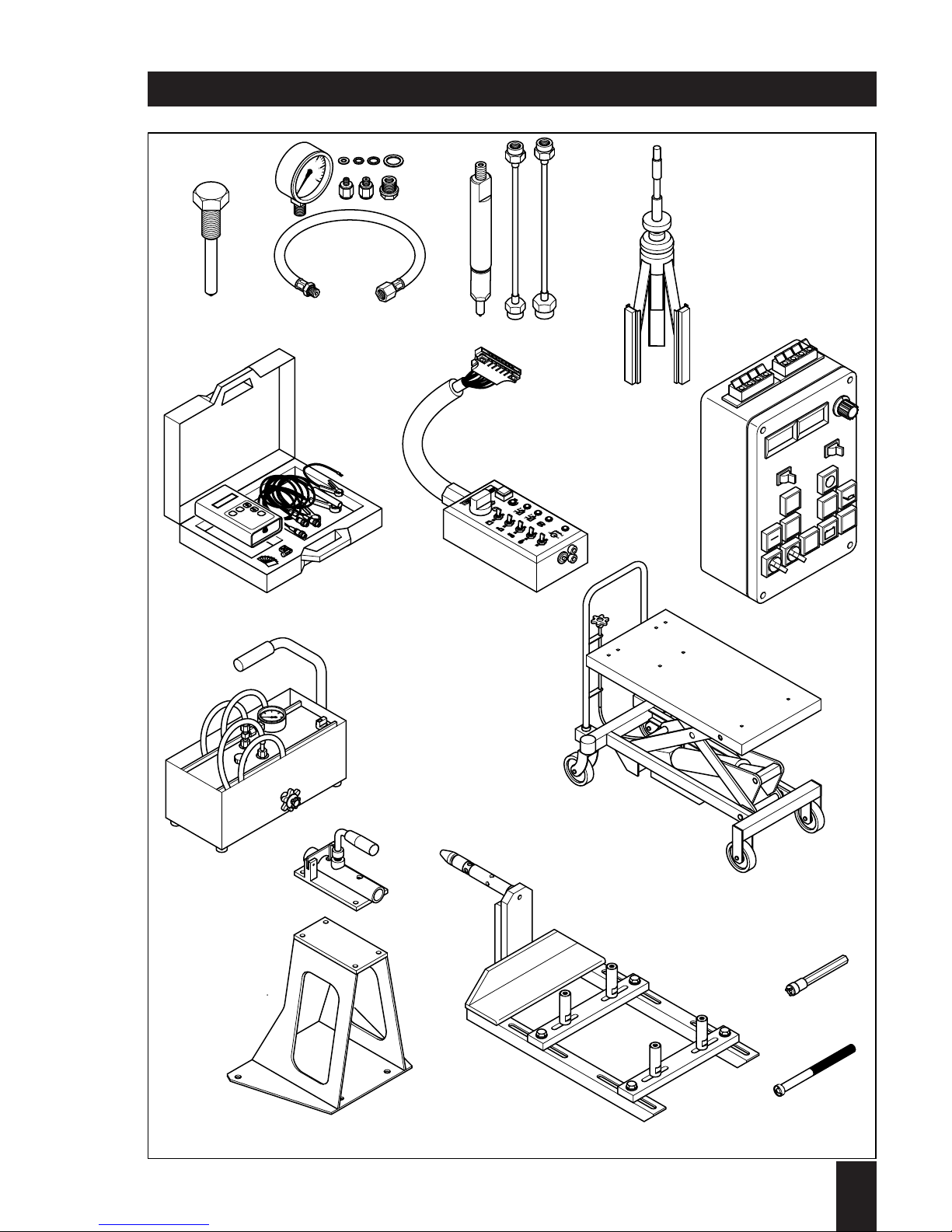
Special tools and workshop equipments
2
345 6 7
8 9 10 11 12 13 14 15
16 17
1
9
1
8
18 19 20 21
22 23 24 25
1

Engine series 1 D . . (SUPRA)
Special tools and workshop equipments
1
1D . . / 03.06
Nr.
Bezeichnung
Verwendung
bei Typen
30-50 60-90
26
27
28
29
30
31
32
33
34
35
36
37
38
39
633 013 00
620 926 92
630 094 90
634 142 00
624 838 92
641 610 90
633 178 00
632 913 00
624 863 02
625 682 01
625 751 90
631 300 00
644 991 01
645 020 00
Forcing screw for centrif.-clutch
Oil pressure gauge 0... 6 bar
Test nozzle 400 bar / 5800 psi
Honing tool
Rev.-counter for fuel press.-pipe
Testbox for instrument box
Components testbox
High-pressure supply pump
Hydraulic lift trolley
Revolvable fixing - basic part
Console for revolvable fixing
Revolvable fixing - adaptor engine side
Socket wrench for lock nut
Punch for tab washer
xx
xx
xx
xx
xx
xx
xx
xx
xx
xx
xx
xx
xx
xx
Ident-Nr.
1
1D . . / 03.06
Special tools and workshop equipments
26
27
1
2
3
5
6
4
0
28
29
31
30
#
*
ON
15
86
87a
50
87
STAR
- +
32
34
33
10
20
30
40
max. 750 kg
35
36
37
39
38

1
1D . . / 03.06
Jointing material / Sealing and bonding agents
Sealing and bonding agents are available from HATZ for use in maintenance and/or repair works.
All items listed below may be ordered as individual spare parts.
Refer to appropriate spare parts list for ordering.
Application of sealing and bonding agents:
The letter coding in the drawings indicates which agents should be applied when fitting
the part refered to.
See the following list for decoding the material; this list is the same as already being
used with all other service literature including spare parts list.
A = 502 230 01 Loctite Activator 500 ml
B = 502 231 00 Loctite 573 50 ml
C = 502 232 00 Loctite 601 50 ml
D = 502 233 00 Loctite 221 50 ml
E = 502 234 00 Loctite 648 10 ml
F = 502 238 00 Technicoll 8058 750 g
+ 502 239 00 Technicoll 8367 750 g
G = 502 565 01 Loctite IS 407 20 g
H = 502 825 01 Silicon sealer 30 ml
J = 502 830 02 Anti-Seize compound 1000 g
K = 503 426 00 High-temp. lub.-grease 100 g
L = 502 566 00 Silicon sealer 100 g
M = 504 851 00 Polishing paste K 240 80 ml

2
1D . . / 03.06
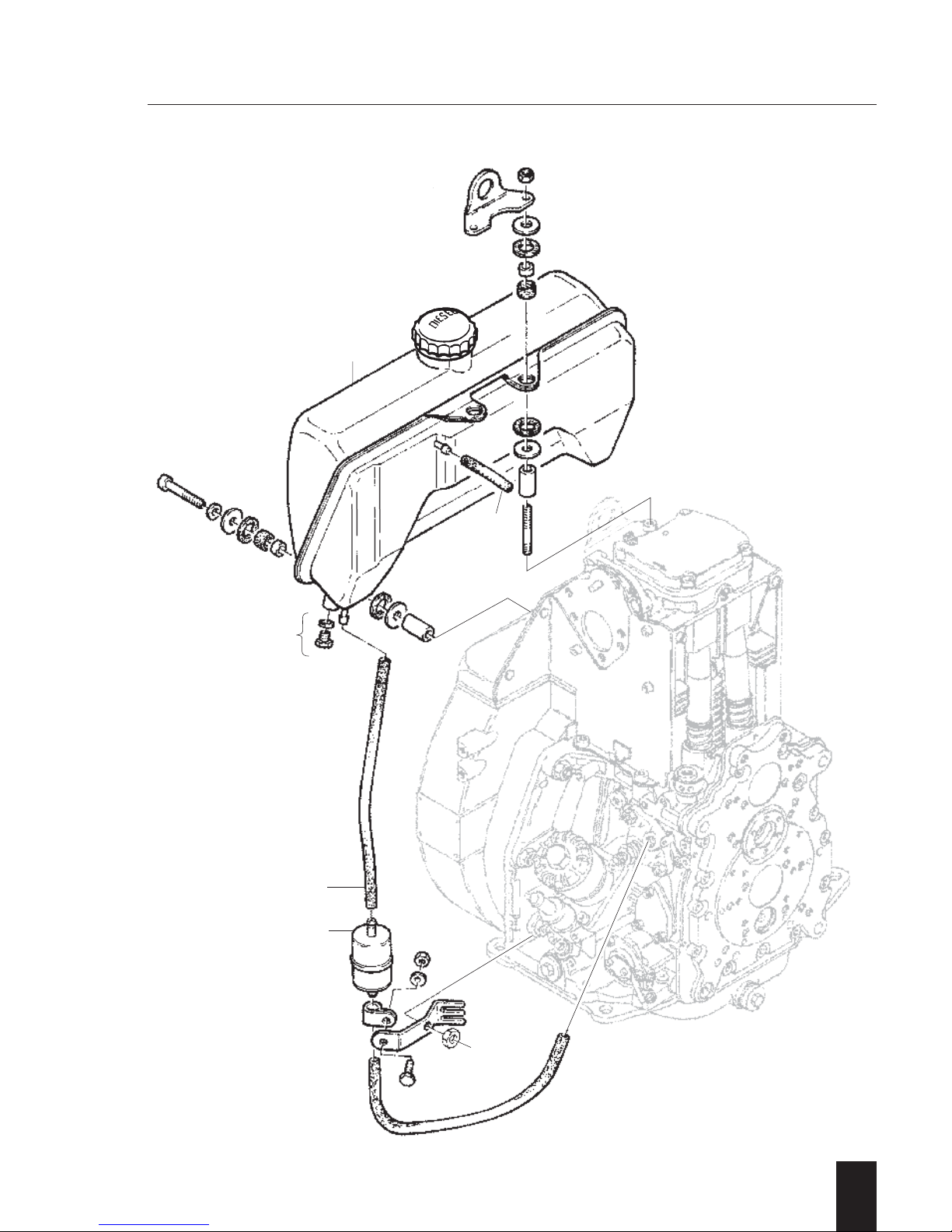
2. Additional equipment

A 01.10 Fuel tank
–
Preparations: –
Dismantling:
– Loosen drain plug 1 and drain off fuel or
close off fuel supply pipe 2.
– Remove (pull off) fuel hoses 2...3 from
fuel filter and fuel tank.
– Unscrew respectively remove all retaining
components in question, including fuel
tank 4.
– Remove fuel filter 5 with retaining compo-
nents if necessary.
Inspection / repair:
– Visual inspection.
– Check fuel tank for cracks and/or any
other damage.
– Check all rubber parts for ageing etc.
Maintenance according to instruction book!
Assembly:
– Re-assemble and re-connect fuel tank 4
and fuel filter 5 as well as fuel hoses 2...3.
Tighten all retaining items uniformly to
obtain a stress free assembly of the fuel
tank.
– Remove clamp tool and/or tighten drain
plug 1.
2
1D . . / 03.06
A 01.00 Fuel
A 01.00
A 01.10
2
1D . . / 03.06
4
3
2
5
1

2
1D . . / 03.06
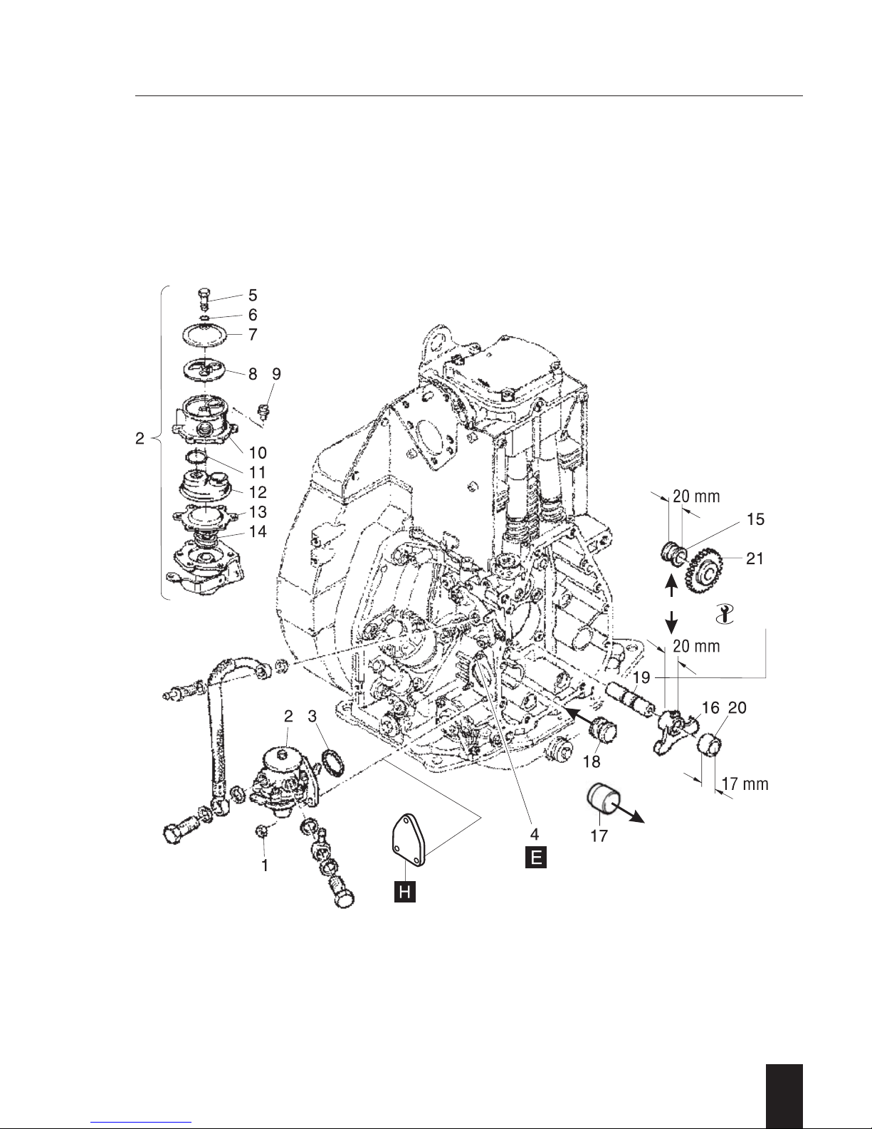
A 01.40 Fuel feed pumps
- 25 -
I. Fuel feed pump
General:
When connecting the fuel feed pump take
care for arrangement of suction and supply
hose.
Preparations:
– Disconnect fuel supply from fuel feed and
injection pump.
Dismantling:
– Remove in numerical sequence 1 ... 3.
NOTE:
When removing the upper nut, make sure
that the stud 4 does not turn in the crankcase as it serves as the anchor pin for the
governor lever retainer spring. If turning of
the stud cannot be avoided, remove the
spring from the pin. The front cover must be
removed to remove the spring.
Ref.: Chapt. M 11.00
Inspection / repair:
– Visual inspection.
For further repair proceed as follows:
– Remove in numerical sequence 5 ... 14.
Required only if irregularities such as poor
suction / pumping action i.e. contaminated
strainer or leaks have been noted.
– Check and replace all parts in question.
Assembly:
– Pre-assemble in reverse sequence 14...5.
– Assemble in reverse sequence 3 ... 1.
– Ensure actuating lever 16 is in bottom
position and „O“-Ring 3 remains in its
groove when assembling.
– After installation and a short test run,
check the fuel system for leaks.
II. Fuel feed pump drive
General:
Models Z/U/C
Bushing 15 is replaced by the actuating
lever 16.
Models S/T
Plug 17 is replaced by the plug 18 with
ring groove.
Preparations:
– Remove fuel feed pump.
– Remove timing cover.
Ref.: Chapt. M 11.00
Dismantling:
– Remove part 20/21 and lever 16.
– Remove shaft 19.
For removal use tool - 25 -
Plug 18 remains in crankcase.
Inspection / repair:
– Visual inspection.
– Check parts for wear and/or any other
damage.
Assembly:
– Assemble in reverse sequence .
– Press in shaft 19 to a protrusion of 52 ±
0,5 mm.
Extractor thread must face front!Models
Z/U/C
Ensure all gear timing marks match!
– Finish assembling.
A 01.00 Fuel
2
1D . . / 03.06
A 01.00
A 01.40
25

2
1D . . / 03.06
A 02.10 Oil bath air filters
–
General:
The oil bath air filter is fitted by means of an
intermediate flange which adapts from the
triangle-type flange at cylinder head to the
twin-screw flange of oil bath air filter. This
flange also holds the glow plug in case a
pre-heating system is fitted.
Preparations: –
Dismantling:
– Disconnect cable connection from glow
plug if fitted.
– Remove in numerical sequence 1...9.
Studs and Hex.-head screw plug or glow
plug may remain.
Don't tip oil bath air filter !
Inspection / repair:
– Visual inspection.
– Check air filter body for cracks and/or any
other damage.
Maintenance according to instruction book!
NOTE:
Never „repair“ an oil bath air filter by
welding/soldering etc.
It causes total damage to the part and may
lead to engine failure!
Assembly:
– Assemble in reverse sequence 9...1.
Ensure the correct amount of gaskets
are used and parts seal properly to
avoid infiltrated air.
When fixing the oil bath air filter take
care for correct position of kidneyshaped washers 3, convex side faces
retaining nuts 1.
– Reconnect cable connection to glow
plug if so fitted.
A 02.00 Combustion air
2
1D . . / 03.06
A 02.00
A 02.10
78
6
3
12
4
9
5

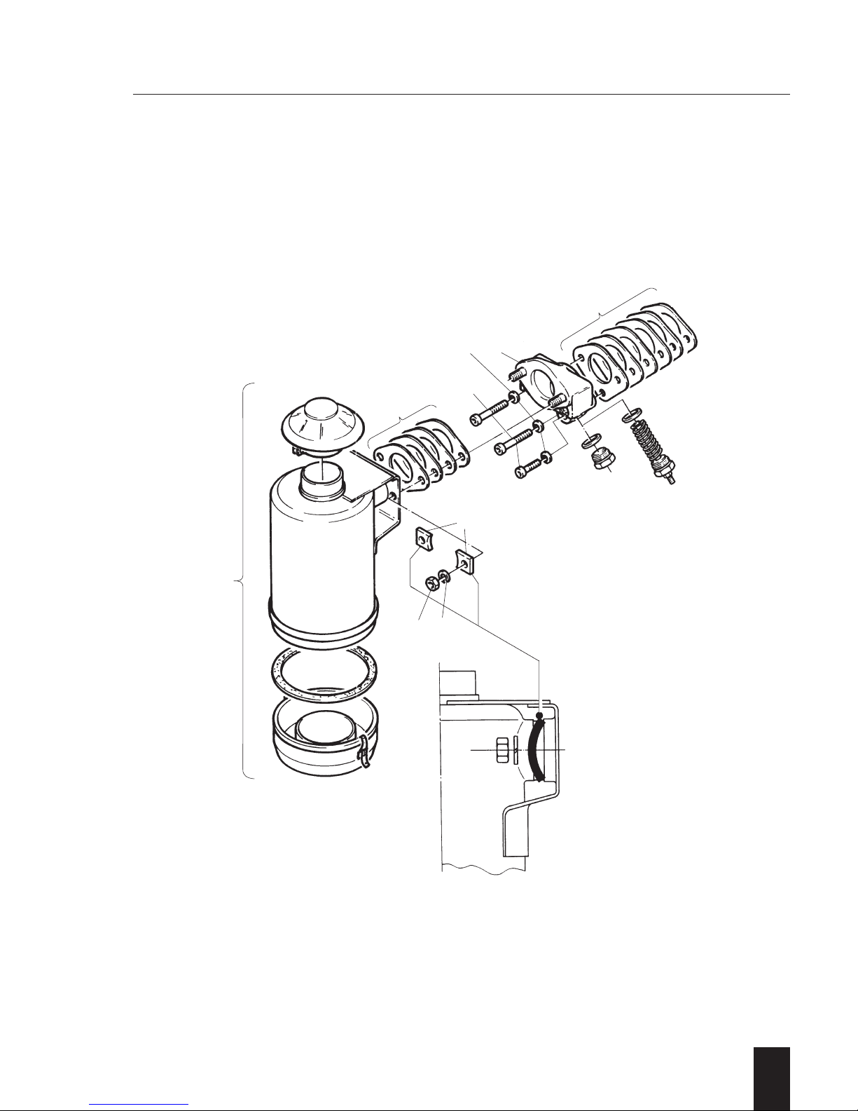
A 02.11 Dry type air filters
–
Version A 02.11.1
Fixation of filter element and cover by flat
washers and Hex.-nuts.
Preparations: –
Dismantling:
– Remove in numerical sequence 1...10.
Inspection/repair:
– Visual inspection.
– Check filter element 6 and sealing strip
around cover 3.
Maintenance according to instruction book!
Assembly:
– Assemble in reverse sequence 10...1.
Torque to specification!
NOTE:
Mind total length of bushing 4 and washer 5
respectively length of bushing 4 without
washer.
Take care for correct position of insulating
flange in between, correct amount of
gaskets and proper sealing of all parts to
avoid infiltrated air.
Conversion:
Possible to current standard in case all parts
in question become replaced.
2
1D . . / 03.06
Version A 02.11.2
Fixation of filter element separately by
retaining plate, flat washers and Hex.-nuts.
Preparations: –
Dismantling:
– Disconnect cable connection from
heater flange if so fitted.
– Remove in numerical sequence 1...12.
– If necessary dismantle cover retaining
screw to replace sealing sleeve (rubber)
between screw cap and cover.
Inspection / repair:
– Visual inspection.
– Check filter element 6 and sealing strip
around cover 1.
Maintenance according to instruction book!
Assembly:
– Assemble in reverse sequence 12...1.
Torque to specification!
NOTE:
Take care for correct position of insulating
flange in between, correct amount of
gaskets and proper sealing of all parts to
avoid infiltrated air.
– Reconnect cable connection to heater
flange if so fitted.
Conversion:
Possible to current standard in case all
parts in question become replaced.
A 02.00 Combustion air
 Loading...