

Page 1

INSTRUCTION BOOK
433 216 08-USA-EPA IV-CARB
10.07-0.1
Printed in Germany
1D 41.
1D 50.
1D 81.
1D 90.
33
INCLUDES SUPPLEMENTAL INFORMATION TO THE
OWNER’S MANUAL FOR 2008 AND LATER EPA CERTIFIED
NONROAD COMPRESSION-IGNITION ENGINES
INCLUDES SUPPLEMENTAL INFORMATION TO THE
OWNER’S MANUAL FOR 2008 AND LATER CALIFORNIA
REGULATIONS FOR HEAVY-DUTY OFF-ROAD ENGINES
Page 2
1
A new HATZ diesel engine is ready to work for you
This engine is intended only for the purpose determined and tested by the manufacturer of the
equipment in which it is installed. Using it in any other manner contravenes the intended purpose.
For danger and damage due to this, Motorenfabrik HATZ assumes no liability. The risk is with the
user only. Use of this engine in the intended manner presupposes compliance with the maintenance
and repair instructions laid down for it. Noncompliance leads to engine breakdown.
Please study this Instruction Book before you start the engine for the first time: it will help you to
avoid accidents, to operate the engine correctly, to perform maintenance work and to keep the engine
operating at full efficiency for a very long time.
Please follow all maintenance references carefully including the schedule for 2008 and later
EPA certified nonroad compression-ignition engines and for 2008 and later CARB certified
Heavy-Duty off-road engines to prevent our environment.
Please pass this Instruction Manual on to the next user or to the following engine owner.
Throughout the world, a network of HATZ service stations is at your disposal for advice, spare parts
supply and maintenance or repair work.
Please refer to the enclosed list for the address of your nearest HATZ service point.
Please use only genuine HATZ spare parts. Only these parts guarantee a perfect dimensional stability
and quality. Their order numbers are shown in the enclosed Parts List. Please note the complete
spare part kits in Table M00 of the list.
In the interests of technical progress we reserve the right to introduce modifications.
MOTORENFABRIK HATZ GMBH & CO KG
Page 3

Page
1. Important notes on safe operation
of the engine 3
2. Description of the engine 5
3. General information 7
3.1. Technical data 7
3.2. Transport 8
3.3 Instructions for installation 8
3.4. Load on engine 8
3.5. EPA/CARB-type plates 8
3.6. Emission-related installation
instructions 9
4. Operation 10
4.1. Before initial start-up 10
4.1.1. Engine oil 10
4.1.2. Oilbath air cleaner 10
4.1.3. Fuel 11
4.1.4. Mechanical oil pressure monitor 12
4.2. Starting the engine 13
4.2.1. Preparations for starting 13
4.2.2. Starting with the handle 14
4.2.3. Starting with the handle with
kick-back damping 15
4.2.4. Starting in cold weather 16
4.2.5. Electric starter 16
4.3. Stopping the engine 18
5. Maintenance 19
5.1. Maintenace summary 19
5.2. Maintenance every 8 – 15 hours
of operation 21
5.2.1. Check engine oil level 21
5.2.2. Check air intake point 21
5.2.3. Air cleaner blockage indicator 21
5.2.4. Checking cooling air zone 22
5.2.5. Checking the water trap 22
Page
5.3. Maintenance every 250 hours
of operation 23
5.3.1. Oilbath air cleaner maintenance 23
5.3.2. Changing engine oil, renewing
oil filter 24
5.3.3. Checking and adjusting
valve clearances 25
5.3.4. Clean the cooling air system 26
5.3.5. Checking threaded connections 26
5.3.6. Cleaning mesh insert in exhaust
silencer 26
5.4. Maintenance every 500 hours
of operation 27
5.4.1. Renewing fuel filter 27
5.4.2. Dry-type air cleaner maintenance 28
6. Malfunctions – Causes – Remedies 30
7. Work on the electrical system 34
8. Protective treatment 34
SUPPLEMENTAL INFORMATION TO
THE OWNER’S MANUAL FOR 2008
AND LATER EPA CERTIFIED
NONROAD COMPRESSION IGNITION
ENGINES 35
SUPPLEMENTAL INFORMATION TO
THE OWNER’S MANUAL FOR 2008
AND LATER CALIFORNIA
REGULATIONS FOR HEAVY-DUTY
OFF-ROAD ENGINES 51
2
This symbol draws attention to important safety precautions.
Please comply with them most carefully in order to avoid any risk of injury to persons or
damage to materials.
General legal requirements or safety regulations issued by the competent authorities or
industrial accident insurers are also applicable.
Contents
Page 4

3
1. Important notes on safe operation of the engine
HATZ diesel engines are economical, strongly built and long-lasting. They are therefore frequently
chosen for commercially and industrially operated equipment and machinery.
Since the engine forms part of the finished equipment or machine, its manufacturer will take all the
applicable safety regulations into account.
Nevertheless, we give below certain additional comments on operating safety, and would recommend
you to note them carefully.
Depending on the manner in which the engine is installed and its intended application, the equipment
manufacturer or operator may have to attach additional safety devices and prohibit potentially hazardous aspects of operation, for example:
– Parts of the exhaust system as well as the surface of the engine are of course hot during operation
of the engine, but also when it is still cooling down after use, and must not be touched.
– Faulty wiring or incorrect operation of electrical equipment may lead to sparks forming, and must
be avoided as a potential fire hazard.
– Rotating parts must be shielded against accidental contact when the engine is installed in other
equipment or machinery.
Guards are available from HATZ to protect belt drives, cooling fans and generators.
– Before attempting to start the engine it is essential to have studied the starting information in the
Instruction Book; this is particularly important on engines started with a starting handle.
– Mechanical starting devices must not be used by children or persons of insufficient physical
strength.
– In order to benefit from the advantages of the starting handle with kick-back damping, it must be
used precisely as recommended in this Instruction Book.
– Before starting the engine, ensure that all the specified protective guards are in place.
– The engine must only be operated, serviced or repaired by persons who have received the appro-
priate training.
– Keep the starting handle and the key out of reach of unauthorized persons.
– Never run the engine in closed or badly ventilated rooms.
Do not breath in emissions - danger of poisoning!
– Also fuel and lubricants could contain poisonous components. Please follow the instructions of the
mineral oil producer.
Page 5

4
Important notes on safe operation of the engine
– Stop the engine before performing any maintenance, cleaning- and repair work.
– Stop the engine before refuelling.
Never add fuel near a naked flame or a source of sparks.
Don’t smoke. Don’t spill fuel.
– Keep explosive materials as well as flammable materials away from the engine because the exhaust
gets very hot during operation.
– Wear close-fitting clothing when working on a running engine.
Please don’t wear necklaces, bracelets or any other things which you could get caught with.
– Please pay attention to all advice- and warning stickers placed on the engine and keep them in legi-
ble condition. Contact your next HATZ service station, if a sticker comes off or is illegible and ask
for a new one.
– Note that any unauthorized modification to the engine absolves its manufacturer from liability for
the consequences.
Regular servicing in accordance with the details provided in this Instruction Book is essential to keep
the operating reliably and to ensure the exhaust quality of the engine.
In case of doubt, always consult your nearest HATZ service station before starting the engine.
Page 6
5
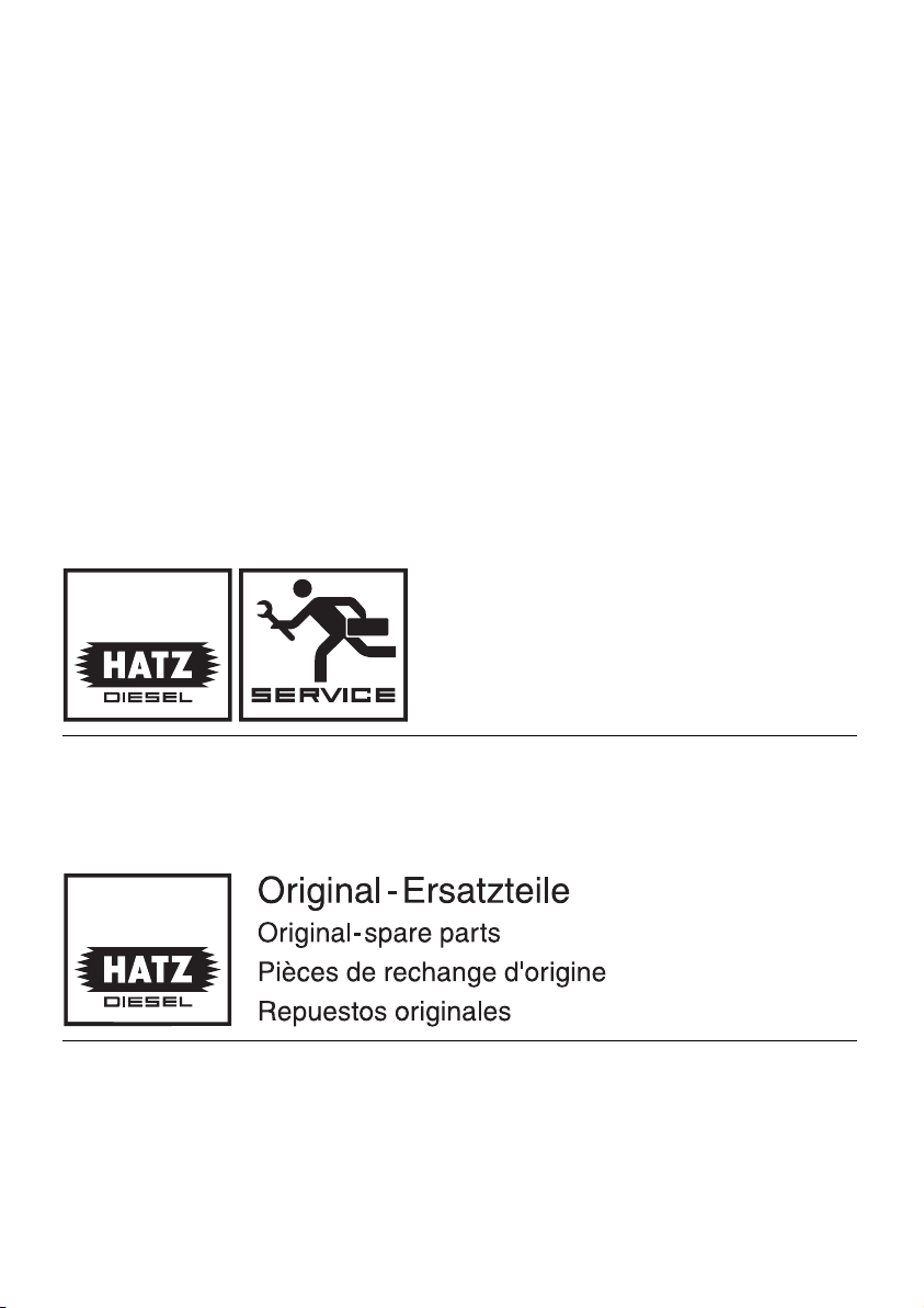
2. Description of engine
1D41 • 1D50 • 1D81 • 1D90 S / Z engines
1
2391 / 12 2391 / 7
1 Cooling air inlet
2 Dry-type air cleaner
3 Decompression lever
4 Stop lever
5 Cooling air outlet
6 Silencer (muffler)
7 Guide sleeve for starting handle
8 Cylinder head cover
9 Cold-start oil metering device
10 Suspension lug
11 Tank filler cap
12 Oil drain plug, governor housing
13 Oil drain plug, governor side
14 Speed control lever
15 Oil filler pipe and dipstick
16 Fuel filter
17 Oil filter
18 Type plate
19 Tank drain plug
20 Combustion air intake
Page 7
6
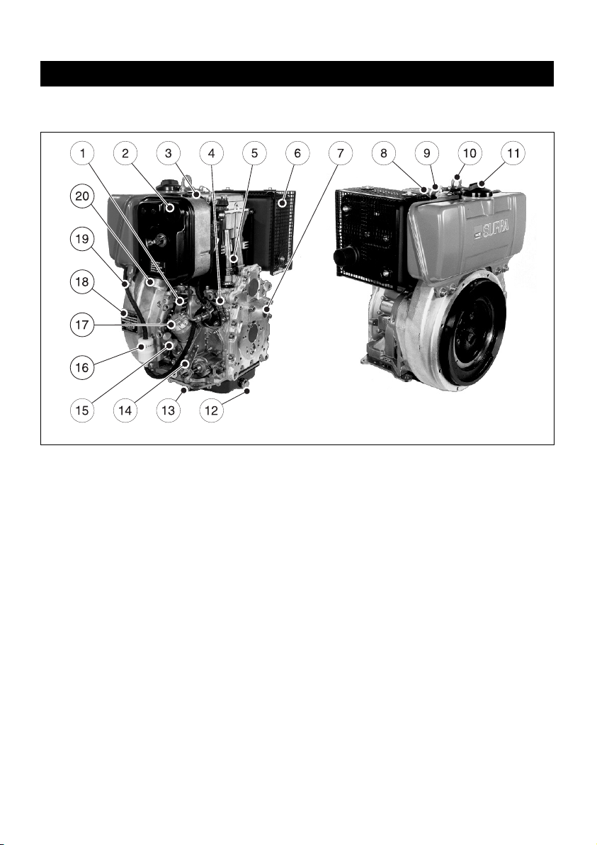
Description of engine
Fully-encapsulated version
1D41C • 1D81C engines
2
1 Capsule
2 Decompression lever
3 Cold-start oil metering device
4 Combustion and cooling air intake
5 Oil filter
6 Cleaning hatch
7 Side panels
8 Hold for starting handle
9 Suspension lug
10 Silencer (muffler), encapsul.
11 Cooling air outlet
12 Battery connection and central plug
for electrical system
13 Stop lever
14 Speed control lever
15 Oil drain plug
16 Oil filler and dipstick
17 Type plate
2392 / 1 2392 / 4
Page 8

7
3. General information
3.1. Technical data
Type 1D41. 1D50. 1D81. 1D90.
Engine models S, Z, C S, Z S, Z, C S, Z
Mode of operation air-cooled four-stroke diesel engine
Combustion method Direct-fuel injection
Number of cylinders 1 1 1 1
Bore / stroke mm 90 / 65 97 / 70 100 / 85 104 / 85
Displacement cm³ 413 517 667 722
Engine oil content without filter approx. L 1.1
1)
1.4
1)
1.8
1)
1.8
1)
with filter approx. L 1.2
1)
1.5
1)
1.9
1)
1.9
1)
Volume of oil between
„max“ and „min“ marks approx. L 0.4
1)
0.5
1)
0.9
1)
0.9
1)
Consumption of lubrication oil
after running-in period approx. 1 % of fuel consumption at full load
Engine oil pressure
Oil termperature 100 ± 20 °C min. 0.6 bar at 850 r.p.m.
Direction of rotation
looking at the flywheel counterclockwise
Valve clearance at 10 - 30 °C
Inlet mm 0.20 0.10 0.10 0.30
Exhaust mm 0.20 0.20 0.20 0.30
Max. angle from vertical in any
direction (continuous operation) max. 30°
2)
30°
2)
30°
2)
30°
2)
Weight (incl. fuel tank, air-cleaner,
exhaust silencer and electric starter)
Engine model S approx. kg 75 76 89 90
Engine model Z approx. kg 77 78 91 92
Engine model C approx. kg 96.5 – 121
Model S: non-encapsulated, normal system of balancing
Z: non-encapsulated, add. system of balancing
C: SILENT PACK, add. system of balancing
1)
These data are approx.-values. The max. mark on oil dipstick counts.
2)
Exceeding these limits causes engine breakdown.
Page 9
3.2. Transport
A lug is provided on top of the engine
as standard equipment, so that the engine and its auxiliaries can be lifted safely. It
is not suitable for lifting complete machines or
similar with the engine attached, and this is
strictly prohibited. (See Chapter 2.)
3.3. Instructions for installation
The „Manual for Selection and Installation of Engines“ contains all the information you need if
your engine has not yet been installed on or in
the equipment it is intended to drive, or set up
in its correct operating position. You can obtain
a copy of this manual from your nearest HATZ
service station.
3
The permitted loads and elements on
the speed adjusting lever and the stop
lever should be observed as an exess can lead
to damage to the contacts and inner governor
parts.
3.4. Load on engine
See supplemental information for EPA certified
engines, Page 35; resp. supplemental information for California regulations for off road
engines, Page 51.
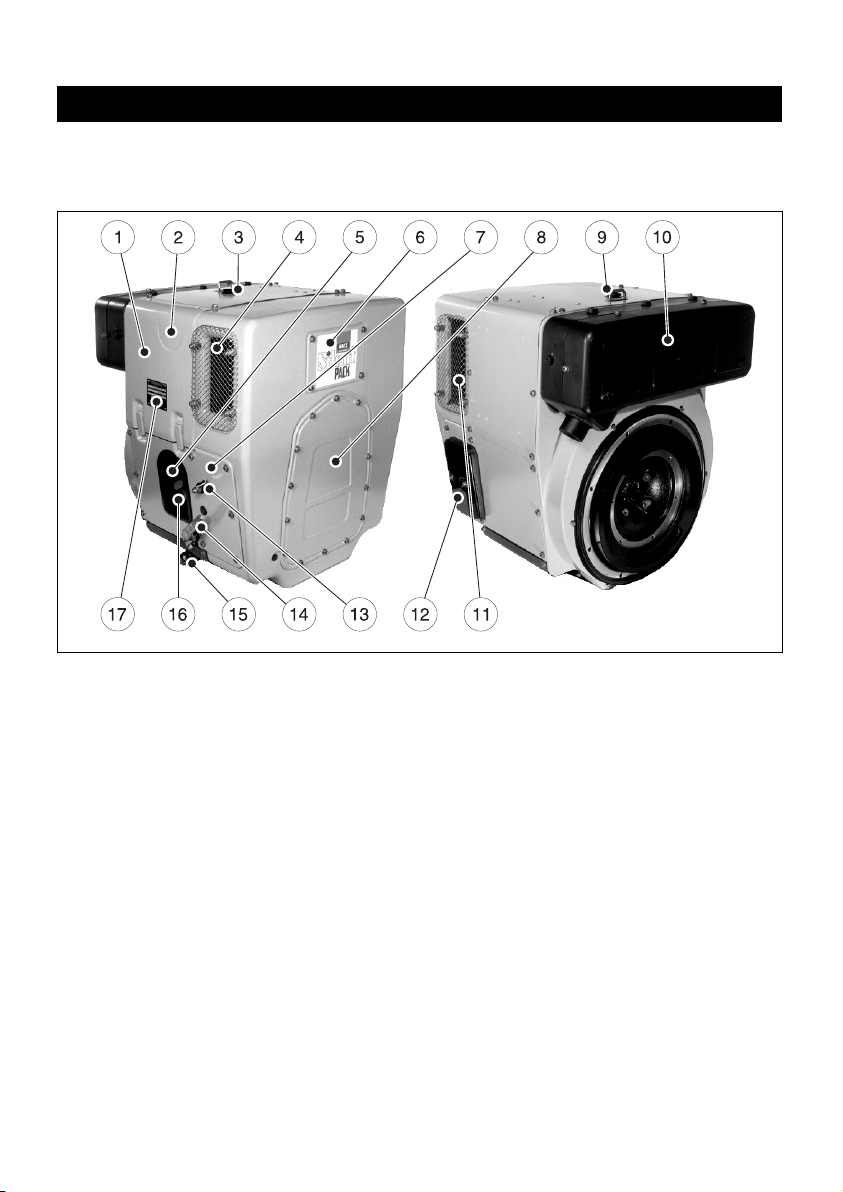
3.5. EPA/CARB-type plates and
fuel label
There are two EPA/CARB- type plates applied for
the identification of the engine. The type plates
are placed on the crankcase resp. on the capsule
(chapt. 2).
They include the following emission control information (Figure 4a):
Label 1/2
4a
➀ EPA/CARB-Engine Family Number
➁ engine type / spec. (only for special
equipment) /Fuel Delivery Timing
➂ engine number
➃ max. engine rated speed
➄ build date
➅ displacement
➆ rated power
➇ “constant speed only” (if requested)
➈ “variable speed” (if requested)
Every engine is equipped with an additional
loose engine type plate. If the original type
plate on the engine is not readily visible after
the engine is installed in the equipment then
the second loose type plate must be attached
on the equipment in such a manner that it is
readily visible to an average person.
The layout is identical for constant-speed and
variable speed application.
70°
F 120 N
M 12.6 Nm
–
–
F 10 N
M 0.35 Nm
–
–
<
<
<
<
START
STOP
+
8
➀
➁
➂
➃
➆
➇
➅
➄
➈
Page 10

For any offer as well as spare parts orders it is
necessary to mention the following data (also
see spare parts list, page 1):
➁ engine type / spec.
(only for special equipment)
➂ engine number
➃ max. engine rated speed
Attention:
If the engine was certified for constant-speed
application and shall be used so, the field "constant-speed only" is marked with “X”.
If the engine was certified for variable speed application and shall be used so, the field "variable
speed" is marked with “X”.
Always install the engine for its intended application in order to comply with EPA and CARB
emission regulation requirements.
Label 2/2
4b
The engine must be operated with “LOW SULFUR FUEL OR ULTRA LOW SULFUR FUEL
ONLY”.
The label also states the applicable emissionrelated power category of the engine.
Fuel label
4c
The fuel label is placed nearby the fuel inlet.
If there was no fuel tank mounted to the engine,
the label has to be permanently attached to the
equipment near the fuel inlet.
3.6. EMISSION-RELATED
INSTALLATION INSTRUCTIONS
See supplemental information for EPA certified
engines, Page 35; resp. supplemental information for California regulations for off road
engines, Page 51.
9
LOW SULFUR FUEL OR ULTRA
LOW SULFUR FUEL ONLY
EMISSION CONTROL INFORMATION
LOW SULFUR FUEL OR
ULTRA LOW SULFUR FUEL ONLY
❏ < 8 kW / ❏ 8-19kW / ❏ 19-37kW /
❏ 37-56 kW PM Standard: 0.3 g/kWh
Power category:
Label 2/2
Page 11
4. Operation
4.1. Before initial start-up
Engines are normally delivered without fuel and
oil.
4.1.1. Engine oil
Qualified are all trademark oils which fulfil at
least one of the following specifications:
ACEA – B2 / E2 or more significant
API – CD / CE / CF / CF-4 / CG-4 or more
significant.
If engine oil of a poorer quality is used, reduce
oil change intervals to 150 hours of operation.
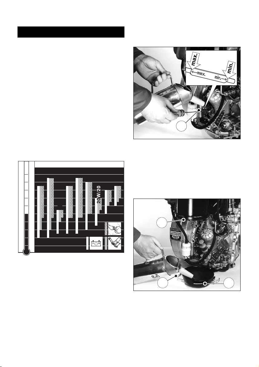
Oil viscosity
5
Choose a viscosity according to the ambient
temperatures where the engine is to be started
from cold.
The engine must be in a horizontal position before adding oil or checking the oil level.
6
– Pull out dipstick „1“ and add engine oil of the
correct specification and viscosity up to the
„max“ mark on the dipstick; (Chapter 3.1.).
4.1.2. Oilbath air cleaner
7
– Take off the oil reservoir and fill it up to the
mark „1“ using engine oil.
– Attach the oil reservoir, making sure that seal-
ing ring „2“ is correctly seated and catches „3“
are tight.
2393 / 6
2
3
1
1
-40
-30
-20
-10
0
10
20
30
40
50
104
86
68
50
32
14
-4
-22
-40
OIL: SAE...
°C°F
5W/30
5W/40
10W/40
10W/30
15W/40
30
40
122
10 W
10
Page 12
4.1.3. Fuel
Only refuel when engine is stopped.
Never refuel close to open flames or
flammable sparks, don’t smoke. Use only pure
fuel and clean replenishing cups. Don’t spill
the fuel.
All diesel fuels sold as fuel and complying with
the following minimum specification can be
used:
EN 590 or
BS 2869 A1 / A2 or
ASTM D 975 - 1D / 2D
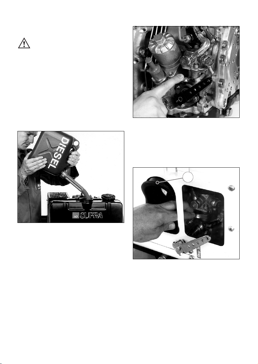
8
– Before the first start or if the fuel tank has
been run dry, completely fill the fuel tank with
diesel.
The fuel system is bled automatically if the
fuel tank is attached to the engine or located
higher than the injection pump.
9
– If the fuel tank is not mounted on top of the
engine, or is at a lower level, operate the lever
on the fuel feed pump until fuel is heard to
flow back to the tank through the return line.
10
– On fully encapsulated engines, move sleeve
„1“ to one side to gain access to the feed
pump.
After operating the feed pump, make sure that
the sleeve is replaced correctly and makes a
good seal.
1
2292 / 4
2287 / 11
2286 / 2
11
Page 13
At temperatures below 0 °C, winter-grade fuel
should be used or parafin added to the fuel well
in advance.
4.1.4. Mechanical oil pressure
monitor
(optional extra)
The mechanical oil pressure monitor should be
activated:
• when first filling, or after running the fuel tank
dry.
• if engine shut down automatically because lu-
bricating oil supply was inadequate.
• after freeing it by turning at low temperatures
(Chapter 4.2.4.)
• after replacing the fuel filter, Chapter 5.4.1.
– Add fuel, chap. 4.1.3.
– Check engine oil level, chap. 5.2.1.
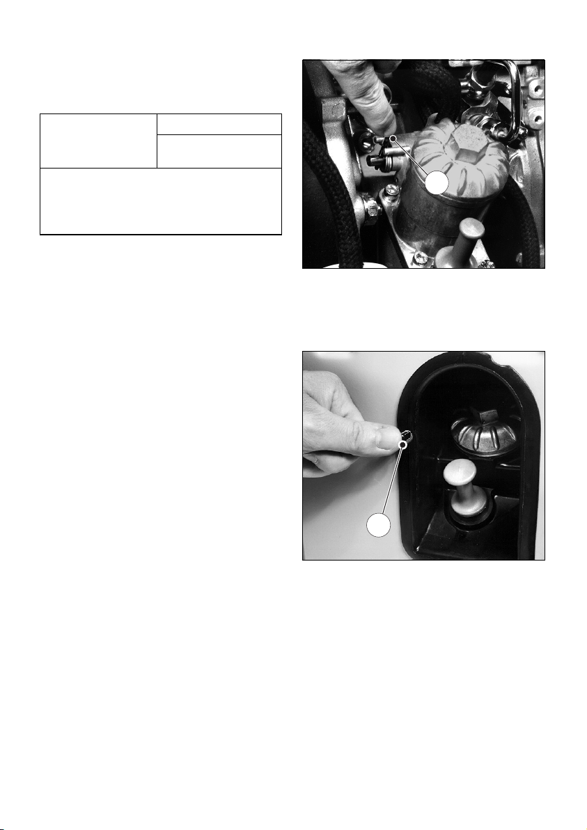
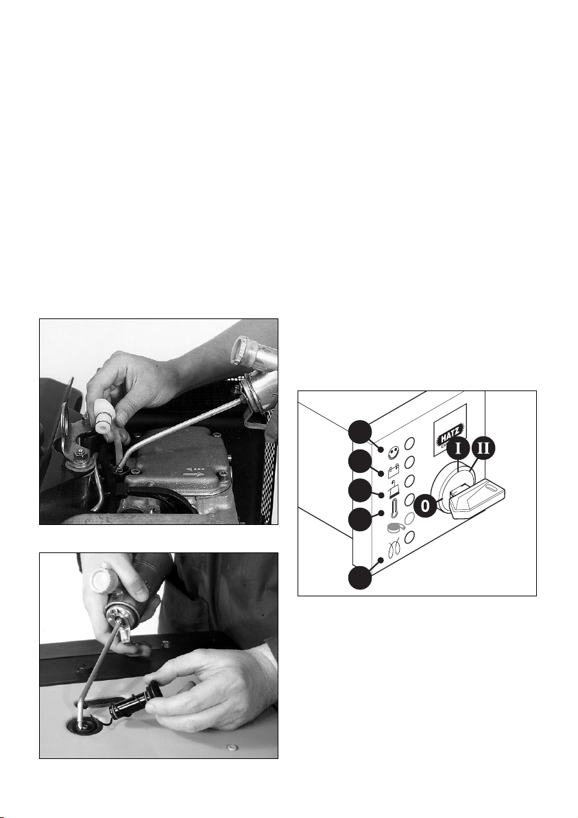
11
– To activate the monitor, press lever „1“ for
approx. 15 seconds.
12
– If the engine has a full capsule, press pin „1“
for app. 15 seconds.
– If the engine has a fuel feed pump, operate its
lever for several strokes at the same time
(Figs. 9 and 10).
– Re-assemble all parts repositioned or re-
moved. Check that capsule elements make a
good seal.
2392 / 12
1
1
Lowest ambient
temperature when
starting, in °C
Paraffin content for:
Summer Winter
fuel fuel
0 up to –10 20 % –
–10 up to –15 30 % –
–15 up to –20 50 % 20 %
–20 up to –30 – 50 %
12
Page 14

13
Instructions to activate the mechanical oil pressure control are mentioned on the sticker placed
on the engine.
IMPORTANT !
Even with mechanical oil pressure monitoring
the oil level must be checked every 8 – 15
operating hours (Chapter 5.2.1.).
4.2. Starting the engine
Do not run the engine in closed or
badly ventilated rooms – danger of
poisoning ! Before the engine is started, always make sure that nobody is in the danger
area (moving parts on engine or machinery)
and that all safety guards are in place.
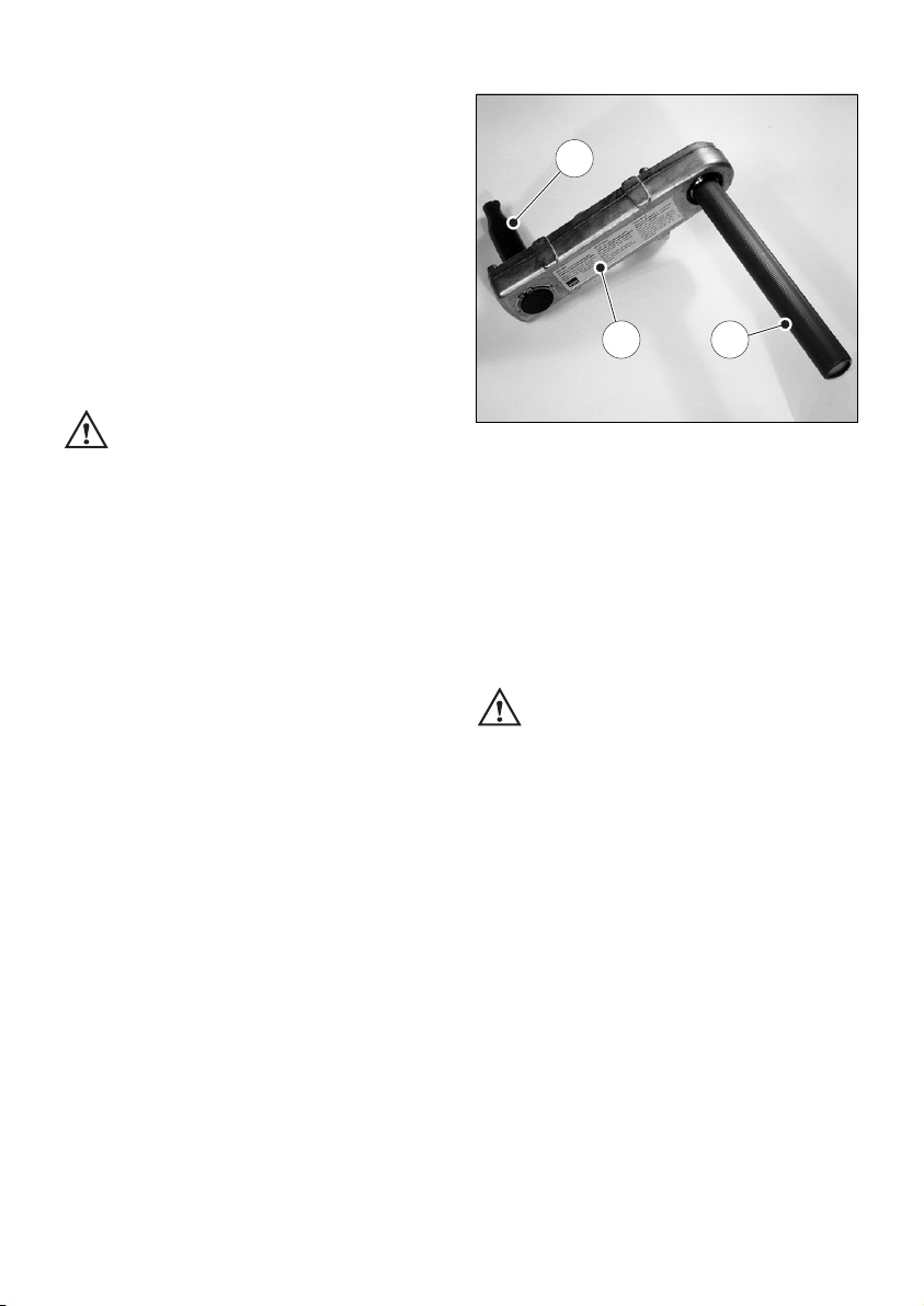
Check that the starting handle is in good condition: renew tubular grip if broken, worn drive pin
etc.
Lightly grease the sliding-contact area between
the starting handle and the guide sleeve.
14
Never use any spray starting aids.
4.2.1. Preparations for starting
– If possible, disengage the engine from any
driven equipment. The auxiliary equipment
should always be placed in neutral.
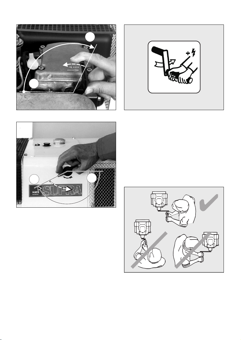
15
– Set speed control lever „1“ to a position be-
tween 1/2 START and max. START, according
to requirements. Selecting a lower engine
speed will reduce smoke when starting.
– Make sure that stop lever „2“ - if fitted - is in
the operating „START“ position.
2396 / 3
2
1
START
START
STOP
STOP
050 145 00
L3 / 250
13
Page 15
16
17
– Turn the decompression lever until stop „1“ is
reached. In this position the automatic decompression system is heard to engage and the
engine can then be started; Figs. 16 and 17.
18
After the automatic decompression device has
engaged at its limit stop, five turns of the crank
handle are needed for the engine to build up
compression and fire again.
4.2.2. Starting with the handle
For preparations to start the engine,
see Chapter 4.2.1.
19
For correct position to adopt when starting the
engine, see Fig. 19.
5x
050 252 00.874
1
0
2292 / 6
1
0
2283 / 4
14
Page 16
– Take hold of the starting handle with both
hands and turn it at increasing speed. The
maximum speed of rotation must have been
reached by the time the decompression lever
has returned to the „0“ position (compression). As soon as the engine has started, pull
the starting handle out of the guide sleeve.
– If the engine backfires because the crank han-
dle was not turned firmly enough (the engine
may even start to run backwards), release the
crank handle immediately and stop the engine
(Chapter 4.3.).
There is a risk of injury from the
rotating crank handle.
– To restart the engine, wait until it has come to
a standstill, then repeat the starting preparations.
Safety precaution
For greater protection against accidental injury
when starting with the handle, a handle with
kick-back damping can be used.
4.2.3. Starting with the handle with
kick-back damping (retrofit)
For preparations to start the engine,
see Chapter 4.2.1.
– For correct position to adopt when starting the
engine, see Fig. 19.
20
– Always hold tubular grip „1“ with both hands.
– Turn the handle slowly until the pawl engages
in the ratchet, then increase turning force to
build up speed. The highest speed must have
been reached when the decompression lever
returns to the „0“ position (compression). As
soon as the engine has started, pull the starting handle out of the guide sleeve.
You must hold the tubular grip firmly to
maintain contact all the time between
the starting handle and the engine. Maintain
turning force during the entire hand starting
operation.
If backfiring occurs when starting the engine because the crank handle was not turned firmly
enough, the brief reverse rotation at the handle
tube separates the link between crank lug „2“
and driving dog „3“ (Fig. 20).
– If the engine begins to run backwards after
backfiring (smoke emerges from air cleaner),
release the crank handle immediately and stop
the engine (Chapter 4.3.).
– To restart the engine, wait until it has come to
a standstill, then repeat the starting preparations.
3
2 1
2395 / 4
15
Page 17
4.2.4. Starting in cold weather
At temperatures below app. –5 °C, always turn
the engine over to ensure that it rotates freely.
– Move the speed control lever to the START
position; Fig. 15.
– Move the decompression lever to a position
not as far round as starting position „1“
(Figures 16 and 17).
– Turn the engine over with the starting handle
until it is felt to rotate more freely (10 – 20
turns of the starting handle).
– If mechanical oil pressure monitoring is
fitted, press lever „1“ or pin „1“ in for about
15 seconds (Figs. 11 and 12).
21
22
– Remove dirt from the cover of the metering
device and the surrounding area. Pull off the
cover; Figs. 21 and 22.
– Add a free-flowing lubricating oil to the
housing until the level reaches the upper rim.
Replace the cover and press it in firmly. Two
filling operations in succession are needed.
– Turn the decompression lever until
limit stop „1“ (fig. 16 and 17).
– After this, start the engine immediately.
Chap. 4.2.1. / 4.2.2. / 4.2.3.
4.2.5. Electric starter
For preparations to start, see Chapter 4.2.1.
– The decompression lever remains in pos. „0“.
Starting procedure
23
– Insert the key to its stop and turn it to
position I.
– Battery charge telltale „2“ and oil pressure
warning „3“ must light up.
1
2
3
4
5
2392 / 9
2283 / 8
16
Page 18

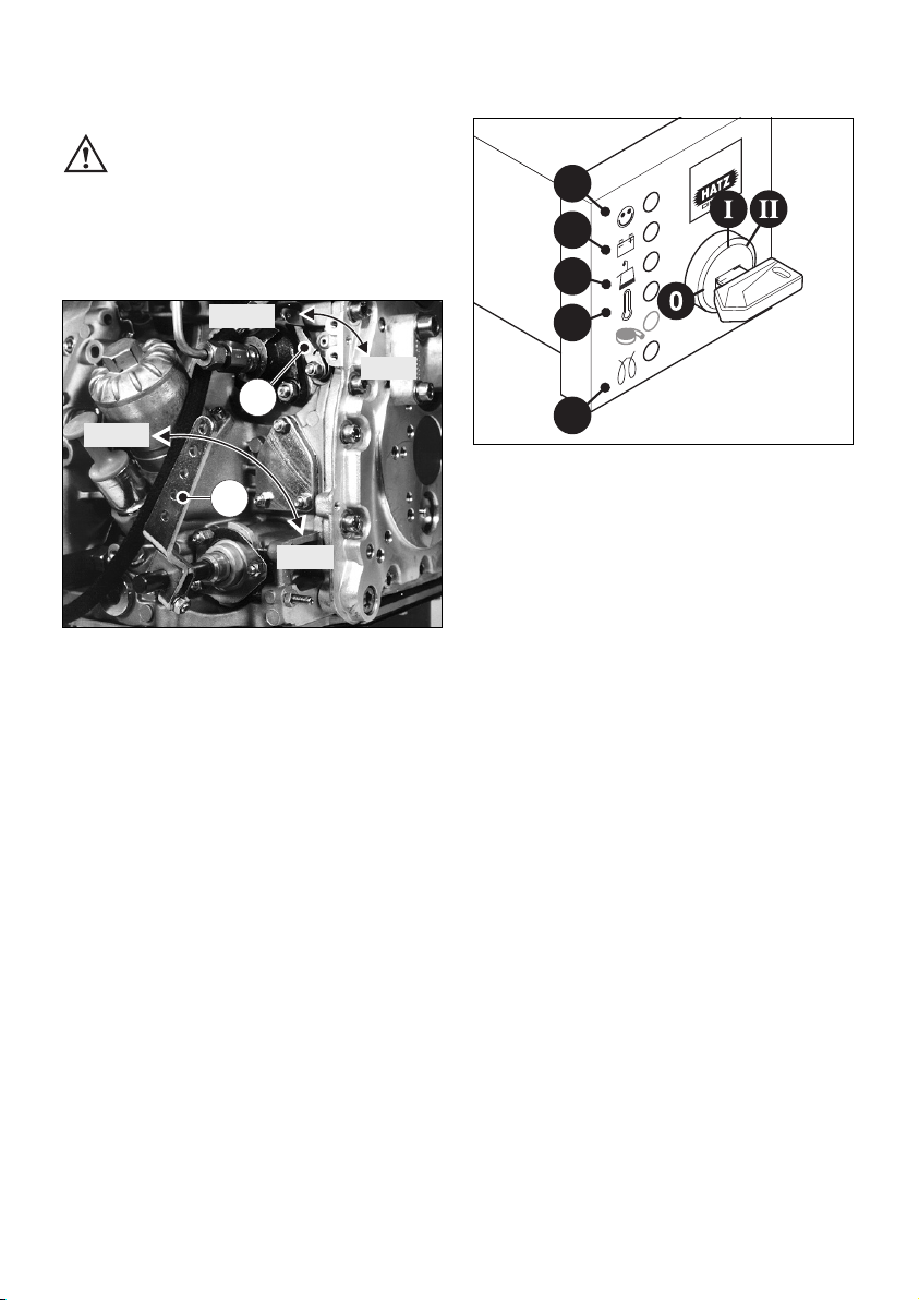
– Turn start key to position II (fig. 23).
– As soon as the engine runs, release the start
key. It must return to position I by itself and
remain in this position during operation.
The battery charge telltale and oil pressure
warning must go out immediately after starting. Indicator light „1“ is on when the engine
is in operation.
– If anything seems to be incorrect, stop the en-
gine immediately and trace and rectify the fault
(chapt. 6).
– The engine temperature display „4“ (additional
equipment) lights up if the temperature at the
cylinder head becomes too high.
Switch off the engine and trace and eliminate the cause of the problem, chap. 6.
– Always turn the start key back to position 0
before re-starting the engine. The repeat lock
in the ignition lock prevents the starter motor
from engaging and possibly being damaged
while the engine is still running.
Never operate the electric starter when
the engine is running or coasting to a
standstill. There is a risk of broken starter pinion or ring gear teeth.
Important:
If a start protection module is installed, the start
key has to be returned to position 0 for at least
8 seconds if the engine has failed to start before
a further attempt to start the engine can be
made.
Preheating device with automatic
heating timer
(additional equipment)
The preheating light „5“ lights up additionally at
temperatures below 0° Celsius (Fig. 23).
– After the light has gone out, start the engine
without delay.
Automatic electrical shutdown system
(additional equipment)
This is characterized by a brief flashing of all
pilot lamps once the starter key has been turned
to position I (Fig. 23).
Important !
If the engine cuts out immediately after starting
or switches off by itself during operation, a
monitoring element in the automatic shutdown
system has tripped. The corresponding indicator
light (Fig. 23, positions 2 - 4) will come on.
After the engine has stopped, the display continues to glow for about 12 seconds.
The electrical device then switches itself off automatically.
The display lights up again after the start key
has been turned back to position 0 and then to
position I again.
Trace and eliminate the cause of the operating
fault before trying to restart the engine
(see chapter 6).
The display light goes out when the engine is
next started.
Even with automatic shutdown monitoring the
oil level must be checked every 8 – 15 operating hours (Chapter 5.2.1.).
17
Page 19
4.3. Stopping the engine
Never stop the engine by moving the
decompression lever. During breaks
in work or at the conclusion of the working period, keep the starting handle and starting key
in a safe place, out of reach of unauthorized
persons.
24
– Move speed control lever „1“ back to the
STOP position.
– On engines with the lower engine speeds
not accessible, move speed control lever „1“
back, then move stop lever „2“ in the STOP
direction. Hold it there until the engine has
stopped.
– Release the stop lever „2“ when the engine
has stopped, making sure that the lever returns to its normal operating position.
Electrical system
25
The charge „2“ and oil pressure telltales „3“
come on.
– Turn the key to the 0 position and pull it out.
The telltale lights must then go out.
Note:
Engines with an automatic electrical shutdown
system (Chapter. 4.2.5.) can also be switched
off by turning the start key back to position 0.
1
2
3
4
5
2396 / 3
2
1
START
START
STOP
STOP
18
Page 20
19
5. Maintenance
The engine must be stopped before any maintenance work is attempted.
Comply with legal requirements when handling and disposing of old oil, filters and
cleaning materials.
Keep the engine’s starting key and starting handle out of reach of unauthorized persons.
To immobilize engines with an electric starter, disconnect the negative battery terminal.
At the end of the maintenance work, check that all tools have been removed from the engine and
all safety guards, covers etc. replaced in their correct positions.
Before starting the engine, make sure that nobody is in the danger area (engine or driven
machinery).
5.1. Maintenance summary
Maintenace intervals Maintenance work required Chap.
Every 8 – 15 operating
hours or before daily
starting.
Check oil level.
Check area round combustion air input.
Check the air cleaner maintenance indicator.
Check the cooling air zone.
Check the water trap.
Check the lower part of the oilbath air cleaner for
correct oil level and freedom from dirt; renew oil if
sludge has formed.
5.2.1.
5.2.2.
5.2.3.
5.2.4.
5.2.5.
4.1.2.
5.3.1.
Every 250 operating
hours
Maintenance of oil bath air filter.
Replace engine oil and oil filter.
Check and adjust tappet clearance.
Clean cooling air system.
Examine screw connections.
Cleaning mesh insert in exhaust silencer
5.3.1.
5.3.2.
5.3.3.
5.3.4.
5.3.5.
5.3.6.
Every 500 operatinghours
Replace fuel filter.
Maintenance of dry-air filter.
5.4.1.
5.4.2
8-15
500
250
Page 21
26
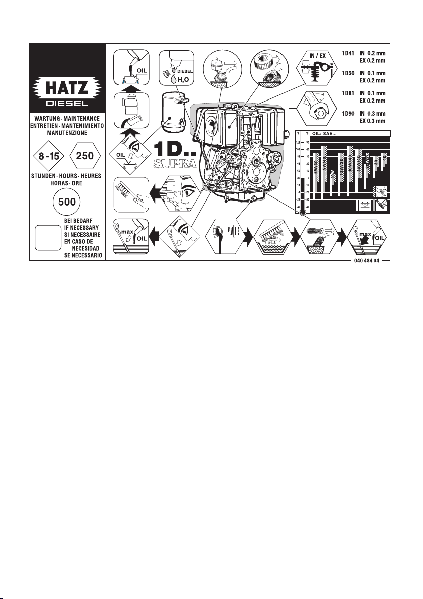
The above maintenance chart is supplied with
every engine. This label should be affixed to the
engine or equipment in an easily visible position.
The maintenance chart governs the maintenance
intervals.
For new or reconditioned engines, the following
must always be carried out after first 25 operat-
ing hours:
– Replace engine oil and oil filter, chap. 5.3.2.
– Check tappet clearance, and adjust if neces-
sary, chap. 5.3.3.
– Examine screw connections, chap. 5.3.5.
Do not tighten the cylinder head fastening.
For short operating periods: replace engine oil
and oil filter after 12 months at the latest, regardless of the number of operating hours.
20
Page 22

21
5.2. Maintenance every 8 – 15
hours of operation
5.2.1. Check engine oil level
When checking the oil level, the engine should
be standing level, and must not be running.
– Remove any dirt in the dipstick area.
27
– Check oil level at the dipstick; top up if neces-
sary as far as the „max“ mark
(see Chapter 4.1.1.).
5.2.2. Check air intake point
Severe contamination is a sign that there are
large amounts of dust in the atmosphere and
the air cleaner maintenance intervals should be
reduced.
– Depending on the air intake pattern, check for
severe blockage; clean if necessary
(see Chapter 2).
28
– Check that dust outlet „1“ on the centrifugal
dust trap (depending on version) is not
blocked, and clean if necessary.
5.2.3. Air cleaner blockage indicator
(optional extra)
– Run the engine at full speed shortly.
29
If the rubber bellows is pulled in and obscures
the green zone „1“, maintenance work is due on
the air cleaner; Chapt. 5.4.2. In dusty operating
conditions, check the rubber bellows several
times a day.
2391 / 10
1
2393 / 10
1
Page 23

5.2.4. Checking cooling air zone
Severe contamination is a sign that there are
large amounts of dust in the atmosphere and
that maintenance intervals should be reduced.
– Check the air inlet and outlet zones for block-
age by coarse material such as leaves, large
amounts of dust etc., and clean if necessary
(see chapters 2 and 5.3.4.).
– If a temperature warning light „4“ is provided,
it will come on if the engine overheats, fig. 25.
In this case, stop the engine immediately
(Chapter 4.3. and 5.3.4.).
5.2.5. Checking the water trap
The intervals at which you should check the
water trap depend entirely on the amount of
water in the fuel and the care taken when refuelling. The normal interval is once a week.
30
– Loosen hexagon screw „1“ with approx. 2-3
rotations.
– Trap the drops which emerge in a transparent
vessel. Since water has a greater specific
gravity than diesel fuel, the water emerges before the diesel fuel. The two substances separate at a clearly visible line.
– As soon as diesel only emerges at screw „1“,
this can be tightened again.
If an external water trap is attached, check its
water content every day, when the engine oil
level is checked. The water which has collected
is separated at a clearly visible line from the
diesel fuel above it.
31
– Open drain plug „1“ and drain the water out
into a suitable vessel.
– If the drain plug is difficult to reach, an exten-
sion hose can be attached to it.
2396 / 9
1
2396 / 7
1
22
Page 24

5.3. Maintenance every 250
hours of operation
5.3.1. Oilbath air cleaner maintenance
32
Catch waste oil and dispase acc. to
environmental regulations.
– Take off the oil reservoir „1“ and clean it.
– Remove contaminated oil and sludge from the
oil tank, and clean it out.
– Take off rain cap „2“ and clean it.
– Clean the entire length of intake pipe „3“.
– Check the inserted seal and renew if in poor
condition.
– Fill the oil reservoir up to the mark with engine
oil and re-assemble the oilbath air cleaner,
Chap. 4.1.2.
– If the filter pack is very dirty, also clean the
upper part of the air cleaner as follows:
Remove the upper part of the air cleaner from
the engine and rinse it in diesel oil.
– Before re-assembling the air cleaner, allow the
diesel fuel to drip off thoroughly, or wipe it off.
– Never attempt any repairs (welding, brazing
etc.) to the oilbath air cleaner, or it may be
rendered useless and the engine may also be
damaged.
– If the sealing face is uneven, the air cleaner
body cracked and/or the filter wool content is
incomplete, install a new air cleaner.
– Attach the upper part of the air cleaner with a
new flange gasket.
33
– Sealing package acc. picture 33 is mounted at
engines 1D41 and 1D50.
34
– Shim washers „1“ should be installed with the
convex side (outward curve) towards the nut.
– Re-assemble the complete air cleaner and fill it
with oil to make it ready for further operation.
1
2395 / 13
23
Page 25

5.3.2. Changing engine oil,
renewing oil filter
The engine must be stopped, and should stand
on a flat, level surface.
Drain the engine oil only when it is warm.
For oil drain plug, see Chapter 2.
Risk of scalding from hot oil.
Catch waste oil and dispase acc. to
environmental regulations.
– Unscrew the oil drain plug and allow all the oil
to drain out.
Fully encapsulated engines:
35
When unscrewing oil drain plug „1“, make sure
that the drain tube is not loosened. Prevent it
from turning if necessary with an open-ended
wrench of the correct size.
– Clean the oil drain plug and attach a new seal.
Insert and tighten the plug.
36
– Renew the replaceable lubricating oil filter ele-
ment.
37
– Clean sieve bottom carefully in order not to
bend the netting.
Wipe out cap screw or blow it out with compressed air.
Persons handling compressed air must
wear protective goggles.
Important !
Note the „TOP“ mark on the oil filter. Fig. 36
1
2287 / 13
2292 / 9
1
24
Page 26

– Check condition of O-ring „1“ and renew it if
necessary (Fig. 36).
– Wet the thread and the O-ring of the screw
plug with lubricant „K“ (see spare parts list).
– Add engine oil up to the „MAX“ mark on the
dipstick (see Chapter 4.1.1.)
– Run the engine for a short period, then check
the oil level again and top up if necessary.
– Check that there is no leakage past screw plug
on the oil filter housing.
5.3.3. Checking and adjusting
valve clearances
– Move the decompression lever to
position „0“; Fig. 16 and 17.
1D41 C, 1D81 C and 1D90 C engines
Take off the enclosure cover (see Chap. 2).
On engines with manual starting only, the decompression lever is also taken off when the
cover is removed.
38
– Unscrew cover „1“ and take off together with
gasket „2“. Never re-use this gasket.
– Turn the engine over in the normal direction of
rotation until compression is felt.
39
– Check valve clearances between rocker and
valve stem, using feeler gauge „1“; Fig. 39
(see Chapter 3.1.).
– If valve clearance is incorrect, slacken off hex.
nut „2“.
– Turn adjusting screw „3“ with a screwdriver
until feeler gauge „1” can just be pulled
through between the rocker and the valve
stem with slight resistance to its movement
after nut „2“ has been retightened.
– Attach the cover at the cylinder head again and
tighten down uniformly.
– Depending on version mount parts of air duct.
– Run the engine briefly and check that the
cover is not leaking.
1 2
3
2287 / 4
2393 / 15
0
1
2
25
Page 27

5.3.4. Clean the cooling air system
Before cleaning, the engine must be
stopped and allowed to cool down.
Remove parts of air duct.
Dry contamination
– Clean all air guide elements and the complete
cooling air zones on the cylinder head, cylinder and flywheel blades without making them
wet. Blow them dry with compressed air.
Persons handling compressed air must
wear protective goggles.
Moist or oily contamination
– Disconnect the battery. Clean the complete
area with a solvent, cold cleaner etc. according
to its manufacturer’s instructions, then spray
down with a powerful water jet.
Do not splash electrical device with water jet
or pressure jet during engine cleaning.
– Trace the cause of any contamination with oil
and have the leak eliminated by a HATZ
service station.
– Install the air guide elements previously re-
moved.
The engine must never be run without
the air guide elements in position.
– Immediately after re-assembly, run the engine
until warm to prevent residual moisture from
causing rust.
5.3.5. Checking threaded connections
Check the condition and tightness of all threaded
connections, wiring, hose clips and other components attached to the engine and its mountings, provided that these can be reached during
maintenance work.
Do not tighten the cylinder head bolts.
40
Adjustment screws on speed governor
and injection system are painted with
safty lacquer. Do not tighten or adjust them.
5.3.6. Cleaning mesh insert in exhaust
silencer
(additional equipment)
41
– Remove deposits from the mesh insert with a
suitable wire brush.
2396 / 3
26
Page 28

5.4. Maintenance every 500
hours of operation
5.4.1. Renewing fuel filter
Fuel filter maintenance intervals depend on the
purity of the fuel used; reduce them to 250
hours of operation if necessary.
Do not smoke or bring a naked flame
near the fuel system when working
on it.
Important !
Keep the entire area clean so that no dirt
reaches the fuel. Fuel particles may damage
the injection system.
42
– Shut off the fuel supply line upstream and
downstream of the fuel filter according to
item 1.
43
– Unscrew the fuel filter from its mount.
44
– Place a suitable vessel under the filter to trap
escaping fuel.
– Pull off fuel supply line „1“ at both ends of fuel
filter „2“ and insert the new filter.
– Always renew the fuel filter. Note the arrows
indicating the correct direction of fuel flow.
– Secure the filter to its mount.
– Open the fuel supply line or prime the pump
until the fuel flows (see Chapter 4.1.3.).
1
2
1
27
Page 29

– Activate mechanical oil pressure monitor
(optional extra), chap. 4.1.4.
– Run the engine briefly to check the fuel filter
and lines for leaks.
5.4.2. Dry-type air cleaner maintenance
It is best to clean the filter cartridge only when
the maintenance indicator displays the appropriate signal.
Apart from this, the cartridge should be renewed
after 500 hours of operation.
– On fully encapsulated engines, take off the top
cover (see Chapter 2).
On engines with manual starting only, the decompression lever is also taken off when the
cover is removed.
45
– Slacken off wing bolt „1“ and remove it with
cover „2“.
46
– Carefully pull out filter cartridge „1“.
– On the version with air cleaner maintenance
indicator, check that valve plate „4“ is clean
and in good condition.
Noise reduced model
47
– Unscrew hex. nut „1“ and take off filter hous-
ing „2“.
2392 / 15
1 2
2393 / 1
42
1
2396 / 16
1
2
28
Page 30

48
– Unscrew the hex. nuts and remove them with
filter cover „1“.
– Carefully pull out filter cartridge.
– Clean all parts except for the filtercartridge.
Do not spray into the engine’s air intake when
cleaning.
Cleaning the filter cartridge
Dry contamination
49
– Blow through the filter cartridge from the in-
side, moving the jet of dry compressed air up
and down until no further dust is expelled.
Warning: air pressure must not exceed 5 bar.
Persons handling compressed air must
wear protective goggles.
– Tilt the filter element and hold it against the
light (or shine a light through it) to trace any
cracks or other damage.
Important:
If there is even the slightest damage to paper
filter element „2“ or sealing lips „3“, the filter
element should not be re-used.
(Figs. 46 and 48)
Wet or oily contamination
– Renew the filter cartridge.
– Re-assemble in the reverse order of work.
2281 / 5
2392 / 16
2
1
3
29
Page 31

30
6. Malfunctions – Causes – Remedies
Malfunction Possible causes Remedial action Chap.
Engine will not
start or start is
delayed, although
it can be turned
over with the
starter.
Also applicable for
engines with mechanical oil pressure monitoring.
At low temperatures.
Speed control lever is in stop or
idle position.
Stop lever in stop position.
No fuel reaching injection pump.
Compression too low:
- Valve clearances incorrect
- Cylinder bore and/or piston
ring wear
Injector not operating correctly.
Oil pressure lost.
Lower starting temperature limit
exceeded.
Machinery not uncoupled.
Defective preheat system
(optional extra).
Set lever to „START“-position
Add. fuel.
Check entire fuel supply system
carefully.
If no fault is found:
- supply line to engine
- fuel filter
- Function of delivery pump
must be checked.
Check valve clearances, adjust if
necessary.
See workshop manual.
See workshop manual.
Check engine oil level.
Activate mechanical oil pressure
monitor.
Comply with cold starting
instructions.
Operate preheat system
(optional extra).
Disengage engine from machinery or equipment if possible.
See workshop manual.
4.2.
4.1.3.
4.1.4.
5.4.1.
4.1.3.
5.3.3.
5.2.1.
4.1.4
4.2.4.
4.2.5.
Page 32

31
Malfunction Possible causes Remedial action Chap.
At low
temperatures.
Starter does not
run or engine is
not turned over.
Engine fires but
stops again as
soon as starter is
switched off.
Fuel separates has inadequate
resistance to low temperatures.
Starting speed too low:
- Engine oil is too thick
- Battery charge is insufficient.
Fault in electrical system:
- Battery and/or other wiring is
wrongly connected.
- Wiring connections loose
and/or corroded.
- Battery defective and/or flat.
- Defective starter motor
- Defective relays, monitoring
elements etc.
Drive still engaged.
Fuel filter blocked.
Fuel supply interrupted.
Stop signal from monitoring
element for automatic shutdown
system (optional extra):
- oil pressure lost
- cylinder head temperature
too high.
- alternator has failed
Check whether clear (not turbid)
fuel emerges at the fuel line detached from the injection pump.
If turbid or separated - either
warm up the engine or drain the
complete fuel supply system.
Refuel with winter-grade fuel to
which paraffin has been added.
Refill with a different grade of
engine oil.
Check the battery; consult a specialist workshop if necessary.
Check electrical system incl.
indiv. components or contact a
HATZ-service station.
Uncouple engine from driven
machinery if possible.
Renew the fuel filter.
Check through the entire fuel
supply systematically.
Check oil level.
Clean cooling air system.
See workshop manual.
4.1.3.
5.3.2.
7.
7.
5.4.1.
5.2.1.
5.3.4.
Page 33

32
Malfunction Possible causes Remedial action Chap.
Engine stops by
itself during regular operation.
In addition, if automatic engine shutdown is installed.
Low engine power,
output and speed.
Fuel supply is interrupted:
- Tank run dry
- Fuel filter blocked
- Defective feed pump.
- Air in the fuel system.
Mechanical oil pressure monitor
stops the engine due to low oil
pressure.
Mechanical defects.
Stop signal from monitoring
element because of:
- oil pressure too low.
- cylinder head temperature
too high.
- alternator has failed
Fuel supply is obstructed:
- Tank run dry.
- Fuel filter blocked.
- Tank venting is inadequate
- Leaks at pipe unions.
- Air in the fuel system.
- Speed control lever does not
remain in selected position.
Add fuel.
Renew fuel filter.
Check through entire fuel supply
system.
Check fuel system for
penetration of air.
Check air vent valve.
Check engine oil level.
Activate mechanical oil pressure
monitor.
Contact a HATZ-service station.
Check engine for:
Engine oil level.
Cooling air passages blocked
or cooling system otherwise
affected.
See workshop manual.
Add fuel.
Renew fuel filter.
Ensure that tank is adequately
vented.
Check threaded pipe unions for
leaks.
Check fuel system for
penetration of air.
Check air vent valve.
Prevent speed control from
moving.
4.1.3.
4.1.4.
5.4.1.
5.2.1.
4.1.4.
4.1.3.
4.1.4.
5.4.1.
Page 34

33
Malfunction Possible causes Remedial action Chap.
Low engine power,
output and speed,
black exhaust
smoke.
Engine runs very
hot. Cylinder head
overheat, telltale
lamp (optional
extra) comes on.
Air cleaner blocked.
Incorrect valve clearances.
Malfunction at injector.
Too much oil in engine.
Inadequate cooling:
- Entire cooling air system
contaminated.
- Inadequate sealing at air guide
plates or capsule elements.
Remove dirt from air cleaner.
Adjust valve clearances.
See workshop manual.
Drain off engine oil down to
upper mark on dipstick.
Clean cooling air system.
Check that air guide plates and
enclosure elements are all present and make a tight seal.
5.3.1.
5.4.2.
5.3.3.
5.3.2.
5.3.4.
Page 35

7. Work on the electrical system
Batteries generate explosive gases.
Keep them away from naked flame
and sparks which could cause them to ignite.
Do not smoke. Protect the eyes, skin and
clothing against battery acid. Pour clear water
over acid splashes immediately. In case of
emergency call doctor.
Do not place any tools on top of the battery.
Always disconnect the negative (–) pole of the
battery before working on the electric device.
– The positive (+) and negative (–) battery ter-
minals must not be accidentally interchanged.
– When installing the battery, connect the posi-
tive lead first, followed by the negative lead.
Negative pole to earth (ground) on engine
block.
– When removing the battery, disconnect the
negative lead first, followed by the positive
lead.
– In all circumstances, avoid short circuits and
shorts to earth (ground) at live cables.
– If electrical faults occur, first check for good
contact at the cable connections.
– Replace a failed indicator light without delay.
– Do not take the key out while the engine is
running.
– Never disconnect the battery while the engine
is running. Electric voltage peaks can cause
damage to electrical components.
– In case of an emergency start in manual
mode, leave the battery (which might be discharged) connected to the engine.
– For emergency operation without battery,
make sure that the plug-and-socket connector
to the instrument box is disconnected additionally before the engine is started.
– Do not splash electrical device with water jet
or pressure jet during engine cleaning.
– When carrying out welding work on the en-
gine or attached equipment, attach the earth
(ground) clip as near as possible to the welding point, and disconnect the battery.
If an alternator is fitted, separate the plug connector leading to the voltage regulator.
The relevant circuit diagrams are supplied with
engines which have an electrical system.
Additional copies of circuit diagrams can be
obtained on request.
HATZ assumes no liability for electrical systems
which was not carried out acc. HATZ circuit diagrams.
8. Protective treatment
A new engine can normally be stored for up to
12 months in a dry place.
If atmospheric humidity is high (or if exposed
to sea air), protection is sufficient for about
6 months’ storage.
If the engine is to be stored for a longer period,
or laid up out of use, please consult the nearest
HATZ service point.
34
Page 36

SUPPLEMENTAL INFORMATION
TO THE OWNER'S MANUAL FOR 2008 AND LATER
EPA CERTIFIED
NONROAD COMPRESSION IGNITION ENGINES.
EPA EMISSION CONTROL SUPPLEMENTAL
WARRANTY STATEMENT AND
EMISSION-RELATED INSTALLATION
INSTRUCTIONS.
35
Page 37

MAINTENANCE AND WARRANTY.
SUPPLEMENTAL INFORMATION TO THE OWNERS MANUAL FOR 2008 AND
LATER EPA CERTIFIED NONROAD COMPRESSION IGNITION ENGINES.
The following supplemental information is furnished for EPA Nonroad Compression
Ignition Engines which are certified according to 40 CFR Part 89 and Part 1039.
This information contains the following specific items:
• EPA-related engine parts and engine operating conditions
• Maintenance instructions for EPA-related engine parts
• Emission control system and adjustments
• Warranty statement
• Emission-related installation instructions
ENGINE PARTS AND / OR EQUIPMENT RELATED TO EPA EXHAUST
EMISSION REGULATIONS.
Parts which are mandatory for engine operation.
The following parts as manufactured according to HATZ specifications are mandatory for
engine operation which meets EPA exhaust emission regulations.
• Fuel injection pump
• Injection nozzle
• Extra fuel device
• Crankcase breather valve assembly
• Air cleaner housing
36
Page 38

• Intake manifold
• Exhaust manifold
• Oil filler cap
• Intake and exhaust gaskets at head interfaces
• Emission Control Information Labels
Only parts manufactured by Hatz and which have passed the Hatz Quality Assurance
Program are assured of meeting EPA exhaust emission regulations.
UNUSUAL OPERATING CONDITIONS.
The engine must not be operated at a load factor less than 25 % for an extended period as
such operation will cause the fuel injector to foul. If such a condition occurs, you should
contact the nearest HATZ authorized Service Center for necessary repairs.
The engine is designed and adjusted to operate most efficiently at the following
conditions:
• Air temperature of 25° C ( 77° F)
• Atmospheric pressure of 100 kPa (14.5 psi)
• Relative humidity of 30 %
Operation of the engine at conditions other than above will affect performance and
exhaust emissions. Normally the equipment manufacturer takes this into account during
the design of the machine and your equipment will perform within specifications over a
wide range of climatic conditions. However if you must operate your equipment under
very unusual climatic conditions, please contact your nearest Hatz distributor for advice.
37
Page 39

MAINTENANCE SCHEDULE-EPA-RELATED PARTS
The following minimum intervals are being adopted for adjustment, cleaning, repair, or
replacement of following components:
At 1,500 hours, and 1,500-hours intervals thereafter:
• Fuel injector tips (cleaning only)
At 3,000 hours, and 3,000-hours intervals thereafter:
• Fuel injector
The exhaust quality of the engines can be influenced by the execution (the quality of
execution) of above described maintenance work.
Therefore, the maintenance work has to be carried out by a qualified workshop.
Hatz authorised workshops, for example, are qualified workshops.
Hatz Diesel of America will give you respective addresses, if required.
EMISSION CONTROL SYSTEM AND ADJUSTMENTS.
The emission control system for this engine is EM (Engine Modification).
No adjustments are needed or possible.
38
Page 40

EPA EMISSION CONTROL WARRANTY STATEMENT
YOUR WARRANTY RIGHTS AND OBLIGATIONS.
Motorenfabrik Hatz GmbH & Co. KG warrants the emission control system on your
engine for the periods of time listed below provided there has been no abuse, neglect or
improper maintenance of your engine.
Your emission control system includes:
• Fuel injection pump
• Injection nozzle
• Extra fuel device
• Crankcase breather valve assembly
• Air cleaner housing
• Intake manifold
• Exhaust manifold
• Oil filler cap
• Intake and exhaust gaskets at head interfaces
• Emission Control Information Labels
Where a warrantable condition exists, Motorenfabrik Hatz will repair your engine at no
cost to you including diagnosis, parts and labor.
39
Page 41

MANUFACTURERS WARRANTY COVERAGE:
The 2008 and later EPA certified nonroad compression ignition engines are warranted for
1500 hours of operation or two years of use, whichever first occurs.
If any emission related part on your engine is defective, the part will be repaired or
replaced by Motorenfabrik Hatz.
OWNERS WARRANTY RESPONSIBILITIES:
• As the engine owner, you are responsible for the performance of the required
maintenance listed in your owner's manual. Motorenfabrik Hatz recommends that you
retain all receipts covering maintenance on your engine, but Motorenfabrik Hatz cannot
deny warranty solely for the lack of receipts or for your failure to ensure the
performance of all scheduled maintenance.
• As the engine owner, you should be aware, however, that Motorenfabrik Hatz may
deny you warranty coverage if your engine or a part has failed due to abuse, neglect,
improper maintenance or unapproved modifications.
• You are responsible for presenting your engine to a Motorenfabrik Hatz authorized
service center as soon as a problem exists. The warranty repairs should be completed in
a reasonable amount of time, not to exceed 30 days.
If you have any questions regarding your warranty rights and responsibilities, you should
contact HATZ DIESEL OF AMERICA, Inc. at (262)-544-0254.
HATZ DIESEL SUPPLEMENTAL WARRANTY FOR 2008 AND LATER EPA
CERTIFIED ENGINES.
40
Page 42

PARTS WITH SUPPLEMENTAL LIMITED WARRANTY.
The following limited warranty is supplemental to the standard HATZ DIESEL LIMITED
ENGINE WARRANTY and covers 2008 and later EPA certified engines and applies to
the following exhaust emission-related components:
• Fuel injection pump
• Injection nozzle
• Extra fuel device
• Crankcase breather valve assembly
• Air cleaner housing
• Intake manifold
• Exhaust manifold
• Oil filler cap
• Intake and exhaust gaskets at head interfaces
• Emission Control Information Labels
41
Page 43

SUPPLEMENTAL LIMITED WARRANTY.
Hatz Diesel of America, Inc. hereinafter referred to as “HATZ” warrants each of the
above-listed parts when installed in a new engine sold by Hatz to be free from defects in
material and workmanship under normal use and service, only under the named warranty
coverage conditions, after the date of delivery to the original retail purchaser and Hatz
will at their option, repair or replace at Hatz's sales headquarters, or at a point designated
by Hatz, any part or parts which shall appear to the satisfaction of Hatz upon inspection at
such point, to have been defective in material or workmanship.
• Any warranted part which is scheduled for replacement as required maintenance is
warranted for the period of time up to the first scheduled replacement point for that
part.
• Any replacement part which is equivalent in performance and durability may be used in
non-warranty maintenance or repairs and will not reduce the overall engine warrranty
obligations of Hatz. However, Hatz is not responsible for failure of such replacement
parts or failure of any other parts directly caused by failure of such replacement parts.
• This warranty does not obligate Hatz to bear any transportation charges in connection
with the repair or replacement of defective parts. This warranty is transferrable to
subsequent owners, only under the named warranty coverage conditions.
• In order to obtain service under this warranty, the retail purchaser should contact Hatz
Diesel of America, Inc. at (262)-544-0254 for information and the nearest service
center. The retail purchaser will not be charged for diagnostic labor which leads to the
determination that a warranted part is defective, nor for the repair or replacement of
warranted parts if the work is performed at an authorized Hatz service center. If other
engine components are damaged due to a failure of the above-listed warranted parts
still under warranty, these other engine components will also be repaired or replaced at
no charge.
• This warranty shall not apply to any engine which shall have been installed or
operated in a manner not recommended by Hatz, nor to any engine which shall have
been repaired, altered, neglected, or used in any way which, in the opinion of Hatz,
adversely affects its performance, nor to any engine in which parts not authorized by
Hatz have been used, which parts or the use of which have damaged or caused defects
in or otherwise adversely affected the engine or its performance, nor to normal
maintenance service or replacement of normal service items.
Hatz reserves the right to modify, alter, and improve any engine or parts without incurring
any obligation to replace any engine or parts previously sold with such modified, altered,
or improved engine or parts.
42
Page 44

43
EMISSION-RELATED INSTALLATION INSTRUCTIONS
“Failing to follow these instructions when installing a certified engine in a piece of
nonroad equipment violates federal law (40CFR1068.105(b)), subject to fines or other
penalties as described in the Clean Air Act.”
“If you install the engine in a way that makes the engine's emission control information
labels hard to read during normal engine maintenance, you must place duplicate labels on
the equipment.”
EQUIPMENT-LABELLING REQUIREMENTS: FUEL LABEL (Chapter 3.5)
The fuel label has to be permanently attached to the equipment.
In case of an engine mounted fuel tank, every engine is equipped with an additional fuel
label.
Otherwise, there are two loose fuel labels available with the engine.
If the original fuel label is not readily visible after the engine is installed in the equipment
then the second loose fuel label must be attached on the equipment in such a manner that
it is readily visible to an average person.
Page 45

44
INSTRUCTIONS ON THE INSTALLATION OF THE EXHAUST SYSTEM
Following are the instructions to properly install the exhaust system and related
components consistent with the EPA emission regulation requirements.
Exhaust-silencers and protection guard
The exhaust silencer is fitted in connection with studs, flat washers and hex.-nuts.
Fixation is done by Allen screws.
1
2
4
4
1
2
4
4
3
2
3
3
1
23 Nm
17 lb ft
A) B)
C)
3
1D41 · 1D50 · 1D81 · 1D90 S / Z
Page 46

45
Preparations:
• Remove protection guard in numerical sequence 1...4 (B) if so fitted. It is mounted to
the exhaust silencer with three screws.
Dismantling:
• Remove in numerical sequence 1...3 (C).
• For opening screws 1 a special tool is required (HATZ-Ident Nr. 630 815 00).
Assembly:
• Assemble in reverse sequence.
• Apply lubricant as specified by HATZ.
• Torque to specification!
• Ensure gasket-kit is fitted in correct sequence i.e. the creased gaskets 3 face towards
exhaust silencer (A).
• Assemble protection guard if so fitted in reverse sequence 4...1 (B).
• Use anti-seize compound J as specified by HATZ.
• Ensure the concave side of the curved washers 4 face towards guard 3 (B).
Page 47

46
Encapsulated engine
Before dismantling the exhaust system the capsule has to be dismounted:
• Remove the four screws (2) of the top cover (3).
• Remove the side cover (1) by opening the two clips.
• Open the four screws (4) of the side cover (5).
• Remove the top cover (3) and the side cover (5)
• Dismantle the exhaust silencer cover (7) by opening the six screws (6).
3
2
4
5
1
7
6
1D41 C · 1D81 C
Page 48

47
Assembly:
• Assemble in reverse sequence.
• Apply lubricant as specified by HATZ.
• Torque to specification!
• Before tightening the capsule all screws have to be turned in and the different covers
have to be correctly adjusted.
Page 49

48
Sequence of dismantling the exhaust system:
• Open screws (1) and (2) and remove with shims.
• Remove big silencer with attached sealing gaskets (3).
• Open screws (4) and remove with shims.
• Remove silencer (5) with attached sealing gaskets (6).
1D41 C · 1D81 C
2
1
6
3
6
4
5
Page 50

49
Assembly:
• Assemble in reverse sequence.
• Apply lubricant as specified by HATZ.
• Torque to specification !
• Ensure gasket-kit is fitted in correct sequence i.e. the creased gaskets (6) face towards
exhaust silencer.
• Make sure that all parts are correctly placed and tightened.
SAMPLING OF EXHAUST EMISSIONS
After the engine is installed in the equipment and placed in service, the sampling of
exhaust emissions can be performed in a way that prevents diluting the exhaust sample
with ambient air as follows:
Specification 1: Adding a 20-centimeter linear extension to the exhaust pipe
Version 1
Page 51

50
Specification 2: Adding a 20-centimeter bended extension to the exhaust pipe
Version 2
Engine type Ø d (mm)
Version 1
HATZ-Ident. Nr.
Version 2
HATZ-Ident. Nr.
Clamp
HATZ-Ident. Nr.
1D41 S / Z
25 039 973 01 830 860 00 503 880 00
38 830 857 00 830 858 00 037 409 00
1D50 S / Z
25 039 973 01 830 860 00 503 880 00
38
830 857 00 830 858 00 037 409 00
1D81 S / Z
32 – 830 879 00 503 881 00
48 – 038 775 00 504 103 01
1D90 S / Z
32 – 830 879 00 503 881 00
48 – 038 775 00 504 103 01
1D41 C 33 – – –
1D81 C 48 – 038 775 00 504 103 01
Page 52

SUPPLEMENTAL INFORMATION
TO THE OWNER´S MANUAL
FOR 2008 AND LATER
CALIFORNIA REGULATIONS FOR
HEAVY-DUTY OFF-ROAD ENGINES.
CALIFORNIA EMISSION CONTROL
WARRANTY STATEMENT AND
EMISSION-RELATED INSTALLATION
INSTRUCTIONS.
51
Page 53

MAINTENANCE AND WARRANTY.
SUPPLEMENTAL INFORMATION TO THE OWNER´S MANUAL FOR 2008
AND LATER CALIFORNIA REGULATIONS FOR HEAVY-DUTY OFF-ROAD
ENGINES.
The following supplemental information is furnished for
California Heavy-Duty Off-Road Engines.
This information contains the following specific items:
• CARB-related engine parts and engine operating conditions
• Maintenance instructions for CARB-related engine parts
• Emission control system and adjustments
• Warranty statement
• Emission-related installation instructions
ENGINE PARTS AND / OR EQUIPMENT RELATED TO CARB EXHAUST
EMISSION REGULATIONS.
Parts which are mandatory for engine operation.
The following parts as manufactured according to HATZ specifications are mandatory for
engine operation which meets CARB exhaust emission regulations.
• Fuel injector
• Fuel injection pump
• Cold start device
• Intake manifold
• Exhaust manifold
• Crankcase breather valve
52
Page 54

• Oil filler Cap
• Intake and exhaust gaskets at head interfaces
• Emission Control Information Labels
Only parts manufactured by Hatz and which have passed the Hatz Quality Assurance
Program are assured of meeting CARB exhaust emission regulations.
UNUSUAL OPERATING CONDITIONS.
The engine must not be operated at a load factor less than 25 % for an extended period as
such operation will cause the fuel injector to foul. If such a condition occurs, you should
contact the nearest HATZ authorized Service Center for necessary repairs.
The engine is designed and adjusted to operate most efficiently at the following
conditions:
• Air temperature of 25° C ( 77° F)
• Atmospheric pressure of 100 kPa (14.5 psi)
• Relative humidity of 30 %
Operation of the engine at conditions other than above will affect performance and
exhaust emissions. Normally the equipment manufacturer takes this into account during
the design of the machine and your equipment will perform within specifications over a
wide range of climatic conditions. However if you must operate your equipment under
very unusual climatic conditions, please contact your nearest Hatz distributor for advice.
MAINTENANCE SCHEDULE-CARB-RELATED PARTS.
The following minimum intervals are being adopted for adjustment, cleaning, repair, or
replacement of following components:
At 1,500 hours, and 1,500 hours intervals thereafter:
• Fuel injector tips (cleaning only)
53
Page 55

At 3,000 hours, and 3000 hours intervals thereafter:
• Fuel Injectors
The exhaust quality of engines can be influenced by the execution (the quality of
execution) of above described maintenance work.
Therefore, the maintenance work has to be carried out by a qualified workshop.
Hatz authorised workshops, for example, are qualified workshops.
Hatz Diesel of America will give you respective addresses, if required.
EMISSION CONTROL SYSTEM AND ADJUSTMENTS.
The emission control system for this engine is EM (Engine Modification).
No adjustments are needed or possible.
CALIFORNIA EMISSION CONTROL SYSTEM WARRANTY STATEMENT.
YOUR WARRANTY RIGHTS AND OBLIGATIONS.
The California Air Resources Board and Motorenfabrik Hatz GmbH & Co. KG are
pleased to explain the emission control system warranty on your 2008 and later
engine. In California, new heavy-duty off-road engines must be designed, built, and
equipped to meet the State’s stringent anti-smog standards. The Motorenfabrik Hatz
GmbH & Co. KG must warrant the emission control system on your engine for the
periods of time listed below provided there has been no abuse, neglect or improper
maintenance of your engine.
Your emission control system may include parts such as the fuel-injection system and
the air induction system. Also included may be hoses, belts, connectors and other
emission-related assemblies.
Where a warrantable condition exists, the Motorenfabrik Hatz GmbH & Co. KG will
repair your heavy-duty off-road engine at no cost to you including diagnosis, parts, and
labor.
54
Page 56

MANUFACTURER’S WARRANTY COVERAGE.
The 2008 and later heavy-duty off-road engines are warranted for 1500 hours of
operation or two years of use, whichever first occurs.
If any emission-related part on your engine is defective, the part will be repaired or
replaced by Motorenfabrik Hatz GmbH & Co. KG.
OWNER’S WARRANTY RESPONSIBILITIES.
• As the heavy-duty off-road engine owner, you are responsible for the performance of
the required maintenance listed in your owner’s manual.
Motorenfabrik Hatz GmbH & Co. KG recommends that you retain all receipts covering
maintenance on your heavy-duty off-road engine, but Motorenfabrik Hatz GmbH & Co.
KG cannot deny warranty solely for the lack of receipts or for your failure to ensure the
performance of all scheduled maintenance.
• As the heavy-duty off-road engine owner, you should however be aware that
Motorenfabrik Hatz GmbH & Co. KG may deny you warranty coverage if your
heavy-duty off-road engine or a part has failed due to abuse, neglect, improper
maintenance or unapproved modifications.
• Your engine is designed to operate on low sulfur diesel fuel or ultra-low sulfur diesel
fuel only. Use of any other fuel may result in your engine no longer operating in
compliance with California’s emissions requirements.
• You are responsible for initiating the warranty process. The ARB suggests that you
present your heavy-duty off-road engine to a Motorenfabrik Hatz authorised dealer as
soon as a problem exists. The warranty repairs should be completed by the dealer as
expeditiously as possible.
If you have any questions regarding your warranty rights and responsibilities, you should
contact Hatz Diesel of America, Inc. at (262)-544-0254.
55
Page 57

HATZ DIESEL SUPPLEMENTAL WARRANTY FOR 2008 AND LATER
CALIFORNIA CERTIFIED HEAVY-DUTY OFF-ROAD ENGINES.
PARTS WITH SUPPLEMENTAL LIMITED WARRANTY.
The following limited warranty is supplemental to the standard HATZ DIESEL LIMITED
ENGINE WARRANTY and covers 2008 and later California certified Heavy-Duty offroad engines and applies to the following exhaust emission-related components:
• Fuel injector
• Fuel injection pump
• Cold start device
• Intake manifold
• Exhaust manifold
• Crankcase breather valve
• Oil filler cap
• Intake and exhaust gaskets at head interfaces
• Emission Control Information Labels
56
Page 58

SUPPLEMENTAL LIMITED WARRANTY.
Hatz Diesel of America, Inc. hereinafter referred to as "HATZ" warrants each of the
above-listed parts when installed in a new engine sold by Hatz to be free from defects in
material and workmanship under normal use and service, for a period of twenty-four (24)
months after the date of delivery to the original retail purchaser and Hatz will at their
option, repair or replace at Hatz's sales headquaters, or at a point designated by Hatz, any
part or parts which shall appear to the satisfaction of Hatz upon inspection at such point,
to have been defective in material or workmanship.
• Any warranted part which is scheduled for replacement as required maintenance is
warranted for the period of time up to the first scheduled replacement point for that
part.
• Any replacement part which is equivalent in performance and durability may be used in
non-warranty maintenance or repairs and will not reduce the overall engine warrranty
obligations of Hatz. However, Hatz is not responsible for failure of such replacement
parts or failure of any other parts directly caused by failure of such replacement parts.
• This warranty does not obligate Hatz to bear any transportation charges in connection
with the repair or replacement of defective parts. This warranty is transferrable to subsequent owners within the original twenty-four (24) months time period.
• In order to obtain service under this warranty, the retail purchaser should contact Hatz
Diesel of America, Inc. at (262)-544-0254 for information and the nearest service
center. The retail purchaser will not be charged for diagnostic labor which leads to the
determination that a warranted part is defective, nor for the repair or replacement of
warranted parts if the work is performed at an authorized Hatz service center. If other
engine components are damaged due to a failure of the above-listed warranted parts
still under warranty, these other engine components will also be repaired or replaced at
no charge.
• This warranty shall not apply to any engine which shall have been installed or operated
in a manner not recommended by Hatz, nor to any engine which shall have been
repaired, altered, neglected, or used in any way which, in the opinion of Hatz, adversely affects its performance, nor to any engine in which parts not authorized by Hatz have
been used, which parts or the use of which have damaged or caused defects in or
otherwise adversely affected the engine or its performance, nor to normal maintenance
service or replacement of normal service items.
Hatz reserves the right to modify, alter, and improve any engine or parts without incurring
any obligation to replace any engine or parts previously sold with such modified, altered,
or improved engine or parts.
57
Page 59

58
EMISSION-RELATED INSTALLATION INSTRUCTIONS
“Failing to follow these instructions when installing a certified engine in a piece of
nonroad equipment violates federal law (40CFR1068.105(b)), subject to fines or other
penalties as described in the Clean Air Act.”
“If you install the engine in a way that makes the engine's emission control information
labels hard to read during normal engine maintenance, you must place duplicate labels on
the equipment.”
EQUIPMENT-LABELLING REQUIREMENTS: FUEL LABEL (Chapter 3.5)
The fuel label has to be permanently attached to the equipment.
In case of an engine mounted fuel tank, every engine is equipped with an additional fuel
label.
Otherwise, there are two loose fuel labels available with the engine.
If the original fuel label is not readily visible after the engine is installed in the equipment
then the second loose fuel label must be attached on the equipment in such a manner that
it is readily visible to an average person.
Page 60

59
INSTRUCTIONS ON THE INSTALLATION OF THE EXHAUST SYSTEM
Following are the instructions to properly install the exhaust system and related
components consistent with the CARB emission regulation requirements.
Exhaust-silencers and protection guard
The exhaust silencer is fitted in connection with studs, flat washers and hex.-nuts.
Fixation is done by Allen screws.
1
2
4
4
1
2
4
4
3
2
3
3
1
23 Nm
17 lb ft
A) B)
C)
3
1D41 · 1D50 · 1D81 · 1D90 S / Z
Page 61

60
Preparations:
• Remove protection guard in numerical sequence 1...4 (B) if so fitted. It is mounted to
the exhaust silencer with three screws.
Dismantling:
• Remove in numerical sequence 1...3 (C).
• For opening screws 1 a special tool is required (HATZ-Ident Nr. 630 815 00).
Assembly:
• Assemble in reverse sequence.
• Apply lubricant as specified by HATZ.
• Torque to specification!
• Ensure gasket-kit is fitted in correct sequence i.e. the creased gaskets 3 face towards
exhaust silencer (A).
• Assemble protection guard if so fitted in reverse sequence 4...1 (B).
• Use anti-seize compound J as specified by HATZ.
• Ensure the concave side of the curved washers 4 face towards guard 3 (B).
Page 62

61
Encapsulated engine
Before dismantling the exhaust system the capsule has to be dismounted:
• Remove the four screws (2) of the top cover (3).
• Remove the side cover (1) by opening the two clips.
• Open the four screws (4) of the side cover (5).
• Remove the top cover (3) and the side cover (5)
• Dismantle the exhaust silencer cover (7) by opening the six screws (6).
3
2
4
5
1
7
6
1D41 C · 1D81 C
Page 63

62
Assembly:
• Assemble in reverse sequence.
• Apply lubricant as specified by HATZ.
• Torque to specification!
• Before tightening the capsule all screws have to be turned in and the different covers
have to be correctly adjusted.
Page 64

63
Sequence of dismantling the exhaust system:
• Open screws (1) and (2) and remove with shims.
• Remove big silencer with attached sealing gaskets (3).
• Open screws (4) and remove with shims.
• Remove silencer (5) with attached sealing gaskets (6).
1D41 C · 1D81 C
2
1
6
3
6
4
5
Page 65

64
Assembly:
• Assemble in reverse sequence.
• Apply lubricant as specified by HATZ.
• Torque to specification !
• Ensure gasket-kit is fitted in correct sequence i.e. the creased gaskets (6) face towards
exhaust silencer.
• Make sure that all parts are correctly placed and tightened.
SAMPLING OF EXHAUST EMISSIONS
After the engine is installed in the equipment and placed in service, the sampling of
exhaust emissions can be performed in a way that prevents diluting the exhaust sample
with ambient air as follows:
Specification 1: Adding a 20-centimeter linear extension to the exhaust pipe
Version 1
Page 66

65
Specification 2: Adding a 20-centimeter bended extension to the exhaust pipe
Engine type Ø d (mm)
Version 1
HATZ-Ident. Nr.
Version 2
HATZ-Ident. Nr.
Clamp
HATZ-Ident. Nr.
1D41 S / Z
25 039 973 01 830 860 00 503 880 00
38 830 857 00 830 858 00 037 409 00
1D50 S / Z
25 039 973 01 830 860 00 503 880 00
38 830 857 00 830 858 00 037 409 00
1D81 S / Z
32 – 830 879 00 503 881 00
48 – 038 775 00 504 103 01
1D90 S / Z
32 – 830 879 00 503 881 00
48 – 038 775 00 504 103 01
1D41 C 33 – – –
1D81 C 48 – 038 775 00 504 103 01
Version 2
Page 67

CALIFORNIA
Proposition 65 Warning
Diesel engine exhaust and some of its
constituents are known to the State
of California to cause cancer, birth
defects, and other reproductive harm.
 Loading...