

Page 1
INSTRUCTION BOOK
33
1B 30V
1B 40V
1B 40W
1B 50V
1B 50W
433 816 76-USA-EPAIV-CARB
12.07-0.05
Printed in Germany
INCLUDES SUPPLEMENTAL INFORMATION TO THE
OWNER’S MANUAL FOR 2008 AND LATER EPA CERTIFIED
NONROAD COMPRESSION-IGNITION ENGINES
INCLUDES SUPPLEMENTAL INFORMATION TO THE
OWNER’S MANUAL FOR 2008 AND LATER CALIFORNIA
REGULATIONS FOR HEAVY-DUTY OFF-ROAD ENGINES
Page 2
A new HATZ Diesel engine - working for you
This engine is intended only for the purpose determined and tested by the manufacturer of the
equipment in which it is installed. Using it in any other manner contravenes the intended purpose.
For danger and damage due to this, Motorenfabrik HATZ assumes no liability. The risk is with the
user only.
Use of this engine in the intended manner presupposes compliance with the maintenance and repair
instructions laid down for it. Noncompliance leads to engine breakdown.
Please do not fail to read this operating manual before starting the engine. This will help you to avoid
accidents, ensure that you operate the engine correctly and assist you in complying with the maintenance intervals in order to ensure long-lasting, reliable performance.
Please follow all maintenance references carefully including the schedule for 2008 and later
EPA certified nonroad compression-ignition engines and for 2008 and later CARB certified
off-road engines to prevent our environment.
Please pass this Instruction Manual on to the next user or to the following engine owner.
The worldwide HATZ Service Network is at your disposal to advise you, supply with spare parts and
undertake servicing work.
You will find the address of your nearest HATZ service station in the enclosed list.
Use only original spare parts from HATZ. Only these parts guarantee a perfect dimensional stability
and quality. The order numbers can be found in the enclosed spare parts list. Please note the spare
part kits shown in Table M00.
We reserve the right to make modifications in the course of technical progress.
MOTORENFABRIK HATZ GMBH & CO KG
1
Page 3

Page
1. Important safety notes
when operating the engine 3
2. Description of the engine 5
3. General notes 6
3.1. Technical data 6
3.2. Transport 7
3.3. Notes on installation 7
3.4. Load on engine 7
3.5. EPA/ CARB - type plates 7
3.6. Emission-related installation
instructions 9
3.7. Closed crankcase ventilation system 9
4. Operation 9
4.1. Prior to first-time start-up 9
4.1.1. Engine oil 9
4.1.2. Fuel 10
4.2. Starting 11
4.2.1. Preparations for starting 11
4.2.2. Recoil start for versions without
electric starter 11
4.2.3. Recoil start for versions with
electric starter 12
4.2.4. Electric starter 13
4.3. Stopping the engine 15
5. Maintenance 17
5.1. Maintenance chart 17
5.2. Maintenance every 8 – 15
operating hours 19
5.2.1. Checking engine oil level 19
5.2.2. Check air intake area for
combustion and cooling 19
5.2.3. Check air cleaner maintenance
indicator 19
Page
5.3. Maintenance every 250
operating hours 20
5.3.1. Changing engine oil 20
5.3.2. Checking and adjusting
valve clearances 20
5.3.3. Cleaning the air cleaner zone 22
5.3.4. Checking screw connections 22
5.3.5. Cleaning the exhaust mesh inlet 22
5.4. Maintenance every 500
operating hours 23
5.4.1. Renewing fuel filter 23
5.4.2. Air cleaner maintenance 24
5.5. Maintenance every 1000
operating hours 26
5.5.1. Cleaning the oil filter 26
5.6. Servicing: once a year 27
5.6.1. Draining the fuel tank 27
6. Malfunctions – causes – remedies 29
7. Work on the electrical system 33
8. Storage out of use 33
SUPPLEMENTAL INFORMATION TO
THE OWNER’S MANUAL FOR 2008
AND LATER EPA CERTIFIED NONROAD
COMPRESSION IGNITION ENGINES 35
SUPPLEMENTAL INFORMATION
TO THE OWNER’S MANUAL FOR
2008 AND LATER CALIFORNIA
REGULATIONS FOR HEAVY-DUTY
OFF-ROAD ENGINES 45
2
Contents
This symbol identifies important safety precautions.
Please comply with these most carefully in order to avoid any risk of injury to persons or
damage to materials.
General legal requirements and safety regulations issued by the competent authorities or
industrial accident insurers must also be complied with.
Page 4

1. Important safety notes when operating the engine
HATZ diesel engines are efficient, strong and durable. For this reason they are frequently installed on
equipment used for commercial purposes.
The manufacturers of such equipment must observe any relevant equipment safety regulations when
the engine forms part of an overall system.
A few general points concerning operating safety should none the less be noted.
Depending on the engine’s operating and installation conditions, equipment manufacturers and their
users may have to fit safety or protective devices in order to prevent improper use. Examples:
– Exhaust system components as well as the surface of the engine will naturally be hot and must not
be touched while the engine is running or until it has cooled down after being stopped.
– Incorrect wiring or improper operation of the electrical system may cause sparking and must there-
fore be avoided.
– Provide protection against contact with rotating parts once the engine is connected to the driven
equipment or machine.
HATZ protective guards are available for the belt drive of the cooling fan and alternator drive
systems.
– Always observe the start-up information in the operating instructions before starting the engine:
this is particularly important when starting an engine with the recoil starter !
– Mechanical starting devices should not be operated by children or persons deficient in physical
strength.
– Check that all safety devices are in place before starting the engine.
– Ensure that operation, maintenance and repair of the engine are undertaken by suitably trained
personnel only.
– Protect the starter key against unauthorised use.
– Do not run the engine in closed or badly ventilated rooms.
Do not breath in emissions – danger of poisoning!
– Also fuel and lubricants could contain poisonous components. Please follow the instructions of the
mineral oil producer.
3
Page 5

Important safety notes when operating the engine
– The engine must be stopped before performing any maintenance, cleaning- or repair work.
– Stop the engine before refilling the fuel tank.
Never refuel near a naked flame or sparks which could start a fire. Don’t smoke. Don’t spill fuel.
– Keep explosive materials as well as flammable materials away from the engine because the exhaust
gets very hot during operation.
– Wear close-fitting clothing when working on the engine while it is running.
Please don’t wear necklaces, bracelets or any other things which you could get caught with.
– Please pay attention to all advice- and warning stickers placed on the engine and keep them in
legible condition. Contact your next HATZ service station, if a sticker comes off or is illegible and
ask for a new one.
– We accept no liability for damage resulting from improper modifications to the engine.
Regular servicing in accordance with the details provided in this Instruction Book is essential to keep
the operating reliably and to ensure the exhaust quality of the engine.
When in doubt, consult your local HATZ service station before starting the engine.
4
Page 6
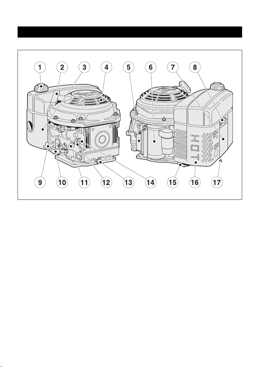
2. Description of the engine
5
Fig 1
1 Fuel tank cap
2 Recoil starter
3 Dry-type air cleaner
4 Intake opening for cooling and
combustion air
5 Voltage regulator
6 Starter motor
7 Noise insulating hood
8 Lifting lug
9 Engine shutdown pin
10 Speed control lever
11 Oil filler pipe
12 Oil filter
13 Oil drain plug
14 Dipstick
15 Exhaust mesh insert
16 Exhaust silencer
17 Type plate
Page 7

3. General notes
3.1. Technical data
1)
These values are intended as an approximate guide. The max. marking on the dipstick is the
determining factor, Fig. 7.
2)
Depending on model (see maintenance charts, chapter 5.1)
3)
Exceeding these limits causes engine breakdown.
Tightening torques
Item Nm
Oil drain plug 50
Type 1B30 V 1B40 V/ W 1B50 V/ W
Design Air-cooled four-stroke diesel engine
Combustion system Direct injection
Number of cylinders 1 1 1
Bore / stroke mm 80 / 69 88 / 76 93 / 76
Displacement
cm
3
347 462 517
Lubricating oil capacity l, approx.
1.1
1)
1.5
1)
1.5
1)
Difference between
„max.“ and „min“ levels
l, approx. 0.5
1)
0.8
1)
0.8
1)
Lubricating oil consumption
after a running-in period
max. 1 % of fuel consumption at full load
Lubricating oil pressure
(oil temperature 100 °C)
approx. 2.5 bar at 3000 r.p.m.
Direction of rotation,
power take-off end
counterclockwise
Valve clearance 10 - 30 °C
Inlet and exhaust valve
mm
0.10 0.10 0.10
or automatically
2)
Max. angle from vertical in any
direction (continuous operation)
25°
3)
Weight (incl. fuel tank, air-cleaner,
exhaust silencer, recoil starter and
electric starter)
kg
approx.
42
1B40 V : 55
1B40 W: 57
1B50 V : 56
1B50 W: 58
Battery capacity max. 12 V / 60 Amp/h
6
Page 8
3.2. Transport
Standard lifting lug „8“ is to allow the
engine and its auxiliaries to be transported safely, chap. 2. It is not suitable or approved for lifting the complete equipment to
which the engine is attached.
3.3. Notes on installation
The „Guide to selecting and installing an engine“
contains all the necessary information on engine
applications if you have an engine which has not
yet been installed in equipment and still has to
be fitted or set up.
This guide is available from your local
HATZ service station.
2
The permitted loads and elements
on the speed adjusting lever and the
engine shutdown pin should be observed as an
excess can lead to damage to the contacts and
inner governor parts.
3.4. Load on engine
See supplemental information for EPA certified
engines, Page 35; resp. supplemental information for California regulations for off road
engines, Page 45.
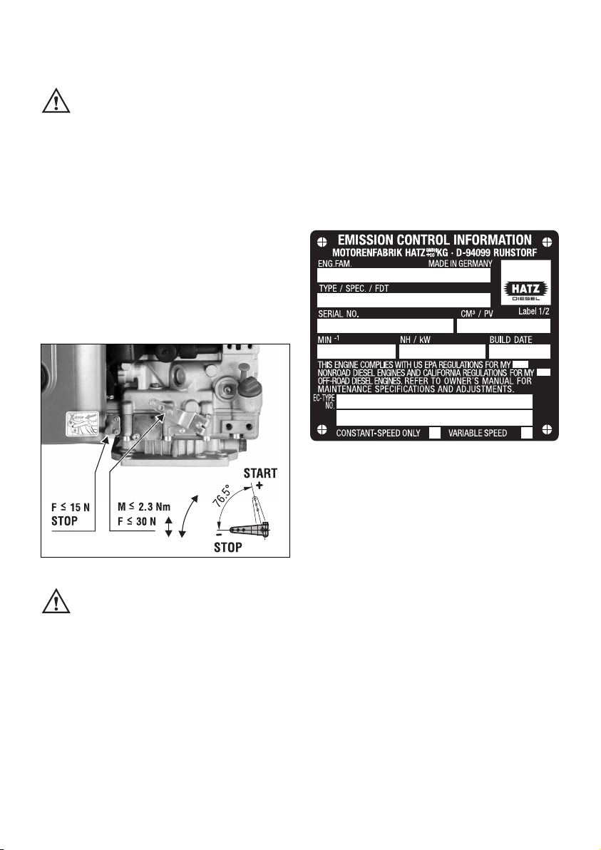
3.5. EPA/CARB-type plates and
fuel label
There are two EPA/CARB- type plates applied
for the identification of the engine. The type
plates are placed on the noise insulating hood
(chapt. 2).
They include the following emission control information (Figure 3a):
Label 1/2
3a
➀ EPA/ CARB - Engine Family Number
➁ engine type / spec. (only for special
equipment) /Fuel Delivery Timing
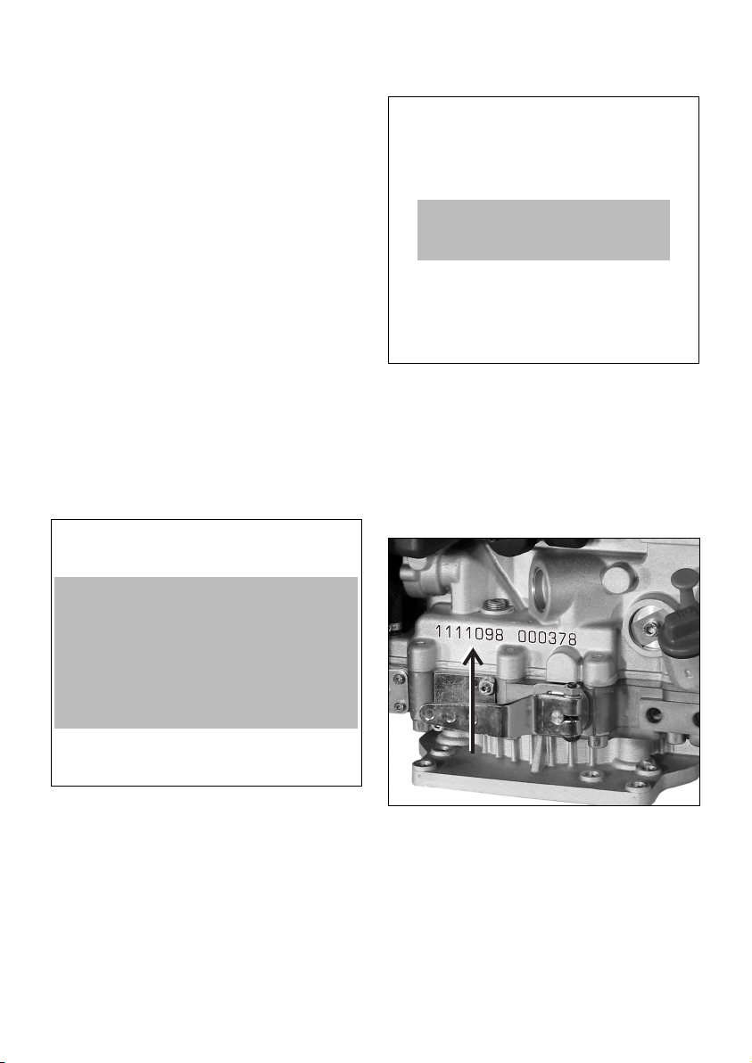
➂ engine number
(also stamped on crankcase, Fig.4)
➃ max. engine rated speed
➄ build date
➅ displacement
➆ rated power
➇ “constant speed only” (if requested)
➈ “variable speed” (if requested)
Every engine is equipped with an additional
loose engine type plate. If the original type
plate on the engine is not readily visible after
the engine is installed in the equipment then
the second loose type plate must be attached
on the equipment in such a manner that it is
readily visible to an average person.
The layout is identical for constant-speed and
variable speed application.
7
➀
➁
➂
➅
➃
➆
➇
➄
➈
Page 9
For any offer as well as spare parts orders it is
necessary to mention the following data (also
see spare parts list, page 1):
➁ engine type / spec.
(only for special equipment)
➂ engine number
➃ max. engine rated speed
Attention:
If the engine was certified for constant-speed
application and shall be used so, the field “constant-speed only” is marked with “X”.
If the engine was certified for variable speed application and shall be used so, the field “variable
speed” is marked with “X”.
Always install the engine for its intended application in order to comply with EPA and CARB
emission regulation requirements.
Label 2/2
3b
The engine must be operated with “LOW SULFUR FUEL OR ULTRA LOW SULFUR FUEL
ONLY”.
The label also states the applicable emissionrelated power category of the engine.
Fuel label
3c
The fuel label is placed nearby the fuel inlet.
If there was no fuel tank mounted to the engine,
the label has to be permanently attached to the
equipment near the fuel inlet.
4
Engine serial number on crankcase.
8
EMISSION CONTROL INFORMATION
LOW SULFUR FUEL OR
ULTRA LOW SULFUR FUEL ONLY
❏ < 8 kW / ❏ 8-19kW / ❏ 19-37kW /
❏ 37-56 kW PM Standard: 0.3 g/kWh
Power category:
Label 2/2
LOW SULFUR FUEL OR ULTRA
LOW SULFUR FUEL ONLY
Page 10
3.6. EMISSION-RELATED
INSTALLATION INSTRUCTIONS
See supplemental information for EPA certified
engines, Page 35; resp. supplemental information for California regulations for off road
engines, Page 45.
3.7. Closed crankcase ventilation
system
Please note that the engine has a closed
crankcase ventilation system.
Exceeding the maximum admissible tilt angle
(see chapter 3.1. Technical data) can cause
damage to the engine.
In cases where the maximum angle is exceeded,
the engine must be stopped immediately.
Before restarting, the engine must be in a horizontal position and the air filter and inlet manifold must be checked for any oil contamination.
If there are any oil contamination, please consult
your nearest HATZ service station.
4. Operation
4.1. Before starting up for the
first time
Engines are normally supplied dry, i.e. not containing fuel or oil.
4.1.1. Engine oil
Oil quality
Qualified are all trademark oils which fulfil at
least one of the following specifications:
ACEA – B2 / E2 or more significant
API – CD / CE / CF / CF-4 / CG-4 or more
significant.
If engine oil of a poorer quality is used, reduce
oil change intervals to 150 hours of operation.
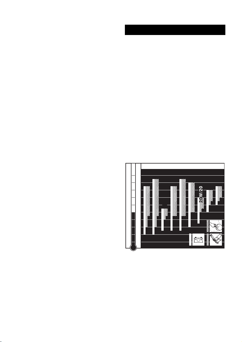
Oil viscosity
5
Select the viscosity class according to the ambient temperature for cold starts.
-40
-30
-20
-10
0
10
20
30
40
50
104
86
68
50
32
14
-4
-22
-40
OIL: SAE...
°C°F
5W/30
5W/40
10W/40
10W/30
15W/40
30
40
122
10 W
9
Page 11
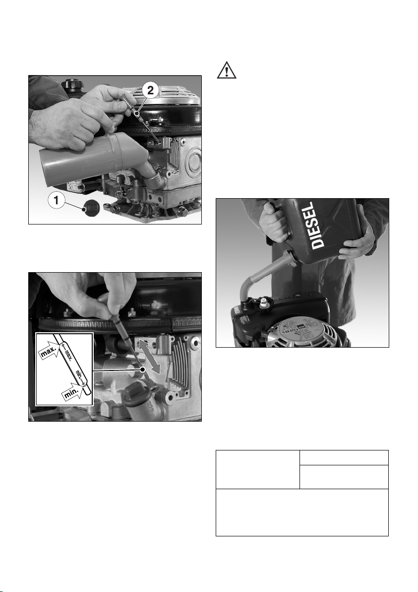
When adding oil or checking the oil level, the
engine must be horizontal.
6
– Remove oil filler screw „1“ and dipstick „2“.
7
– Add engine oil up to the MAX mark on dip-
stick.
Lubricating oil capacity: see Chapter 3.1.
– Insert the oil filler screw and tighten it (hand-
tight only).
4.1.2. Fuel
Stop the engine before refilling the fuel
tank. Never refuel near a naked flame
or sparks which could start a fire.
Don’t smoke. Use only pure fuel and clean
filling equipment. Take care not to spill fuel.
All diesel oils which satisfy the following specifications are suitable:
EN 590 or
BS 2869 A1 / A2 or
ASTM D 975 -1D / 2D
8
– Before the first start or if the fuel tank has
been run dry, completely fill the fuel tank with
diesel. The bleeding of the fuel system is automatically.
At temperatures below 0 °C, winter-grade fuel
should be used or paraffin added to the fuel well
in advance.
Lowest ambient
temperature when
starting, in °C
Paraffin content for:
Summer Winter
fuel fuel
0 up to –10 20 % –
–10 up to –15 30 % –
–15 up to –20 50 % 20 %
–20 up to –30 – 50 %
10
Page 12
4.2. Starting
Do not run the engine in closed or
badly ventilated rooms – danger of poisoning! Before starting the engine, ensure that
no-one is in the danger area close to the engine or equipment, and that all protective
guards are fitted.
4.2.1. Preparations for starting
If possible, disengage the engine from any
driven equipment.
The auxiliary equipment should always be placed
in neutral.
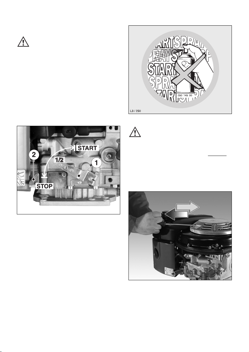
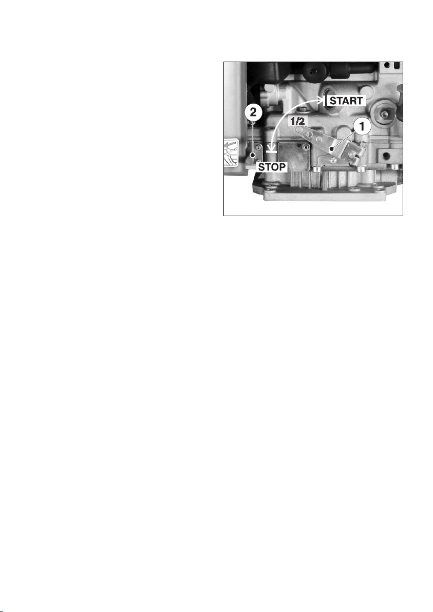
9
– Set speed control lever „1“; First of all put the
lever in STOP-position and then either to
1/2 START or max. START position, as desired
or necessary.
Starting at a lower speed will help to prevent
exhaust smoke.
– Now, the engine is ready for starting.
Important !
After long-time standstill (approx. 6 months or
even longer) or first operation, operate engine
with low adjusted speed and without load for
approx. 20 sec. after start. This measure assures
a lubrication of all bearings before increasing
speed and load.
It also prevents an insufficient lubrication.
10
Never use starting sprays !
4.2.2. Recoil start for versions without
electric starter (till -6 °C)
– For starting preparations, see Chapter 4.2.1.
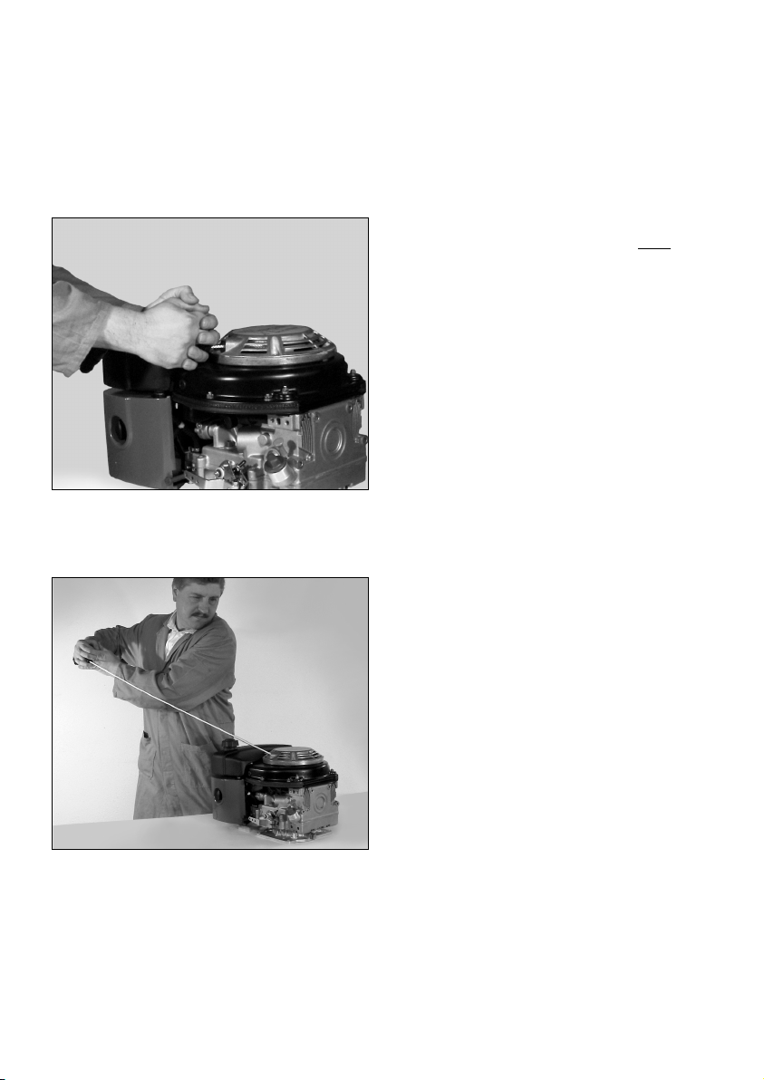
Starting procedure
11
– Pull the starting cable out by the handle until
you feel a slight resistance.
11
Page 13
– Let the cable run back; in this way the entire
length of the starting cable can be used to
start the engine.
– Devices which are not securely fastened
should be restrained with the foot.
12
– Grip the handle with both hands.
13
– Commence pulling the starting cable vigorous-
ly and at an increasing speed (do not jerk it
violently) until the engine starts.
Note:
If after several attempts of starting the exhaust
begins to emit white smoke, move the speed
control lever to the STOP position and pull the
starting cable out slowly 5 times. Repeat the
starting procedure, Chapter 4.2.1.
4.2.3. Recoil start for versions with
electric starter (till -6°C)
The recoil starter at engines with electric start is
an emergency starting device without decom-
pression automatic.
Therefore, attention has to be paid to the exact
starting procedure as mentioned below.
– Prepare the engine for starting;
see Chapter 4.2.1.
– Pull out the handle with the cord slowly until
compression resistance is clearly felt; Fig. 11.
– Continue to pull slowly but with greater force
until the resistance becomes noticeably less
(compression overcome).
– Now let the cord run back - the engine is in
the correct starting position.
In this way the engine can be accelerated
through about one and a half revolutions with
the starting cord, to overcome compression resistance and achieved the required momentum
for starting.
– Support equipment with the foot if it is too
light in weight or liable to tip over.
– Take hold of the handle with both hands;
Fig. 12.
– Pull the starting cord up forcefully and at an
increasing speed (but do not jerk it) - the engine should then start; Fig. 13.
12
Page 14
Note:
In the case of engines with automatic electrical
shutdown system (see next chapter), first
actuate the starter switch from position 0 to
position I, then perform a recoil start within the
following 12 seconds. If the engine does not run
after 12 seconds, this means that the electrical
system blocks the fuel supply to the injection
pump.
In this case, the engine cannot be started.
As a solution, turn the starter key back to posi-
tion 0, then turn it to position I again. Now, start
the engine within the following 12 seconds.
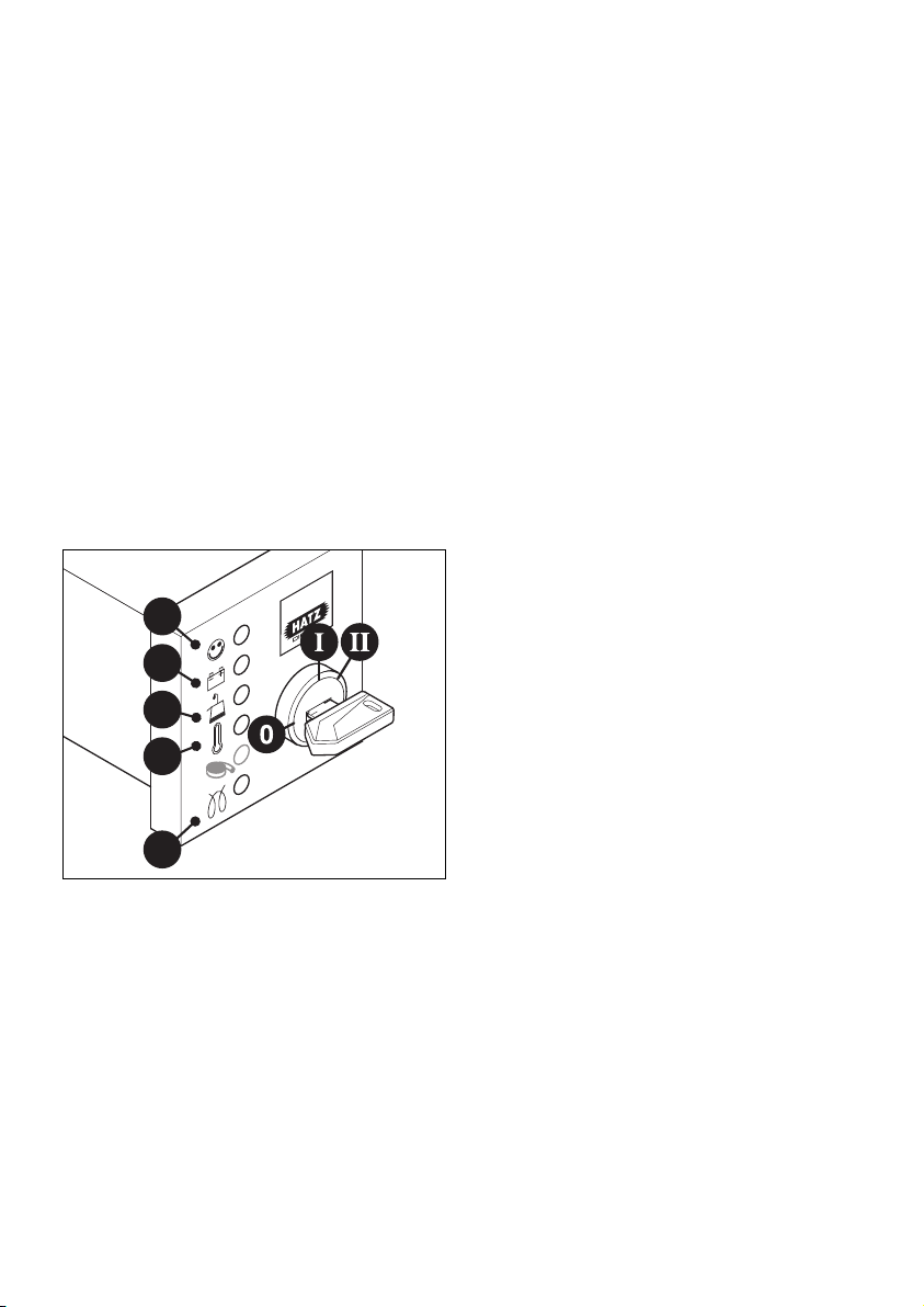
4.2.4. Electric starter
– For starting preparations, see Chapter 4.2.1.
14
– Insert the key to its stop and turn it to
position I.
– Battery charge telltale „2“ and oil pressure
warning „3“ must light up.
– Turn start key to position II.
1
2
3
4
5
– As soon as the engine runs, release the start
key. It must return to position I by itself and
remain in this position during operation.
The battery charge telltale and oil pressure
warning must go out immediately after starting. Indicator light „1“ is on when the engine
is in operation.
– The engine temperature display „4“ (additional
equipment) lights up if the temperature at the
cylinder head becomes too high.
Switch off the engine and trace and eliminate the cause of the problem, chap. 6.
– Always turn the start key back to position 0
before re-starting the engine. The repeat lock
in the ignition lock prevents the starter motor
from engaging and possibly being damaged
while the engine is still running.
Preheating device with automatic heating
timer (additional equipment)
The preheating light „5“ lights up additionally at
temperatures below 0° Celsius (Fig. 14).
– After the light has gone out, start the engine
without delay.
13
Page 15
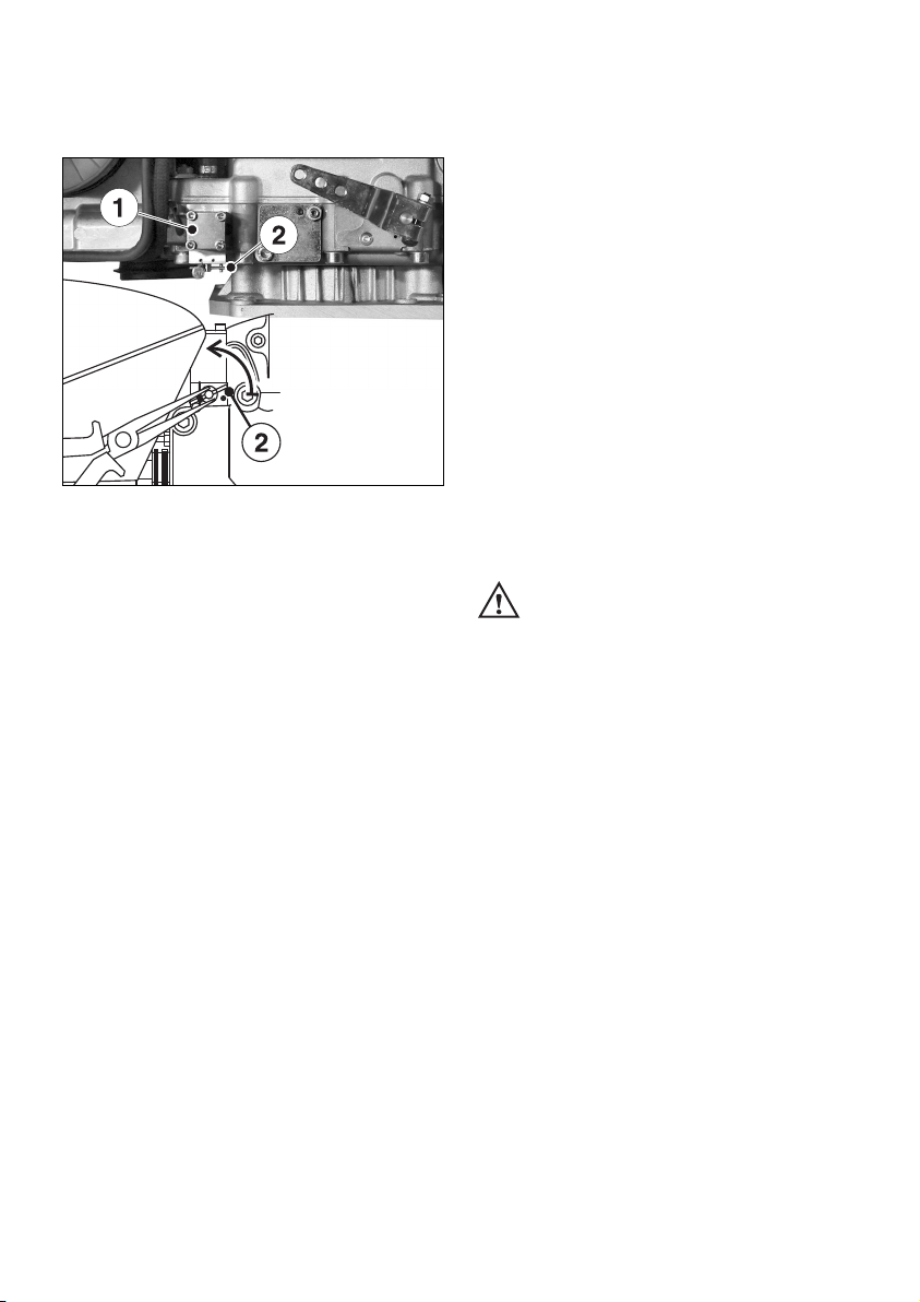
Fuel shut-off valve, stop solenoid
(additional equipment)
15
As soon as the starting key is at Position I,
fuel shut-off valve „1“ is electrically released.
The fuel feed to the injection pump is then open
and the engine is ready to start.
When the engine is running, turning the starting
key to position 0 closes the shut-off valve and
interrupts the fuel supply to the injection pump,
so that the engine stops; Chapter 4.3.
This shut-off valve is also used for the automatic
electrical shutdown system.
Emergency start
If the shut-off valve is blocking the fuel supply
as a result of an electrical fault and the engine
therefore cannot be started, an emergency start
can be attempted.
Proceed as follows for this:
– For emergency starting, turn the lever at fuel
shut-off solenoid „2“ anti-clockwise by at least
90° using suitable pliers. The lead seal wire
will break off.; Fig. 15.
– As soon as the emergency start lever is in the
starting position, the electric starter or recoil
starter can be used; Chapter 4.2.2 and 4.2.3.
The oil level must always be checked before an
emergency start, as insufficient oil pressure
can lead to complete damage of the engine
within a very short time.
After this, the engine can only be
stopped with the starting key in the
emergency operating mode if the emergency
starting lever is first turned back clockwise to
the stop position.
Immediately after a period of emergency
running, ascertain the cause of the fault and
have it rectified; Chapter 6.
Have the emergency-starting lever sealed once
again by a HATZ service point.
When the automatic electrical shutdown system
is used, the emergency start described above
means that liability for risks must be accepted
by the operator (Motorenfabrik HATZ assumes
no liability) !
In case of difficulty contact the nearest HATZ
service point.
14
Page 16
Automatic electrical shutdown system
(additional equipment)
This is characterized by a brief flashing of all
pilot lamps once the starter key has been turned
to position I (Fig. 14).
Important !
If the engine cuts out immediately after starting
or switches off by itself during operation, a
monitoring element in the automatic shutdown
system has tripped. The corresponding indicator
light (Fig. 14, positions 2 - 4) will come on.
After the engine has stopped, the display continues to glow for about 2 minutes.
The electrical device then switches itself off automatically.
The display lights up again after the start key
has been turned back to position 0 and then to
position I again.
Trace and eliminate the cause of the operating
fault before trying to restart the engine
(see chapter 6.2.).
The display light goes out when the engine is
next started.
Even with automatic shutdown monitoring
the oil level must be checked every 8 – 15
operating hours (Chapter 5.2.1.).
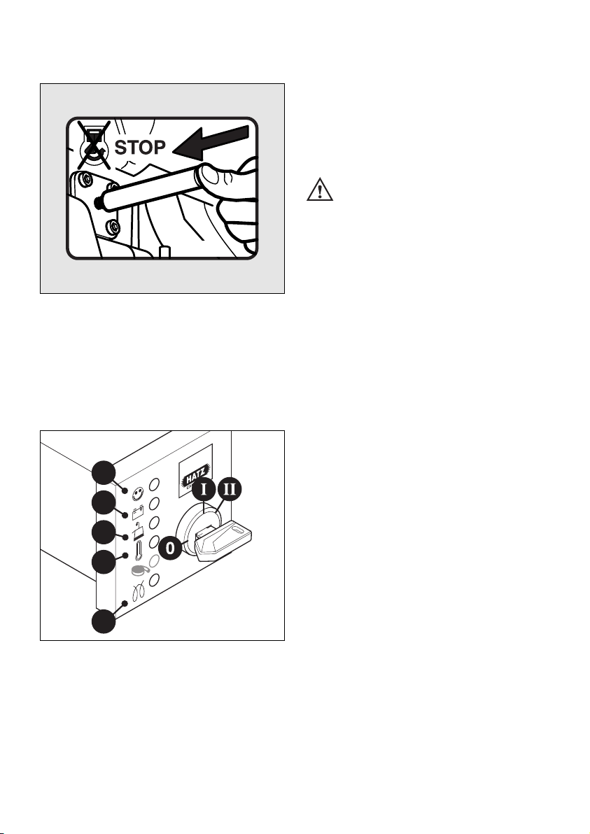
4.3. Stopping the engine
16
– Move the speed adjustment lever „1“ back
to the STOP position. The engine cuts out.
Note:
Engines with a fixed lower idling speed cannot
be switched off using the speed adjustment
lever. See the paragraph entitled „Other ways of
switching off the engine“.
Other ways of switching off the engine
1. Fuel shut-off valve, stop solenoid
(optional extra)
– Turn ignition key to the 0 position. The engine
cuts out, Fig. 18.
15
Page 17
2. Stop pin (optional extra)
17
– Press the stop pin „2“ until the engine cuts out
(see also Fig. 16, pos. 2).
– Once the engine has cut out, release the
pin „2“ and ensure that it returns to its initial
position, Fig. 16.
18
Depending upon the model, the battery charge
indicator „2“ and oil pressure warning indicator
„3“ will come on again after the engine comes to
a stop.
1
2
3
4
5
05221301
– Turn the key to position 0 and remove it.
All the indicator lights must go out.
Note:
Failure to return the starter key to position 0
may result in the battery being totally
discharged.
If operation of the engine is inter-
rupted for any reason, or at the end of
the working day, the starter key should be kept
out of reach of unauthorised persons.
16
Page 18

5. Maintenance
Only carry out maintenance work with the engine switched off.
Observe all relevant laws and regulations governing the handling and disposal of used oil,
filters and cleaning agents.
Protect the starting key against unauthorised use.
On engines with an electric starter, disconnect the battery’s negative terminal.
When maintenance work has been completed, check that all tools have been removed from the
engine and all protective guards fitted again.
Before starting the engine, ensure that there are no persons in the danger area close to the engine or equipment.
5.1. Maintenance chart
Maintenance interval Maintenance work required Chap.
17
Every 8 – 15
operating hours,
or before each daily
start-up
Check oil level.
Check combustion and cooling air intake zone.
Check air-cleaner maintenance indicator.
5.2.1.
5.2.2.
5.2.3.
Every 250
operating hours
Change engine oil.
Check and adjust valve clearances. (Not applicable with automatic self adjusting valve clearance
models, see next page)
Clean cooling air area.
Check screw connections.
Clean mesh insert for exhaust.
5.3.1.
5.3.2.
5.3.3.
5.3.4.
5.3.5.
Every 500
operating hours
Change fuel filter element.
Dry-type air cleaner maintenance.
5.4.1.
5.4.2.
Every 1000
operating hours
Clean the oil filter.
5.5.1.
Once a year
Siphon water out of fuel tank.
5.6.1.
8-15
250
500
1000
Page 19

Depending whether the engine is equipped with
or without automatic valve clearance adjustment
one of the illustrated maintenance plans is included. This label should be affixed to the engine
or equipment in an easily visible position. The
maintenance chart governs the maintenance intervals.
On new or reconditioned engines, after the
first 25 operating hours, always
– Change engine oil, Chapter 5.3.1.
– Check valve clearances and adjust if
necessary, Chapter 5.3.2.
– Examine screw connections, chapter 5.3.4.
Do not tighten the cylinder head fastening.
If the engine is not used frequently, change the
engine oil after 12 months at the latest, regardless of the actual number of hours it has been in
operation.
18
Model without automatic valve clearance adjustment.
Model with automatic valve clearance adjustment.
Page 20

5.2. Maintenance every 8 – 15
operating hours
5.2.1. Checking engine oil level
To check the oil level, the engine must be
standing level and be switched off.
– Remove any dirt from the oil dipstick area.
19
– Check the dipstick oil level and, if necessary,
add oil to the max. mark, Chapter 4.1.1.
5.2.2. Check air intake area for
combustion and cooling
Heavy contamination is an indication that increased dust accumulation necessitates a
correspondingly shorter maintenance interval,
Chapter 5.3.3. and 5.4.2.
20
– Check air intake points „1“ for severe blockage
due to leaves, heavy dust accumulation etc.,
and if necessary clean them.
5.2.3. Check air cleaner maintenance
indicator (optional extra)
Mechanical service indicator
21
– Increase the speed of the engine briefly to the
maximum. If the rubber bellows shrinks and
covers the green area „1“, the air cleaner system should be serviced, Chapter 5.4.2.
Under dusty conditions, check the rubber
bellows several times per day.
19
Page 21

5.3. Maintenance every 250
operating hours
5.3.1. Changing engine oil
The engine must be standing level and be
switched off.
Only change the oil when the engine is warm.
Danger of scalding from hot oil !
Trap the old oil and dispose of it in
accordance with local legislation.
22
– Take out oil drain plug „1“ and allow the oil to
drain out.
– Clean the oil drain plug „1“, fit a new washer
„2“, insert and tighten.
– Add engine oil, Chapter 4.1.1.
5.3.2. Checking and adjusting valve
clearances
Remark:
Following steps are inapplicable in case equipment is with automatic tappet clearance compensation. Identification characteristic is maintenance plan, chapter 5.1.
Only carry out adjustments when the engine is
cold (10 - 30 °C).
23
– Remove air cleaner cover.
24
– Remove noise insulating hood.
20
Page 22

– Remove any contamination adhering to the
cover for the cylinder head.
25
– Remove screws „1“ and take off the cylinder
head cover with gasket „2“.
26
– Remove rubber cap from the inspection hole
cover.
– Turn the engine over in the normal direction
of rotation until the valves are in the overlap
position (exhaust valve not yet closed, inlet
valve starts to open).
– Turn the crankshaft through 360° in the
normal direction of rotation and align exactly
to the OT-marking, Figure 26.
27
– Check valve clearances with feeler gauge „1“.
– If valve clearances require adjusting, slacken
off screw „2“ and turn hex nut „3“ until feeler
gauge „1“ can be pulled through with just
slight resistance when screw „2“ is retightened.
– Fit cover for cylinder head and tighten evenly,
always using a new gasket.
– Re-attach parts previously removed from en-
gine.
Do not forget: replace the rubber cap at the
inspection hole cover.
– Carry out a brief test run, then check the cover
for leaks.
21
Page 23

5.3.3. Cleaning the air cleaner zone
The engine must be switched off and
cooled down before cleaning !
– If severely contaminated, clean the cooling fins
on the cylinder and cylinder head, and also the
fan blades in the flywheel. If necessary, contact your local HATZ service station.
5.3.4. Checking screw connections
– Check the tightness of all threaded connec-
tions and take up slack if necessary, provided
that these can be reached during maintenance
work.
Do not tighten the cylinder head bolts.
28
The adjusting screws at the engine
governor and on the injection system
are sealed with lacquer and are not to be
tightened or adjusted.
5.3.5. Cleaning the exhaust mesh inlet
Exhaust system components will
naturally be hot and must not be
touched while the engine is running or until it
has cooled down after being stopped.
29
– Unscrew hex nut and remove the exhaust
mesh insert.
– Remove any deposits in the mesh insert by
means of a wire brush.
– Check the exhaust mesh insert for cracks or
damage and, if necessary replace with a new
one.
22
Page 24

30
– Screw on hexagon nut „1“ by approx. 1 turn.
31
– Insert exhaust screen with hoop „1“ into hole,
them pull outwards again so that the hoop is
retained.
– Tighten the hexagon nut fully.
5.4. Maintenance every 500
operating hours
5.4.1. Renewing fuel filter
The maintenance intervals for the fuel pump
filter are dependent upon the purity of the diesel
oil being used and, if necessary, may have to be
reduced to 250 hours.
When working on the fuel system, do
not expose it to naked flames; do not
smoke.
Important !
Keep the entire area clean so that no dirt
reaches the fuel. Fuel particles may damage
the injection system.
32
– Open tank cap and pull out fuel filter from tank
with cord.
23
Page 25

33
– Pull fuel supply line „1“ off fuel filter „2“ and
insert new filter.
– Fit the fuel filter again and close the tank cap.
Bleeding of the fuel injection system takes
place automatically.
5.4.2. Air cleaner maintenance
The filter cartridge should only be cleaned when
the maintenance lamp lights at maximum speed,
chap. 5.2.3.
However, the filter cartridge should always be
replaced after 500 operating hours at the latest.
34
– Remove the air cleaner cover.
35
– Unscrew and remove knurled nut „1“ and take
off air cleaner element „2“.
– Clean the filter compartment and the cover.
Dirt and other foreign bodies must not be
allowed to enter the engine’s air inlet points.
24
Page 26

36
– On versions with a mechanical air cleaner
service indicator, check the condition and
cleanliness of valve plate „1“.
– The filter cartridge should either be renewed
or, depending upon the degree of contamination, cleaned, or checked, as follows:
Cleaning the filter cartridge
Dry contamination
37
– Use compressed air to blow through the filter
cartridge from the inside outwards, until no
further dirt emerges.
Important !
The pressure must not exceed 5 bar.
Moist or oily contamination
Renew the filter cartridge.
Checking the filter cartridge
– Check filter cartridge’s gasket surface „1“ for
damage, Fig. 37.
– Check the filter cartridge for cracks or any
other type of damage to the paper filter by
holding it inclined towards the light or by
shining a light source through it.
Important !
The slightest damage to the paper filter rules
out it being used any longer.
– Re-assemble the filter cartridge in the reverse
order of work.
25
Page 27

5.5. Maintenance every 1000
operating hours
5.5.1. Cleaning the oil filter
Cleaning of oil filter should be carried out
together with changing engine oil.
The engine must be standing level and be
switched off.
Danger of scalding from hot oil !
Trap the old oil and dispose of it in
accordance with local legislation.
38
– Loosen screw „1“ with approx. 5 rotations.
39
– Remove oil filter from housing.
40
– Use an air line to blow out oil filter dirt from
the inside outwards.
26
Page 28

41
– Check joint washer „1“ whether it is damage;
replacement if necessary.
– Check joint washer „2“ whether it is damage
and correctly fitted, replace oil filter if
necessary.
– Lubricate joint washer before fitting.
42
– Put in oil filter and press until limit stop.
– Check whether tension springs sit close to oil
filter with both ends „1“, before tightening
screw.
– Check the dipstick oil level and, if necessary,
add oil to the max. mark, Chapter 4.1.1.
5.6. Servicing: once a year
5.6.1. Draining the fuel tank
When working on the fuel system, do
not expose it to a naked flame;
do not smoke.
– Condensation forms due to temperature varia-
tions at the lowest points of the fuel tank.
The condensate must therefore be removed once
a year as follows:
43
– Fit a polyethylene tube ( diameter 4 mm,
length approx. 350 mm) to a commercial
syringe (20 ml or larger).
27
Page 29

44
– Run the tube down to the bottom of the tank
and drain off the diesel oil/water mixture.
The specific gravity of water is heavier than
that of diesel oil and therefore a distinct
dividing line should be visible.
– Repeat the procedure several times until the
transparent syringe is full of diesel oil only.
28
Page 30

29
6. Malfunctions – causes and remedies
Malfunctions Possible causes Remedy Chap.
6.1.
Engine does not
start, or not immediately, but can be
turned over easily
as usual.
At low
temperatures.
Speed control lever in stop or
idle position.
Engine shutdown pin in STOP
position.
No fuel in the injection pump.
Insufficient compression:
- Incorrect valve clearance.
- Cylinders and/or piston rings
worn.
Injector not functioning.
Below starting threshold
temperature.
Equipment not disengaged.
Preheating system faulty
(optional extra).
Fuel has inadequate resistance
to low temperatures.
Move lever to START position.
Move to operating position by
pulling the pin gently.
Add fuel.
Systematically check the entire
fuel supply system: If still no
fault found,
- check engine feed line
- check fuel filter
Check valve clearances, adjustif
necessary.
See workshop manual.
See workshop manual.
Operate preheater
(optional extra).
Disengage engine from equipment, if possible.
See workshop manual.
Check whether clear (not turbid)
fuel emerges at the fuel line detached from the injection pump.
If turbid or separated - either
warm up the engine or drain the
complete fuel supply system.
Refill with winter-grade fuel to
which paraffin has been added.
4.2.1.
4.3.
4.1.2.
5.4.1.
5.3.2.
4.2.4.
4.1.2.
Page 31

Malfunctions Possible causes Remedy Chap.
30
At low
temperatures
If equipped with a
stop solenoid or
automatic electrical shutdown system (additional
equipment)
6.2.
Engine fires but
does not run.
With automatic
shutdown
(optional extra)
6.3.
Starter motor does
not operate or
engine does not
turn over.
Starting speed below 400 rpm:
- Viscosity of oil too high.
- Battery charge too low.
Solenoid faulty and/or fault in
the electrical system.
Speed control lever not moved
far enough towards „START“.
Equipment not disengaged.
Fuel filter blocked.
One of the automatic shutdown’s monitoring elements
has initiated a stop signal.
(See also Chapter 6.4.).
Fault in the electrical system:
- Battery and/or other cables
incorrectly connected up.
- Cable connections loose
and/or oxidised.
- Battery faulty and/or flat.
- Starter motor faulty.
- Faulty relays, monitoring
element.
Change lubricating oil and add
oil of the correct viscosity class.
Check the battery, if necessary
contact a service station.
See workshop manual.
Move lever to „START“ position.
Disengage engine from equipment if possible.
Renew fuel filter.
Localise the monitoring element
responsible and clear the fault,
or contact a HATZ service
station.
Check electrical system and its
component.
See also the workshop manual.
5.3.1.
4.1.1.
7.
4.2.1.
5.4.1.
7.
Page 32

Malfunctions Possible causes Remedy Chap.
31
6.4.
Engine cuts out of
its own accord
during operation.
With automatic
electrical shutdown installed
(optional extra)
6.5.
Engine output and
speed both drop.
Fuel supply interrupted
- Tank has run empty.
- Fuel filter blocked.
- Aeration outlet restricted at
fuel tank seal.
- Air in the fuel system.
Mechanical faults.
One of the automatic shutdown’s monitoring elements
has initiated a stop signal.
Monitoring element for:
- oil pressure too low
- engine temperature too high
- defective alternator.
Fuel supply interrupted:
- Tank has run empty.
- Fuel filter blocked.
- Aeration outlet restricted
at fuel tank seal.
- Air in the fuel system.
- Speed control lever does not
remain in desired position.
Add fuel.
Change fuel filter.
Ensure adequte tank venting.
Check fuel system for
penetration of air.
Check air vent valve.
Contact a HATZ service station.
Localise the monitoring element
responsible and clear the fault,
or contact a HATZ service
station.
Check oil lubrication.
Check air cooling zone for
contamination.
See workshop manual.
Add fuel.
Change fuel filter.
Provide adequate tank breathing.
Check fuel system for
penetration of air.
Check air vent valve.
Lock the lever into position.
4.1.2.
5.4.1.
5.2.1.
5.3.3.
4.1.2.
5.4.1.
Page 33

32
Malfunctions Possible causes Remedy Chap.
6.6.
Engine output
and speed fall,
black smoke
from exhaust.
6.7.
Engine becomes
very hot. Indicator
lamp for cylinder
temperature
(optional extra)
comes on.
6.8.
Condensate outlet
from exhaust box.
Air cleaner contaminated.
Valve clearances incorrect.
Injector not functioning.
Too much lubricating oil in
engine.
Inadequate cooling:
- Contamination of entire
cooling air zone.
- Air duct panels not properly
sealed.
Operation over a longer period
without load.
Clean or renew the air cleaner.
Adjust valve clearances.
See workshop manual.
Drain off lubricating oil as far as
upper mark on dipstick.
Clean cooling air zone.
Check cooling air deflector
plates and shafts for completeness and airtight seal.
Run engine with a load of 70%
until the exhaust box gets dry
again.
5.4.2.
5.3.2.
5.3.1.
5.3.3.
Page 34

7. Work on the electrical
system
Batteries generate explosive gases.
Keep them away from naked flame and
sparks which could cause them to ignite.
Do not smoke.
Protect eyes, skin and cloth against the corrosive battery acid. Pour clear water over acid
splashes immediately. In case of emergency
call doctor.
Do not place any tools on top of the battery.
Always disconnect the negative (–) pole of the
battery before working on the electric device.
– Do not confuse the positive (+) and
negative (–) terminals of the battery.
– When fitting the battery, first connect up the
positive lead, then the negative lead.
Negative terminal to earth = engine block.
– When removing, first disconnect the negative
lead, then the positive lead.
– Always take care to avoid short-circuits and
earth (ground) contact of live cables.
– If malfunctions occur, first of all check that
cable connections make good contact.
– Replace a failed indicator light without delay.
– Do not remove the ignition key while the en-
gine is running.
– Do not disconnect the battery while the en-
gine is running. Electric voltage peaks can
cause damage to electrical components.
– In case of an emergency start in manual
mode, leave the battery (which might be discharged) connected to the engine.
– For emergency operation without battery,
make sure that the plug-and-socket connector
to the instrument box is disconnected additionally before the engine is started.
– Do not splash electrical device with water jet
or pressure jet during engine cleaning.
– When carrying out welding work on the en-
gine or equipment, fit the earth clip of the
welding equipment as close to the welding
point as possible and disconnect the battery.
The connecting plug for the voltage regulator
must be removed.
The relevant circuit diagrams are enclosed with
the engine if it is equipped with an electrical
system. Additional circuit diagrams can be
supplied to order.
HATZ assumes no liability for electrical systems
which was not carried out acc. HATZ circuit diagrams.
8. Storage out of use
The new engine can normally be stored dry for
up to one year.
In very humid climates or coastal regions, the
protective treatment is sufficient for up to about
6 months.
For longer periods of storage, please contact
your nearest HATZ service station.
33
Page 35

Page 36

SUPPLEMENTAL INFORMATION
TO THE OWNER'S MANUAL FOR 2008 AND LATER
EPA CERTIFIED
NONROAD COMPRESSION IGNITION ENGINES.
EPA EMISSION CONTROL SUPPLEMENTAL
WARRANTY STATEMENT AND
EMISSION-RELATED INSTALLATION
INSTRUCTIONS.
35
Page 37

MAINTENANCE AND WARRANTY.
SUPPLEMENTAL INFORMATION TO THE OWNERS MANUAL FOR 2008 AND
LATER EPA CERTIFIED NONROAD COMPRESSION IGNITION ENGINES.
The following supplemental information is furnished for EPA Nonroad Compression
Ignition Engines which are certified according to 40 CFR Part 89 and Part 1039.
This information contains the following specific items:
• EPA-related engine parts and engine operating conditions
• Maintenance instructions for EPA-related engine parts
• Emission control system and adjustments
• Warranty statement
• Emission-related installation instructions
ENGINE PARTS AND / OR EQUIPMENT RELATED TO EPA EXHAUST
EMISSION REGULATIONS.
Parts which are mandatory for engine operation.
The following parts as manufactured according to HATZ specifications are mandatory for
engine operation which meets EPA exhaust emission regulations.
• Fuel injection pump
• Injection nozzle
• Bimetallic strip
• Crankcase breather valve assembly
• Air cleaner housing
36
Page 38

• Oil filler cap
• Intake and exhaust gaskets at head interfaces
• Emission Control Information Labels
Only parts manufactured by Hatz and which have passed the Hatz Quality Assurance
Program are assured of meeting EPA exhaust emission regulations.
UNUSUAL OPERATING CONDITIONS.
The engine must not be operated at a load factor less than 25 % for an extended period as
such operation will cause the fuel injector to foul. If such a condition occurs, you should
contact the nearest HATZ authorized Service Center for necessary repairs.
The engine is designed and adjusted to operate most efficiently at the following
conditions:
• Air temperature of 25° C ( 77° F)
• Atmospheric pressure of 100 kPa (14.5 psi)
• Relative humidity of 30 %
Operation of the engine at conditions other than above will affect performance and
exhaust emissions. Normally the equipment manufacturer takes this into account during
the design of the machine and your equipment will perform within specifications over a
wide range of climatic conditions. However if you must operate your equipment under
very unusual climatic conditions, please contact your nearest Hatz distributor for advice.
37
Page 39

MAINTENANCE SCHEDULE-EPA-RELATED PARTS
The following minimum intervals are being adopted for adjustment, cleaning, repair, or
replacement of following components:
At 1,500 hours, and 1,500-hours intervals thereafter:
• Fuel injector tips (cleaning only)
At 3,000 hours, and 3,000-hours intervals thereafter:
• Fuel injector
The exhaust quality of the engines can be influenced by the execution (the quality of
execution) of above described maintenance work.
Therefore, the maintenance work has to be carried out by a qualified workshop.
Hatz authorised workshops, for example, are qualified workshops.
Hatz Diesel of America will give you respective addresses, if required.
EMISSION CONTROL SYSTEM AND ADJUSTMENTS.
The emission control system for this engine is EM (Engine Modification).
No adjustments are needed or possible.
38
Page 40

EPA EMISSION CONTROL WARRANTY STATEMENT
YOUR WARRANTY RIGHTS AND OBLIGATIONS.
Motorenfabrik Hatz GmbH & Co. KG warrants the emission control system on your
engine for the periods of time listed below provided there has been no abuse, neglect or
improper maintenance of your engine.
Your emission control system includes:
• Fuel injection pump
• Injection nozzle
• Bimetallic strip
• Crankcase breather valve assembly
• Air cleaner housing
• Oil filler cap
• Intake and exhaust gaskets at head interfaces
• Emission Control Information Labels
Where a warrantable condition exists, Motorenfabrik Hatz will repair your engine at no
cost to you including diagnosis, parts and labor.
MANUFACTURERS WARRANTY COVERAGE:
The 2008 and later EPA certified nonroad compression ignition engines are warranted for
1500 hours of operation or two years of use, whichever first occurs.
If any emission related part on your engine is defective, the part will be repaired or
replaced by Motorenfabrik Hatz.
39
Page 41

OWNERS WARRANTY RESPONSIBILITIES:
• As the engine owner, you are responsible for the performance of the required
maintenance listed in your owner's manual. Motorenfabrik Hatz recommends that you
retain all receipts covering maintenance on your engine, but Motorenfabrik Hatz cannot
deny warranty solely for the lack of receipts or for your failure to ensure the
performance of all scheduled maintenance.
• As the engine owner, you should be aware, however, that Motorenfabrik Hatz may
deny you warranty coverage if your engine or a part has failed due to abuse, neglect,
improper maintenance or unapproved modifications.
• You are responsible for presenting your engine to a Motorenfabrik Hatz authorized
service center as soon as a problem exists. The warranty repairs should be completed in
a reasonable amount of time, not to exceed 30 days.
If you have any questions regarding your warranty rights and responsibilities, you should
contact HATZ DIESEL OF AMERICA, Inc. at (262) 544-0254.
HATZ DIESEL SUPPLEMENTAL WARRANTY FOR 2008 AND LATER EPA
CERTIFIED ENGINES.
PARTS WITH SUPPLEMENTAL LIMITED WARRANTY.
The following limited warranty is supplemental to the standard HATZ DIESEL LIMITED
ENGINE WARRANTY and covers 2008 and later EPA certified engines and applies to
the following exhaust emission-related components:
• Fuel injection pump
• Injection nozzle
• Bimetallic strip
• Crankcase breather valve assembly
• Air cleaner housing
• Oil filler cap
• Intake and exhaust gaskets at head interfaces
• Emission Control Information Labels
40
Page 42

SUPPLEMENTAL LIMITED WARRANTY.
Hatz Diesel of America, Inc. hereinafter referred to as “HATZ” warrants each of the
above-listed parts when installed in a new engine sold by Hatz to be free from defects in
material and workmanship under normal use and service, only under the named warranty
coverage conditions, after the date of delivery to the original retail purchaser and Hatz
will at their option, repair or replace at Hatz's sales headquaters, or at a point designated
by Hatz, any part or parts which shall appear to the satisfaction of Hatz upon inspection at
such point, to have been defective in material or workmanship.
• Any warranted part which is scheduled for replacement as required maintenance is
warranted for the period of time up to the first scheduled replacement point for that
part.
• Any replacement part which is equivalent in performance and durability may be used in
non-warranty maintenance or repairs and will not reduce the overall engine warrranty
obligations of Hatz. However, Hatz is not responsible for failure of such replacement
parts or failure of any other parts directly caused by failure of such replacement parts.
• This warranty does not obligate Hatz to bear any transportation charges in connection
with the repair or replacement of defective parts. This warranty is transferrable to
subsequent owners, only under the named warranty coverage conditions.
• In order to obtain service under this warranty, the retail purchaser should contact Hatz
Diesel of America, Inc. at (262) 544-0254 for information and the nearest service
center. The retail purchaser will not be charged for diagnostic labor which leads to the
determination that a warranted part is defective, nor for the repair or replacement of
warranted parts if the work is performed at an authorized Hatz service center. If other
engine components are damaged due to a failure of the above-listed warranted parts
still under warranty, these other engine components will also be repaired or replaced at
no charge.
• This warranty shall not apply to any engine which shall have been installed or
operated in a manner not recommended by Hatz, nor to any engine which shall have
been repaired, altered, neglected, or used in any way which, in the opinion of Hatz,
adversely affects its performance, nor to any engine in which parts not authorized by
Hatz have been used, which parts or the use of which have damaged or caused defects
in or otherwise adversely affected the engine or its performance, nor to normal
maintenance service or replacement of normal service items.
Hatz reserves the right to modify, alter, and improve any engine or parts without incurring
any obligation to replace any engine or parts previously sold with such modified, altered,
or improved engine or parts.
41
Page 43

EMISSION-RELATED INSTALLATION INSTRUCTIONS
“Failing to follow these instructions when installing a certified engine in a piece of
nonroad equipment violates federal law (40CFR1068.105(b)), subject to fines or other
penalties as described in the Clean Air Act.”
“If you install the engine in a way that makes the engine's emission control information
labels hard to read during normal engine maintenance, you must place duplicate labels on
the equipment.”
EQUIPMENT-LABELLING REQUIREMENTS: FUEL LABEL (Chapter 3.5)
The fuel label has to be permanently attached to the equipment.
In case of an engine mounted fuel tank, every engine is equipped with an additional fuel
label.
Otherwise, there are two loose fuel labels available with the engine.
If the original fuel label is not readily visible after the engine is installed in the equipment
then the second loose fuel label must be attached on the equipment in such a manner that
it is readily visible to an average person.
42
Page 44

INSTRUCTIONS ON THE INSTALLATION OF THE EXHAUST SYSTEM
Following are the instructions to properly install the exhaust system and related
components consistent with the EPA emission regulation requirements.
Exhaust-silencers and protection guard
The exhaust silencer is fitted in connection with flat washers.
Fixation is done by Allen screws.
43
1B30 V · 1B40 V/W · 1B50 V/W
1
2
3
4
4
Page 45

Dismantling:
• Remove in numerical sequence 1...4.
Assembly:
• Assemble in reverse sequence.
• Ensure gasket-kit is fitted in correct sequence i.e. the creased gaskets 4 face towards
exhaust silencer and cylinder head.
SAMPLING OF EXHAUST EMISSIONS
After the engine is installed in the equipment and placed in service, the sampling of
exhaust emissions can be performed in a way that prevents diluting the exhaust sample
with ambient air as follows:
• Remove the exhaust mesh insert, if so fitted, as described in chapter 5.3.5.
• The sampling probe for measuring the emissions can be put into the exhaust silencer
outlet. There are no additional pipes or clamps needed for measuring the undiluted
exhaust sample.
44
Page 46

SUPPLEMENTAL INFORMATION
TO THE OWNER´S MANUAL
FOR 2008 AND LATER
CALIFORNIA REGULATIONS FOR
HEAVY-DUTY OFF-ROAD ENGINES
CALIFORNIA EMISSION CONTROL
WARRANTY STATEMENT AND
EMISSION-RELATED INSTALLATION
INSTRUCTIONS.
45
Page 47

MAINTENANCE AND WARRANTY.
SUPPLEMENTAL INFORMATION TO THE OWNER´S MANUAL FOR 2008
AND LATER CALIFORNIA REGULATIONS FOR HEAVY-DUTY OFF-ROAD
ENGINES.
The following supplemental information is furnished for California Heavy-Duty Off-Road
Engines.
This information contains the following specific items:
• CARB-related engine parts and engine operating conditions
• Maintenance instructions for CARB-related engine parts
• Emission control system and adjustments
• Warranty statement
• Emission-related installation instructions
ENGINE PARTS AND / OR EQUIPMENT RELATED TO CARB EXHAUST
EMISSION REGULATIONS.
Parts which are mandatory for engine operation.
The following parts as manufactured according to HATZ specifications are mandatory
for engine operation which meets CARB exhaust emission regulations.
• Fuel injector
• Fuel injection pump
• Bimetalic Strip
• Intake manifold
• Exhaust manifold
• Crankcase breather valve
46
Page 48

• Oil filler Cap
• Intake and exhaust gaskets at head interfaces
• Emission Control Information Labels
Only parts manufactured by Hatz and which have passed the Hatz Quality Assurance
Program are assured of meeting CARB exhaust emission regulations.
UNUSUAL OPERATING CONDITIONS.
The engine must not be operated at a load factor less than 25 % for an extended period as
such operation will cause the fuel injector to foul. If such a condition occurs, you should
contact the nearest HATZ authorized Service Center for necessary repairs.
The engine is designed and adjusted to operate most efficiently at the following conditions:
• Air temperature of 25° C ( 77° F)
• Atmospheric pressure of 100 kPa (14.5 psi)
• Relative humidity of 30 %
Operation of the engine at conditions other than above will affect performance and
exhaust emissions. Normally the equipment manufacturer takes this into account during
the design of the machine and your equipment will perform within specifications over a
wide range of climatic conditions. However if you must operate your equipment under
very unusual climatic conditions, please contact your nearest Hatz distributor for advice.
47
Page 49

MAINTENANCE SCHEDULE-CARB-RELATED PARTS.
The following minimum intervals are being adopted for adjustment, cleaning, repair, or
replacement of following components:
At 1,500 hours, and 1,500 hours intervals thereafter:
• Fuel injector tips (cleaning only)
At 3,000 hours, and 3000 hours intervals thereafter:
• Fuel Injectors
The exhaust quality of engines can be influenced by the execution (the quality of
execution) of above described maintenance work.
Therefore, the maintenance work has to be carried out by a qualified workshop.
Hatz authorised workshops, for example, are qualified workshops.
Hatz Diesel of America will give you respective addresses, if required.
EMISSION CONTROL SYSTEM AND ADJUSTMENTS.
The emission control system for this engine is EM (Engine Modification).
No adjustments are needed or possible.
CALIFORNIA EMISSION CONTROL WARRANTY STATEMENT.
YOUR WARRANTY RIGHTS AND OBLIGATIONS.
The California Air Resources Board and Motorenfabrik Hatz GmbH & Co. KG are
pleased to explain the emission control system warranty on your 2008 and later
engine. In California, new heavy-duty off-road engines must be designed, built, and
equipped to meet the State’s stringent anti-smog standards. The Motorenfabrik Hatz
GmbH & Co. KG must warrant the emission control system on your engine for the
periods of time listed below provided there has been no abuse, neglect or improper
maintenance of your engine.
Your emission control system may include parts such as the fuel-injection system and
the air induction system. Also included may be hoses, belts, connectors and other
emission-related assemblies.
Where a warrantable condition exists, the Motorenfabrik Hatz GmbH & Co. KG will
repair your heavy-duty off-road engine at no cost to you including diagnosis, parts, and
labor.
48
Page 50

MANUFACTURER’S WARRANTY COVERAGE.
The 2008 and later heavy-duty off-road engines are warranted for 1500 hours of
operation or two years of use, whichever first occurs.
If any emission-related part on your engine is defective, the part will be repaired or
replaced by Motorenfabrik Hatz GmbH & Co. KG.
OWNER’S WARRANTY RESPONSIBILITIES.
• As the heavy-duty off-road engine owner, you are responsible for the performance of
the required maintenance listed in your owner’s manual.
Motorenfabrik Hatz GmbH & Co. KG recommends that you retain all receipts covering
maintenance on your heavy-duty off-road engine, but Motorenfabrik Hatz GmbH & Co.
KG cannot deny warranty solely for the lack of receipts or for your failure to ensure the
performance of all scheduled maintenance.
• As the heavy-duty off-road engine owner, you should however be aware that
Motorenfabrik Hatz GmbH & Co. KG may deny you warranty coverage if your
heavy-duty off-road engine or a part has failed due to abuse, neglect, improper
maintenance or unapproved modifications.
• Your engine is designed to operate on low sulfur diesel fuel or ultra-low sulfur diesel
fuel only. Use of any other fuel may result in your engine no longer operating in
compliance with California’s emissions requirements.
• You are responsible for initiating the warranty process. The ARB suggests that you
present your heavy-duty off-road engine to a Motorenfabrik Hatz authorised dealer as
soon as a problem exists. The warranty repairs should be completed by the dealer as
expeditiously as possible.
If you have any questions regarding your warranty rights and responsibilities, you should
contact Hatz Diesel of America, Inc. at (262)-544-0254.
49
Page 51

HATZ DIESEL SUPPLEMENTAL WARRANTY FOR 2008 AND LATER
CALIFORNIA CERTIFIED OFF-ROAD COMPRESSION-IGNITION ENGINES.
PARTS WITH SUPPLEMENTAL LIMITED WARRANTY.
The following limited warranty is supplemental to the standard HATZ DIESEL LIMITED
ENGINE WARRANTY and covers 2008 and later California certified off-road
compression-ignition engines and applies to the following exhaust emission-related
components:
• Fuel injector
• Fuel injection pump
• Bimetalic Strip
• Intake manifold
• Exhaust manifold
• Crankcase breather valve
• Oil filler Cap
• Intake and exhaust gaskets at head interfaces
• Oil pressure switch
• Electric starter with wiring harnesses (optional)
• Sealing gaskets for exhaust muffler
• Sealing gaskets for air filter housing
• Emission Control Information Labels
50
Page 52

SUPPLEMENTAL LIMITED WARRANTY.
Hatz Diesel of America, Inc. hereinafter referred to as "HATZ" warrants each of the
above-listed parts when installed in a new engine sold by Hatz to be free from defects in
material and workmanship under normal use and service, for a period of twenty-four (24)
months after the date of delivery to the original retail purchaser and Hatz will at their
option, repair or replace at Hatz's sales headquaters, or at a point designated by Hatz, any
part or parts which shall appear to the satisfaction of Hatz upon inspection at such point,
to have been defective in material or workmanship.
• Any warranted part which is scheduled for replacement as required maintenance is
warranted for the period of time up to the first scheduled replacement point for that
part.
• Any replacement part which is equivalent in performance and durability may be used in
non-warranty maintenance or repairs and will not reduce the overall engine warrranty
obligations of Hatz. However, Hatz is not responsible for failure of such replacement
parts or failure of any other parts directly caused by failure of such replacement parts.
• This warranty does not obligate Hatz to bear any transportation charges in connection
with the repair or replacement of defective parts. This warranty is transferrable to subsequent owners within the original twenty-four (24) months time period.
• In order to obtain service under this warranty, the retail purchaser should contact Hatz
Diesel of America, Inc. at (262)-544-0254 for information and the nearest service
center. The retail purchaser will not be charged for diagnostic labor which leads to the
determination that a warranted part is defective, nor for the repair or replacement of
warranted parts if the work is performed at an authorized Hatz service center. If other
engine components are damaged due to a failure of the above-listed warranted parts
still under warranty, these other engine components will also be repaired or replaced at
no charge.
• This warranty shall not apply to any engine which shall have been installed or operated
in a manner not recommended by Hatz, nor to any engine which shall have been
repaired, altered, neglected, or used in any way which, in the opinion of Hatz, adversely affects its performance, nor to any engine in which parts not authorized by Hatz
have been used, which parts or the use of which have damaged or caused defects in or
otherwise adversely affected the engine or its performance, nor to normal maintenance
service or replacement of normal service items.
Hatz reserves the right to modify, alter, and improve any engine or parts without incurring
any obligation to replace any engine or parts previously sold with such modified, altered,
or improved engine or parts.
51
Page 53

EMISSION-RELATED INSTALLATION INSTRUCTIONS
“Failing to follow these instructions when installing a certified engine in a piece of
nonroad equipment violates federal law (40CFR1068.105(b)), subject to fines or other
penalties as described in the Clean Air Act.”
“If you install the engine in a way that makes the engine's emission control information
labels hard to read during normal engine maintenance, you must place duplicate labels on
the equipment.”
EQUIPMENT-LABELLING REQUIREMENTS: FUEL LABEL (Chapter 3.5)
The fuel label has to be permanently attached to the equipment.
In case of an engine mounted fuel tank, every engine is equipped with an additional fuel
label.
Otherwise, there are two loose fuel labels available with the engine.
If the original fuel label is not readily visible after the engine is installed in the equipment
then the second loose fuel label must be attached on the equipment in such a manner that
it is readily visible to an average person.
52
Page 54

INSTRUCTIONS ON THE INSTALLATION OF THE EXHAUST SYSTEM
Following are the instructions to properly install the exhaust system and related
components consistent with the EPA emission regulation requirements.
Exhaust-silencers and protection guard
The exhaust silencer is fitted in connection with flat washers.
Fixation is done by Allen screws.
53
1B30 V · 1B40 V/W · 1B50 V/W
1
2
3
4
4
Page 55

Dismantling:
• Remove in numerical sequence 1...4.
Assembly:
• Assemble in reverse sequence.
• Ensure gasket-kit is fitted in correct sequence i.e. the creased gaskets 4 face towards
exhaust silencer and cylinder head.
SAMPLING OF EXHAUST EMISSIONS
After the engine is installed in the equipment and placed in service, the sampling of
exhaust emissions can be performed in a way that prevents diluting the exhaust sample
with ambient air as follows:
• Remove the exhaust mesh insert, if so fitted, as described in chapter 5.3.5.
• The sampling probe for measuring the emissions can be put into the exhaust silencer
outlet. There are no additional pipes or clamps needed for measuring the undiluted
exhaust sample.
54
Page 56

CALIFORNIA
Proposition 65 Warning
Diesel engine exhaust and some of its
constituents are known to the State
of California to cause cancer, birth
defects, and other reproductive harm.
 Loading...