

Page 1
Installation and Operating Instructions
www.cranebsu.com
Every effort has been made to ensure that the information contained in
this publication is accurate at the time of publishing. Crane Ltd assumes
no responsibility or liability for typographical errors or omissions or
for any misinterpretation of the information within the publication and
reserves the right to change without notice.
• Approved to BS EN 331: 1998
• Designed and manufactured under quality management
systems in accordance with BS EN ISO 9001:2008
FM311 ISO 9001
11-15 EPSILON TERRACE,
WEST ROAD, IPSWICH, IP3 9FJ
HOME SALES: +44 (0)1473 277410
EXPORT SALES: +971 4816 5800
TECHNICAL HELPLINE: 0845 604 1790
FAX: +44 (0)1473 277411
EMAIL: uksales@hattersley.com
EMAIL: export@hattersley.com
www.hattersley.com
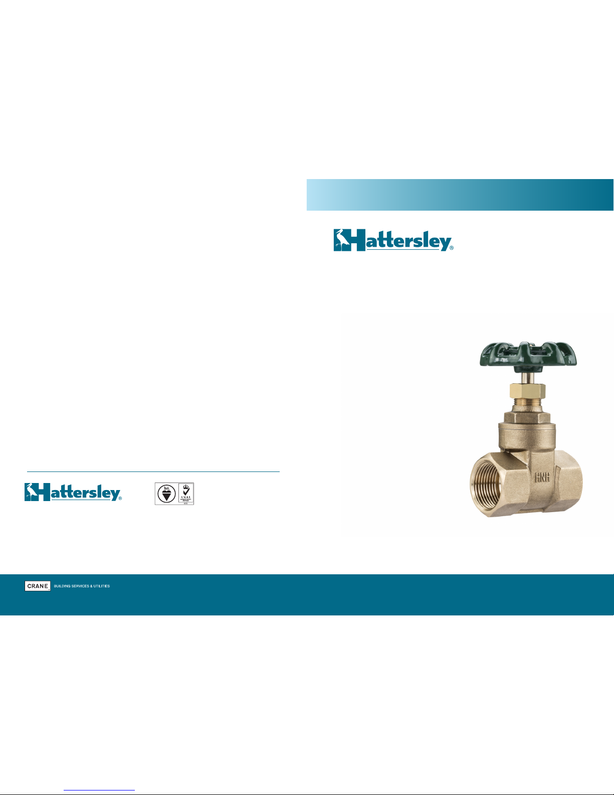
Fig. C31
Bronze Gate Valves
• Gate valves provide complete shut off,
providing the seats remain undamaged,
and offer very little resistance to flow in
the open position. Gate valves are best
suited to infrequent valve operation,
as any dirt in the system can cause
scuffing of the seats. Gate valves are
not recommended for use in the partially
open position because vibration and
erosion of the disc may occur.
• Service temperature and pressure
indicated on the identification plate or
body marking should not be exceeded.
• Hattersley gate valves have not been
designed as fire safe valves.
• Valves must be installed into a well
designed system and it is recommended
that the system be inspected in
accordance with the appropriate
member state legislation.
H_C31_0117
IOM_004B00C31D799
Page 2

Installation and Operating Instructions
Installation
Hatter sley Fig. C31 Bronze Ga te Valves Hatter sley Fig. C31 Bronze Ga te Valves1 2
Fig No. Materials
PED category by valve size
SEP Not CE Marked
C31 Bronze 1/2” - 2”
Preparation
• Ensure valve is suitable for service
conditions e.g. pressure, temperature,
service media.
• Remove dust caps/flange protectors,
where fitted.
• The installation shall be designed to
provide adequate means of draining and
venting to permit cleaning, inspection and
maintenance in the correct manner.
• The product has not been designed to
include corrosion, erosion or abrasion
allowances. Any queries regarding service
applications should be addressed to the
Hattersley - Technical Sales Department.
• The valves have been designed for
loadings, appropriate to their intended use
and other reasonably foreseeable operating
conditions. Loadings caused by traffic,
wind and earthquake have not been taken
into account.
• It is the responsibility of the installer
to ensure that the valves do not exceed
the allowable limits of pressure. However
the equipment is designed to withstand
a momentary pressure surge of up to 10%
above the maximum working pressure.
The piping system shall be so designed
to reduce the risk of fatigue due to
vibration of pipes.
Valve Location
• Valves should be located to ensure ease
and safety of operation and access allowed
for subsequent maintenance of the valve.
• Valves should be located to allow access
for gland adjustment and re-packing.
Piping Supports
These must be carefully aligned and at the
correct distance between centres for the size
and type of pipe. The following publications
provide details of correct spans and
installation details:
BS3974, Specification for Pipe
Supports(Available from BSI)
Threaded Joints
The valves are supplied with taper threads
and, with the use of a thread sealant will give
a pressure tight seal. To avoid distortion of
the valve when fitting and tightening pipe, the
valve must be held securely using the flats
provided at the end of the valve to which the
pipe is being fitted. Care should be taken
to avoid ʻpipe endingʻ. This is a condition
that occurs when the pipe is screwed in too
far resulting in distortion to the valve seat.
The male thread on the pipe must have fully
formed, undamaged threads.
Operation
Bronze Gate valves are designed to seat with
the Hattersley standard hand wheel. Levers,
wrenches or other tools should not generally
be used to operate a valve. Excessive torque
can cause damage to seating faces and/or
stem/handwheel.
Routine Maintenance
• Check for leaks at gland. If gland is leaking
tighten the gland nut(s). The gland nut(s)
should be tightened only enough to prevent
stuffing box leakage. Over-tightening can
cause excessive wear on stem and packing
and make valve difficult to operate. If
leakages still occurring add additional or
new packing.
• Occasionally operate valves that remain
open or closed for long periods to ensure
they are in good working order, thus
avoiding the possibility of being inoperable
in a time of emergency.
General Considerations
• Maximum operating pressure reduces as
service temperature increases. Pressure
and temperature limitations are shown
by the valve body marking or on the
identification plate, and must not be
exceeded.
• Valves are not designed to operate under
high shock loadings. Where pressure
increases occur due to shock loading
(water hammer), they should be added
to the working pressure to obtain the
total pressure acting on the valve. The total
must not exceed the pressure rating of the
valve. A pressure surge, or shock, is usually
caused by the rapid closure of a check
valve or quarter turn valve resulting in a
sudden reduction in flow rate.
• It is bad practice to install valves with the
hand wheels pointing downwards, as
damage may be caused to the gland
packing and stem seal, by debris in
the system.
• Where the handwheel, and therefore
the identification plate, is removed for
maintenance they must be refitted after the
work is completed.
• The surfaces of valves in service may be
subject to extreme temperatures; care
should be taken when handling.
The above products are not suitable for use with unstable fluids.
 Loading...