

Page 1
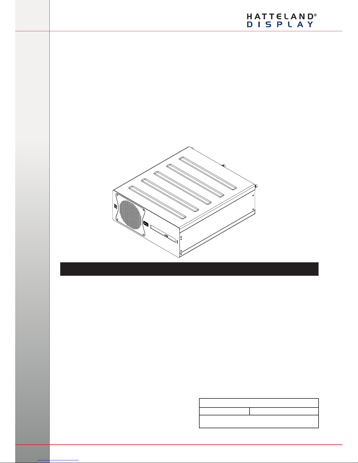
User Manual HT C01
Updated: 20 Jun 2011 Doc Id: INB10042-2 (Rev 14)
Created: 363
Approved: 6987
HT C01 xxy-zzzz
xx = standard or custom
y = operating system
zzzz = conguration dependent
USER MANUAL
HT C01 - Compact Computer
Hatteland Display AS, Åmsosen, N-5578 Nedre Vats, Norway
Tel: (+47) 4814 2200 - [email protected] - www.hatteland-display.com
Please visit www.hatteland-display.com for the latest electronic version of this manual.
Page 2

Copyright © 2011 Hatteland Display AS
Aamsosen, N-5578 Nedre Vats, Norway
Information in this manual is copyrighted to the respective owners. All rights are reserved by
Hatteland Display AS. This information may not, in whole or in part, be copied, photocopied, reproduced,
translated or reduced to any electronic medium or machine-readable form without the prior written consent
of Hatteland Display AS.
The products described, or referenced, herein are copyrighted to the respective owners.
The products may not be copied or duplicated in any way. This documentation contains proprietary
information that is not to be disclosed to persons outside the user’s company without prior written consent
of Hatteland Display AS.
The copyright notice appearing above is included to provide statutory protection in the event of
unauthorized or unintentional public disclosure.
All other product names or trademarks are properties of their respective owners !
WARNING: This is a class A product. In a domestic environment this product may cause radio interference
in which case the user may be required to take adequate measures.
Page 3

3
IND100206-21
INB100042-2 (Rev 14)
Contents
Contents .................................................................................... 3
Contents of package ..........................................................................5
General ...................................................................................... 7
About this manual ...............................................................................8
About Hatteland Display .....................................................................8
hatteland-display.com .........................................................................8
Contact Information ............................................................................ 8
Computers introduction ...................................................................... 9
Basic Construction ..........................................................................10
Product Labels (Examples) .............................................................. 11
Serial Number Label Placement (external) ..................................11
Operating System Serial Number Label Placement (internal) .....12
Installation ............................................................................... 13
Installation and mounting of computers ............................................14
Cables ..............................................................................................14
Conguring DC power input housing connector ...........................14
Ferrites .............................................................................................15
Computer Upgrade Precaution Note ................................................ 16
Cabinet cover removal .....................................................................17
PCI Card removal / replacement - Introduction ................................ 18
PCI Card removal / replacement - Full Lenght & Full Height ...........18
PCI Card removal / replacement - Half Lenght & Full Height ...........19
PCI Card removal / replacement - Half Lenght & Half Height .......... 19
Hard Drive (HDD) removal / replacement ........................................20
DVD/CD Drive removal / replacement ..............................................21
Air Filter removal / replacement - Alternative #1 ..............................22
Air Filter removal / replacement - Alternative #2 ..............................23
Front Fan removal / replacement ..................................................... 24
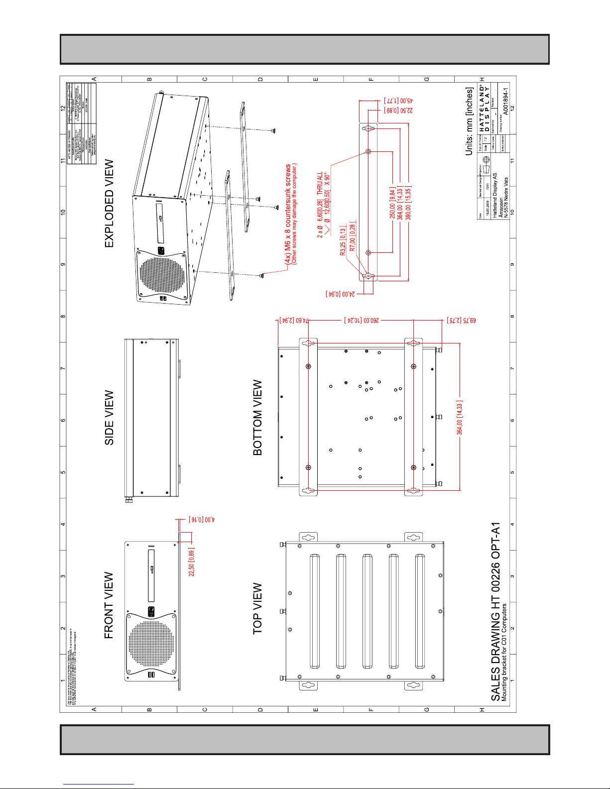
Mounting Brackets for Console Mounting ........................................25
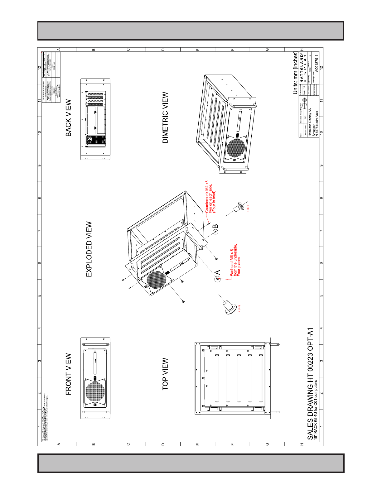
19 inch Rack Kit 4U ..........................................................................26
Sliding Rails ......................................................................................26
Physical Connections ...................................................................... 27
Page 4

Contents
4
IND100206-21
INB100042-2 (Rev 14)
Specications ......................................................................... 31
Specications - HT C01 ....................................................................32
Technical Drawings ................................................................ 33
AC Model .....................................................................................34
DC Model .....................................................................................35
Technical Drawings - Accessories ........................................ 37
Technical Drawings - 19” Rack Kit 4U .............................................. 38
Technical Drawings - Mounting Brackets .........................................40
Appendixes ............................................................................. 41
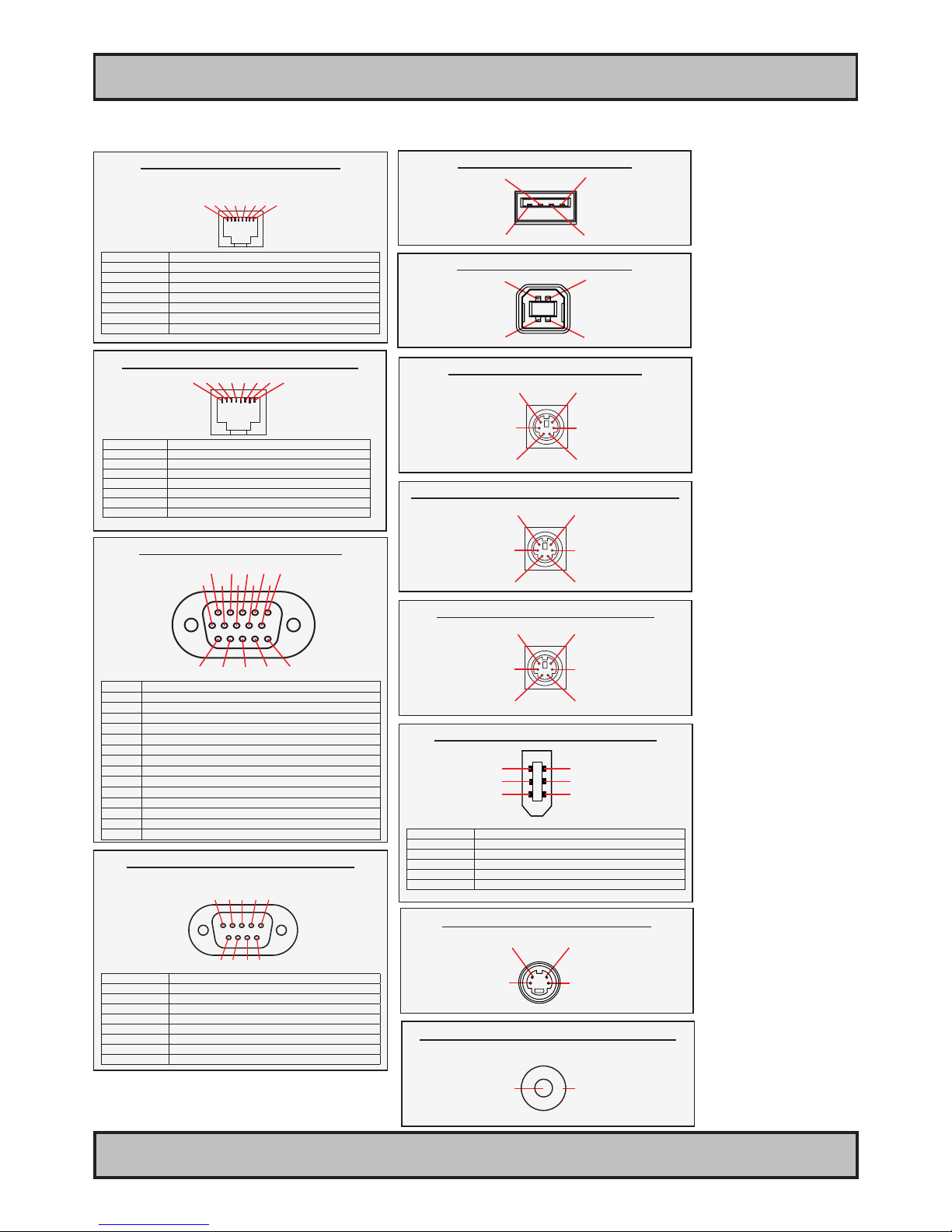
Pin Assignments - Common Connectors ..........................................42
Trouble-shooting ..............................................................................44
Declaration of Conformity .................................................................45
Return Of Goods Information ........................................................... 46
Terms ................................................................................................47
Revision History ...............................................................................50
Page 5
5
IND100207-9
INB100042-2 (Rev 14)
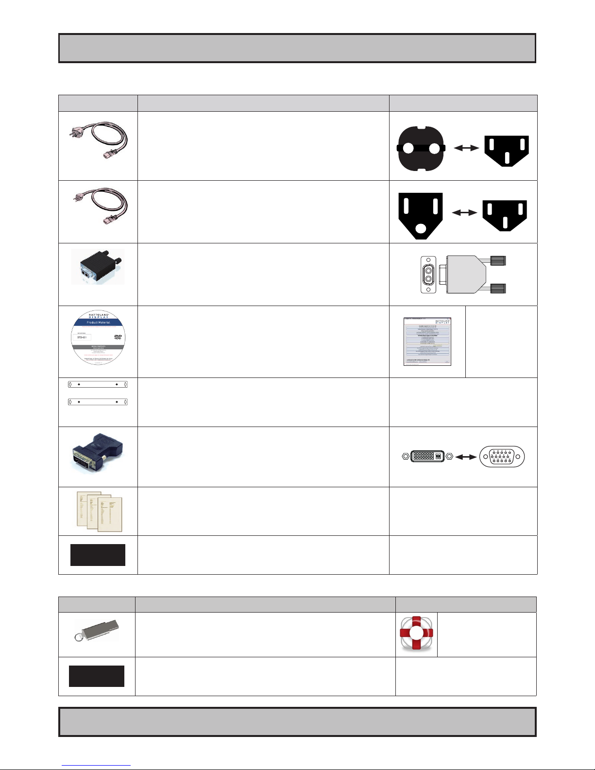
Item Description Illustration
FS-CABLE EU
1 pcs of power cable European Type F “Schuko” to IEC.
Length 1.8m
Note: Only applicable for factory delivered units with AC Power Input
EUR TYPE F
IEC
80099
1 pcs of power cable US Type B plug to IEC.
Length 1.8m
Note: Only applicable for factory delivered units with AC Power Input
US TYPE B
IEC
FCE17-E2W2SS-2N0 &
L17DPPK09JSU (cover)
1 pcs of DC Power Input housing with internal cable screw terminal.
Note: Only applicable for factory delivered units with DC Power Input
MEDIA STD01
1 pcs of Documentation and Driver DVD.
Menu and Driver
browser for
Microsoft® Windows®
HT 00226 OPT-A1
Mounting brackets incl. screws (for console mounting)
DVI-4
1 pcs of DVI-I > RGB/VGA adapter
DVI-I 29P Male to DSUB 15P Female
Test Reports papers:
1 pcs of Product Declaration
1 pcs of Computer Checklist
1 pcs of BurnInTest Certificate
?
For computers that include 3rd party hardware; the package /
accessories box may also include additional CD / HW / Information from
3rd party supplier(s).
This product is shipped with:
Contents of package
Package may also include: (based on accessories/options ordered)
Item Description Illustration
HT 00215 OPT-A1
Recovery Kit (USB Flash)
For reverting back to factory/customized installations.
Note: Only applicable for factory delivered units with HDD/SDD hardware.
Recovery Image (located
on hidden partition on HDD/
SDD)
?
For computers that include 3rd party hardware; the package /
accessories box may also include additional CD / HW / Information from
3rd party supplier(s).
Page 6

6
INB100042-2 (Rev 14)
This page left intentionally blank
Page 7

7
INB100042-2 (Rev 14)
General
Page 8
8
Hatteland Display AS
IND100077-1
INB100042-2 (Rev 14)
General
About this manual
The manual contains electrical, mechanical and input/output signal specications. All specications in this manual,
due to manufacturing, new revisions and approvals, are subject to change without notice. However, the last update
and revision of this manual are shown both on the frontpage and also in the “Revision History” chapter at the end of
the manual.
Furthermore, for third party datasheet and user manuals, please see dedicated Documentation and Driver DVD
delivered with the product or contact our sales/technical/helpdesk personnel for support.
About Hatteland Display
Hatteland Display is the leading technology provider of specialized display and computer products, delivering high
quality, unique and customized solutions to the international maritime, naval and industrial markets.
The company represents innovation and quality to the system integrators world wide. Effective quality assurance and
investment in sophisticated in-house manufacturing methods and facilities enable us to deliver Type Approved and Mil
tested products. Our customer oriented approach, technical knowledge and dedication to R&D, makes us a trusted
and preferred supplier of approved solutions, which are backed up by a strong service network.
hatteland-display.com
You will nd our website full of useful information to help you make an informed choice as to the right product for your
needs. You will nd detailed product descriptions and specications for the entire range on offer be it Series 1, Series
2, Computers & Panel Computers, Military solutions as well as the range of supporting accessories. The site carries
a wealth of information regarding our product testing and approvals in addition to company contact information for our
various ofces around the world, the global service centers and the technical help desk, all ensuring the best possible
support wherever you, or your vessel, may be in the world.
Contact Information
Head ofce, Vats / Norway:
Hatteland Display AS
Åmsosen
N-5578 Nedre Vats, Norway
Tel: +47 4814 2200
Fax: +47 5276 5444
Sales ofce, Frankfurt / Germany:
Hatteland Display GmbH
Werner Heisenberg Strasse 12,
D-63263 Neu-Isenburg, Germany
Tel: +49 6102 370 954
Fax: +49 6102 370 968
Sales ofce, Oslo / Norway:
Solbråveien 20
N-1383 Asker
Norway
Tel: +47 4814 2200
Fax: +47 5276 5444
Sales ofce, Aix-en-Provence / France:
Hatteland Display SAS
31 Parc du Golf, 350,
Avenue JRGG de la Lauzière - CS 90519
13593 Aix-en-Provence Cedex 3, France
Tel: +33 (0)4 42 16 35 15
Fax: +33 (0)4 42 16 35 09
Sales ofce, San Diego / USA:
Hatteland Display Inc.
11440 W. Bernardo Court, Suite 300
San Diego, CA 92127, USA
Tel: +1 858 753 1959
Fax: +1 858 430 2461
For an up-2-date list, please visit www.hatteland-display.com/locations
Page 9
9
Computers
IND101057-2
INB100042-2 (Rev 14)
General
Computers introduction
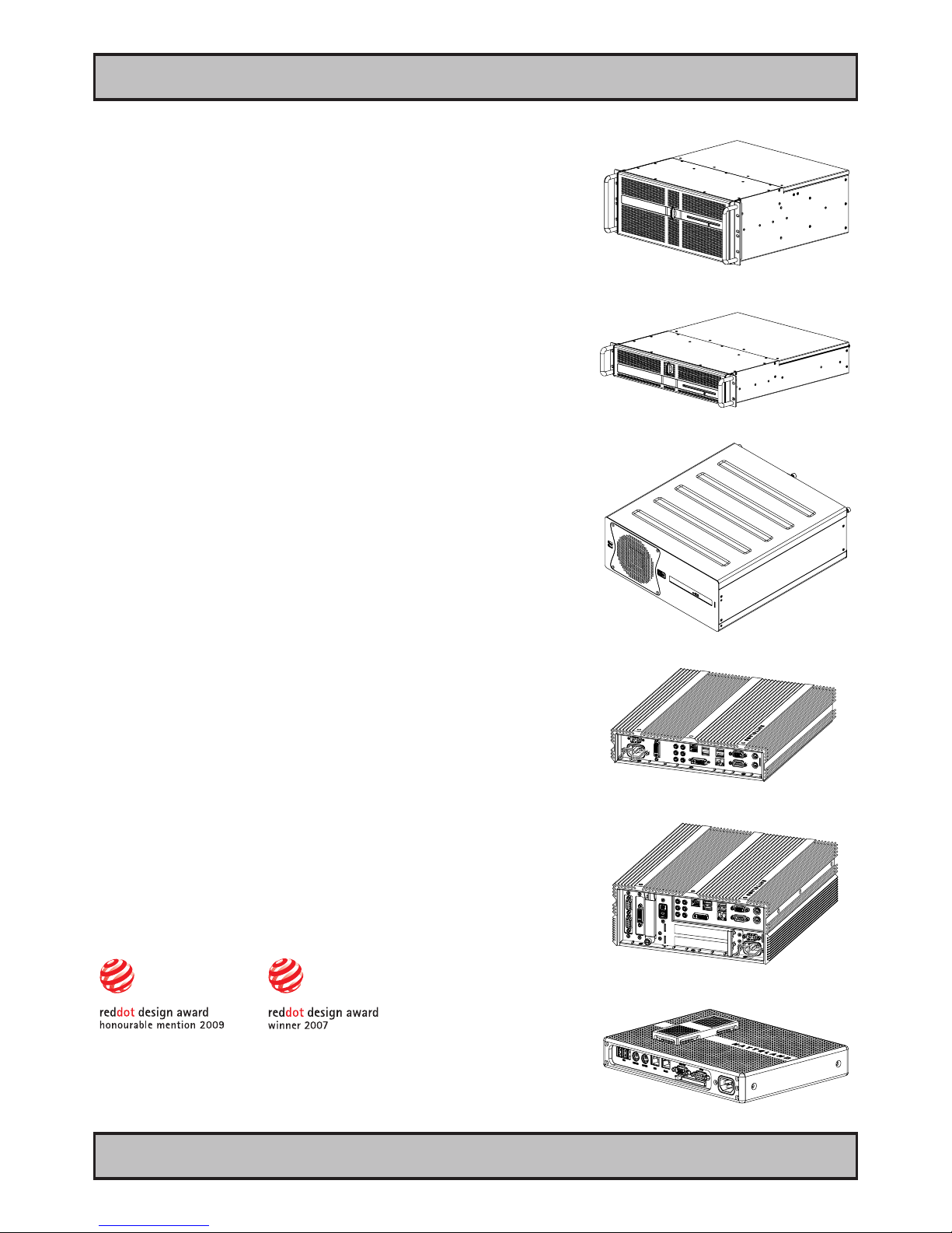
Hatteland Display’s range of type-approved computers is designed to
perform in harsh environments while providing the performance and
flexibility you expect. We offer rack mount and black box/standalone
computer solutions for every need. Our computers are used by system
integrators, boat builders and end-users and can be found on all vessel
types, all over the world.
If you are looking for a high quality computer for navigation, monitoring
or entertainment solutions, Hatteland Display can fulfil your high
expectations at a reasonable cost.
Our computer range covers all eventualities and requirements. We offer
a wide range of processor choices, HDD and power options, and solid
state technology, neatly engineered within industry standard form factors
such as 19” rack mount, 2U, 3U and 4U.
We continually develop our computers portfolio to make the best use of
emerging computer technology so you can be sure that your Hatteland
Display computer offers the power needed to run modern applications,
with the flexibility to be installed wherever you want, for any marine use.
Designed to perform in harsh environments...
Winner of Red Dot awards 2009 / 2007
In 2009 the Hatteland Display HT C01 standalone computer won
a prestigous Red Dot Award with Honourable Mention distinction,
sucessfull detail solution.
The Design Zentrum Nordrhein Westfalen in Germany has been marking
outstanding international product design with its famous and highly
regarded dot since 1955. The Red Dot Product Design Award is an
annual international awards scheme where products from all industries
are chosen for their innovative visual and industrial design.
In 2007 the Hatteland Display Series 2 Display/Panel Computers
range won the Red Dot Award for the overall design and modular
backpack concept, which docks into the screen at the back, comprises
either the typical display connections or a fully equipped panel computer.
Even the computer backpack can operate on its own as a stand-alone
computer.
Page 10
10
IND100077-81
INB100042-2 (Rev 14)
General
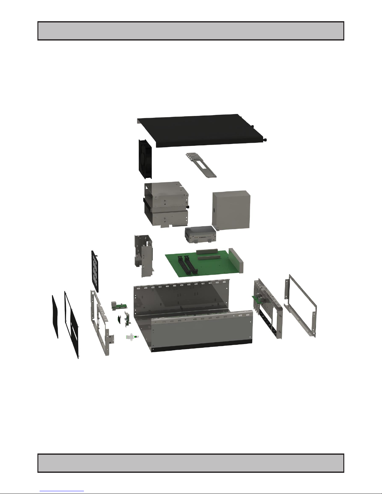
Exploded View
Basic Construction
General illustration
Page 11
11
Product Labels (Examples)
IND100240-5
INB100042-2 (Rev 14)
General
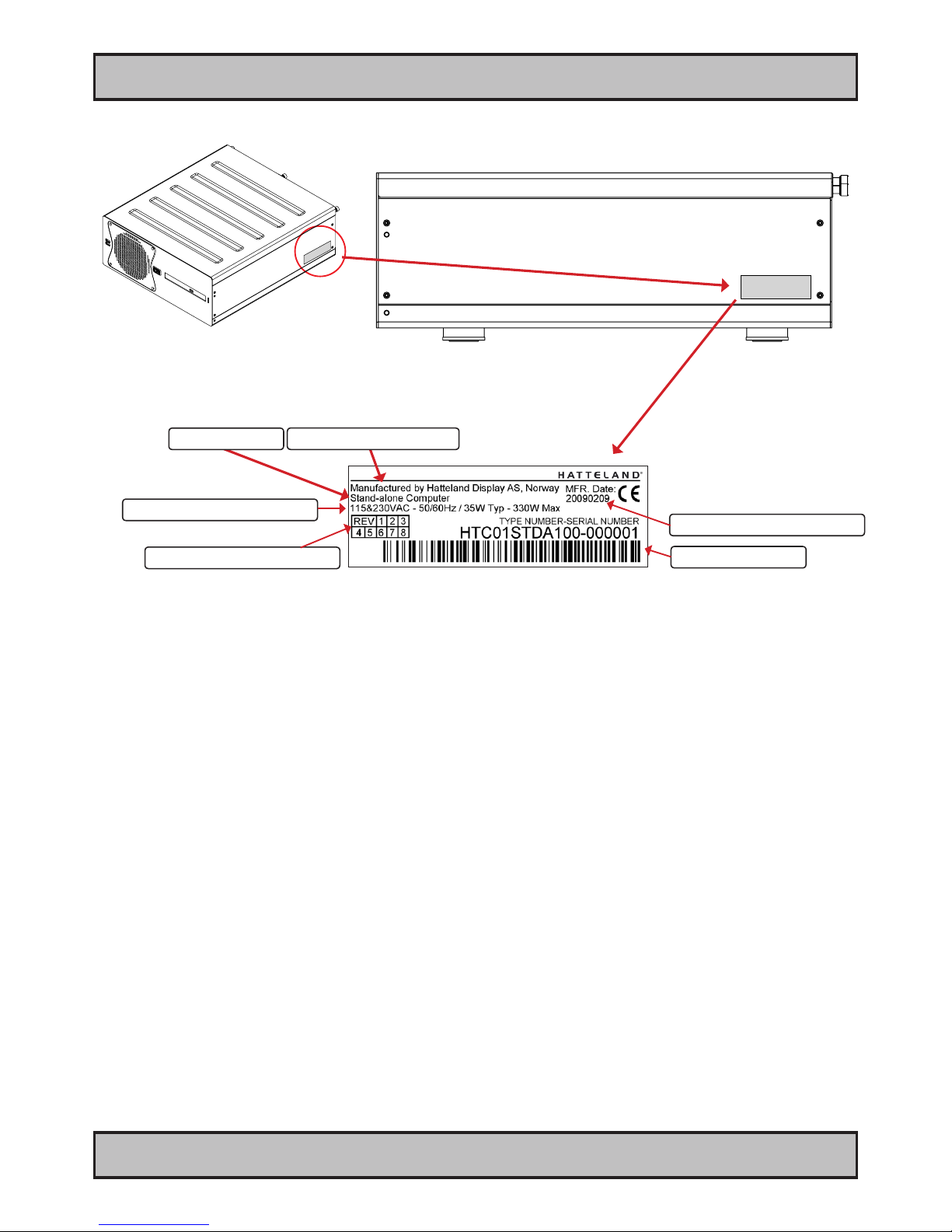
Product Labels (Examples)
Serial Number Label Nomenclature
Serial Number Label Layout
Product Type
Manufacturer & Country
Barcode (TYP+SNO)
Input Voltage & Power Rating
Manufactured Date yyyymmdd
Serial Number Label Placement (external)
Product Hardware Revision
AA XXX AAA-AXXX-XXXXXX NOMENCLATURE - A=Letters, X=Numbers
HT C01 STD-A111-000005 Example
|| ||| ||| |||| ||||||
|| ||| ||| |||| ¤----- Serial Number. Due to revisions, numbers may be 1 to 7 digits
|| ||| ||| |¤¤¤------- Conguration ID (for components like memory, storage etc.)
|| ||| ||| ¤---------- Power Input ID (A=90-264VAC, D=24VDC)
|| ||| ||¤------------ Installed Operating System ID / No Installed OS ID
|| ||| ¤¤------------- Abbreviation for Standard (STD) or reserved customer ID
|| ||¤---------------- Chassis Revision ID
|| |¤----------------- Electronics / Mainboard / Technology Revision ID
|| ¤------------------ Chassis Type ID
|¤-------------------- Maritime Model (HT) or Naval Rugged Model (HM) ID
¤--------------------- Manufacturer ID
Label Size: 6cm x 2cm
Page 12
12
Product Labels (Examples)
IND100240-5
INB100042-2 (Rev 14)
General
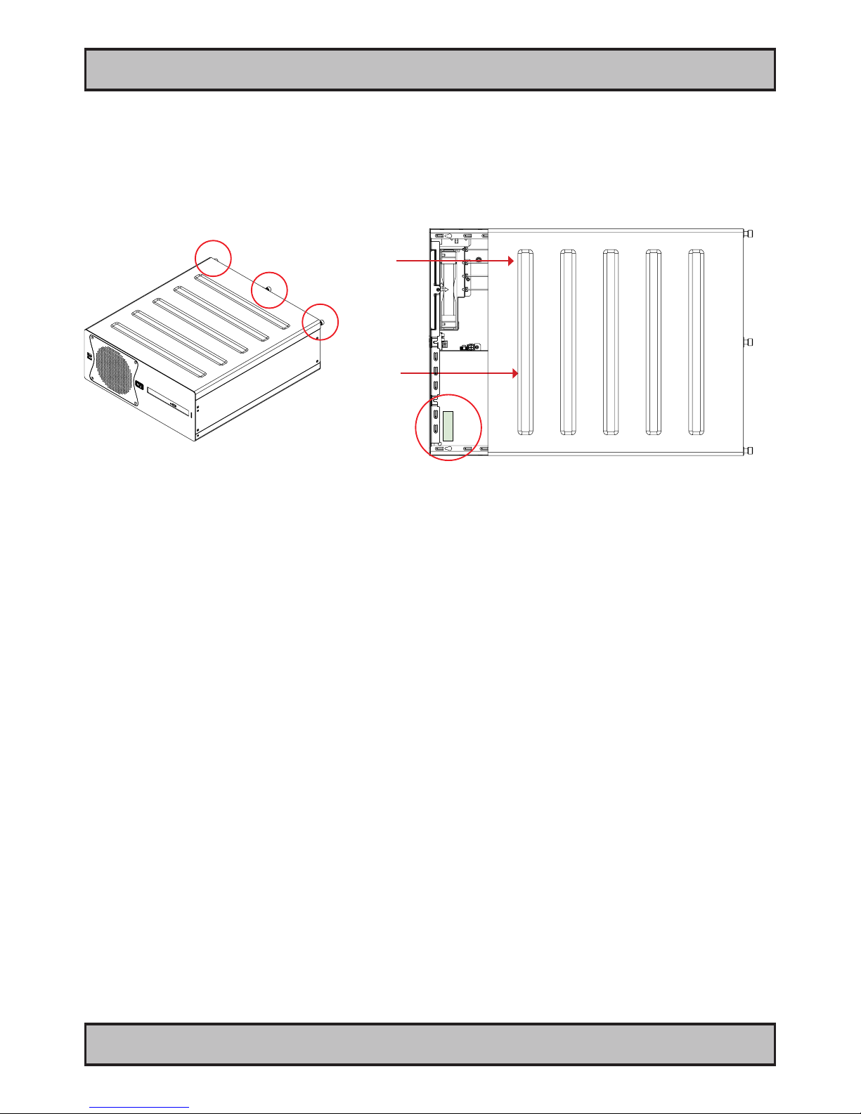
Operating System Serial Number Label Placement (internal)
Please review the “General Installation Recommendations” chapter in this manual before proceeding.
Unscrew the 3 chassis screws (FIG 1), and slide the cover slightly (5mm/0.20”) (FIG 2) and lift the cover to
reveal the label (FIG 3).
FIG1
FIG2
FIG3
Page 13

13
INB100042-2 (Rev 14)
Installation
Page 14
14
IND100210-1
INB100042-2 (Rev 14)
Installation
Installation and mounting of computers
1. Units may be intended for various methods of installation or mounting (rack mounting, panel mounting,
bracket mounting, ceiling/wall mounting); for details, please see the relevant mechanical drawings.
2. Adequate ventilation is a necessary prerequisite for the life of the unit. The air inlet and outlet openings must
denitely be kept clear; coverings which restrict ventilation are not permissible. The product might be without
any ventilation aperatures which means pt.2 does not apply.
3. Exposure to direct sunlight can cause a considerable increase in the temperature of the unit, and might under
certain circumstances lead to overtemperature. This point should already be taken into consideration when
the bridge equipment is being planned (sun shades, distance from the windows, ventilation, etc.)
4. Space necessary for ventilation, for cable inlets, for the operating procedures and for maintenance, must be
provided.
5. To further improve the cooling of the unit we recommend installing Cooling Fans underneath blowing upwards
into the unit air inlet. This may be required in high temperature applications and also when there is reason to
expect temperature problems due to non-optimal way of mounting.
6. For DC powered computer units proper grounding must be achieved by connecting a wire from the unit’s
ground (GND) screw (as indicated on the unit with a icon) to the grounding in your installation setup.
The wire should have a cross sectional area of at least 6mm
2.
The GND screw is located near the
other I/O connectors. Please review the “Physical Overview” chapter for further help.
General mounting instructions
1. The useful life of the components of all Electronics Units generally decreases with increasing ambient
temperature; it is therefore advisable to install such units in air-conditioned rooms. If there are no such
facilities, these rooms must at least be dry, adequately ventilated and kept at a suitable temperature in order
to prevent the formation of condensation inside the unit.
2. With most Electronic Units, cooling takes place via the surface of the casing. The cooling must not be
impaired by partial covering of the unit or by installation of the unit in a conned cabinet.
3. In the area of the wheel house, the distance of each electronics unit from the magnetic standard compass or
the magnetic steering compass must not be less than the permitted magnetic protection distance. This
distance is measured from the centre of the magnetic system of the compass to the nearest point on the
corresponding unit concerned. The exact distance is often mentioned in the specic product specications.
4. Transportation damage, even if apparently insignicant at rst glance, must immediately be examined and be
reported to the freight carrier. The moment of setting-to-work of the equipment is too late, not only for
reporting the damage but also for the supply of replacements.
Cables
Use only high quality shielded signal cables. For RGB/DVI cables use only cables with separate coax for Red, Green
and Blue.
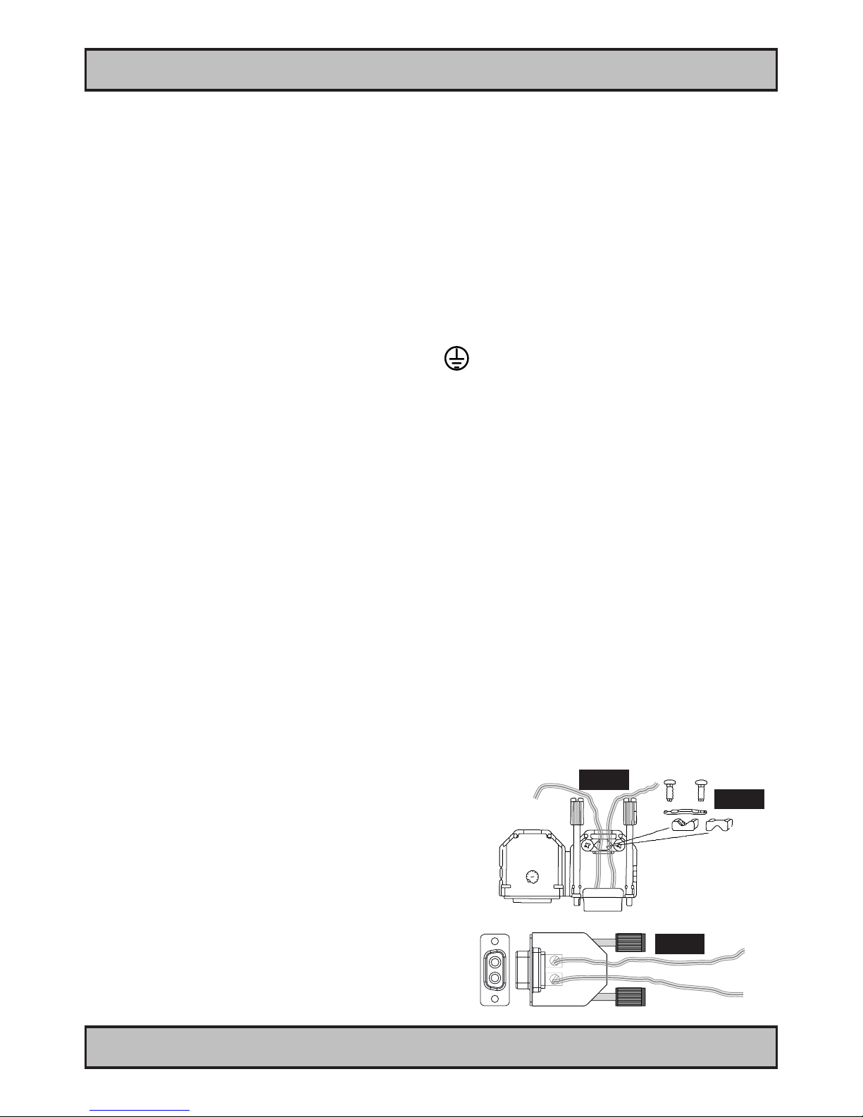
Conguring DC power input housing connector
Note: Only applicable for certain models!
For installations that require DC power input, use the provided
2-pin DC Power Input housing with internal cable screw terminal.
1: Open the housing
2: Unmount the fasteners. (FIG 1)
3: Mount power cables to screw terminal (FIG 2). Note polarity!
4: Secure the cable tightly with fasteners (FIG 3, FIG 1)
5: Close the housing
Note: Please check polarity before connecting any cables
to the screw terminal.
General Installation Recommendations
Screw terminal
FIG 1
FIG 2
FIG 3
+ -
+ -
+
-
Page 15
15
IND100210-1
INB100042-2 (Rev 14)
General Installation Recommendations
Installation
Ferrites
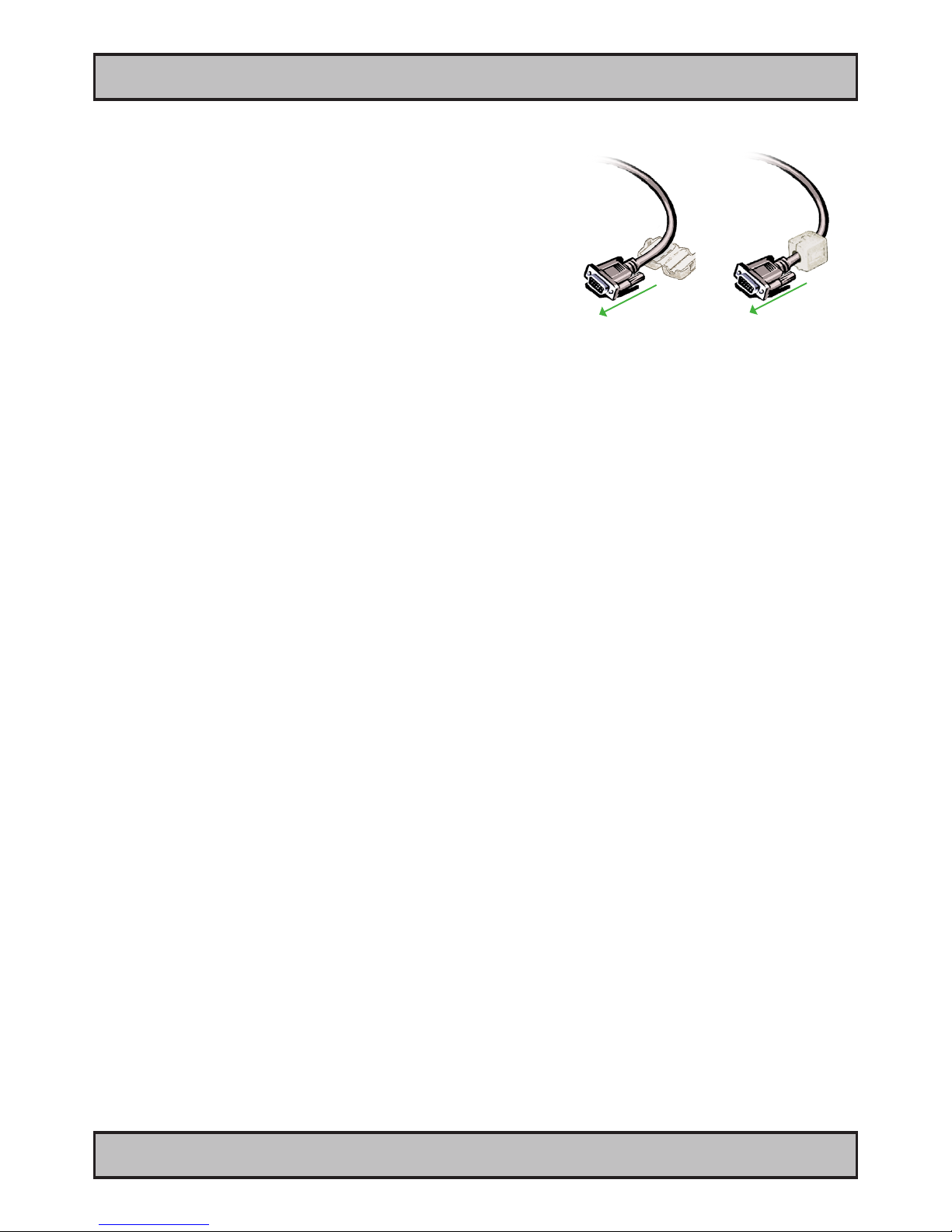
On selected products, the ferrites prevent high frequency
electrical noise (radio frequency interference) from exiting or entering
the equipment. To verify if your product require this, please see the
“Physical Overview” chapter in this manual. The ferrites are part of
the contents of the package also specied in the “Contents Of
Package” chapter early in this manual. The ferrites must be
mounted on specic cables to fully comply with the Type
Approvals!
The ferrites should be mounted (clipped in place on the cable as
shown in illustration) as close as possible to the cable connector
on the rear side of the computer product. Open up the ferrite,
place the cable inside as shown in FIG1, and then gently close it
until a click can be heard (FIG2).
FIG1
To computer
FIG2
To computer
Page 16
16
IND100210-4
INB100042-2 (Rev 14)
General Installation Recommendations
Installation
Computer Upgrade Precaution Note
Users who needs to open the computer to change PCI cards, install more memory, or set internal jumpers can do so
without voiding the warranty. Before opening a unit’s housing to remove or touch a board, proper ESD measurements
must be taken!
1. Operator should ground himself by using a wrist band.
2. The wrist band should be connected to ground via a ground cord.
3. A one megaohm resistor, installed in the wrist connection end of the ground cord, is a safety
requirement.
4. Alternatively an Static-dissipative ESD work mat could be positioned at the workplace.
The 3M™ 8501 Portable Field Service Kit is a good choice for this purpose.
All assisting persons who might come into contact with the endangered boards must also use the ESD equipment.
CAUTION
This unit contains electrostatic sensitive devices.
Observe precautions for handling.
Page 17
17
IND100210-2
INB100042-2 (Rev 14)
General Installation Recommendations
Installation
Cabinet cover removal
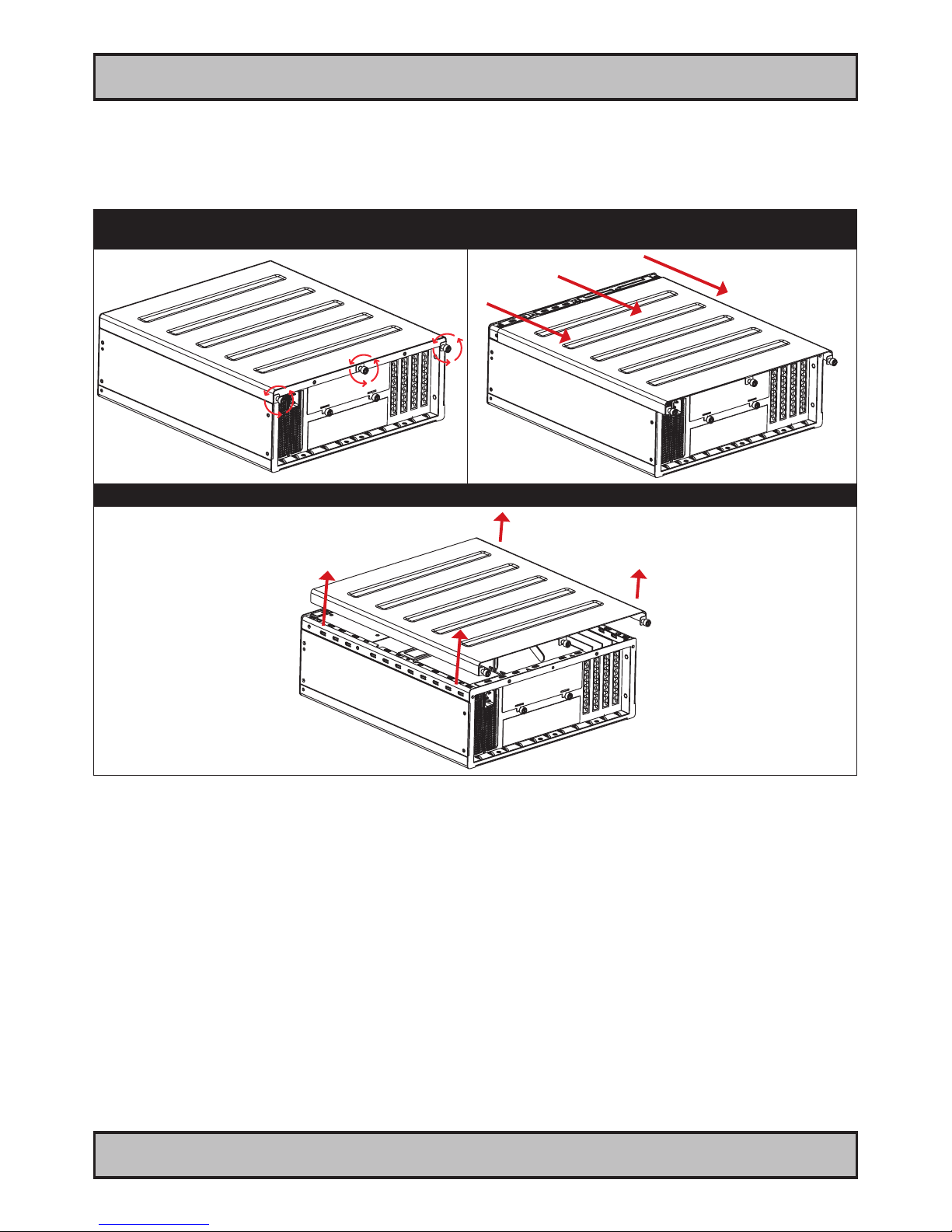
Note: Areas of interest are marked in this section with arrows in RED color. Please disconnect ALL cables from the
computer unit before proceeding!
1: Unscrew 3 screws in rear of cabinet.
Turn anti-clockwise using your ngers.
2: Push cover gently down while pushing forward approx
5mm [0.20”] away from the front and then lift the cover.
3: Lift the cover up with both hands. Repeat the procedure backwards to nalize operation.
Page 18
18
IND100210-2
INB100042-2 (Rev 14)
General Installation Recommendations
Installation
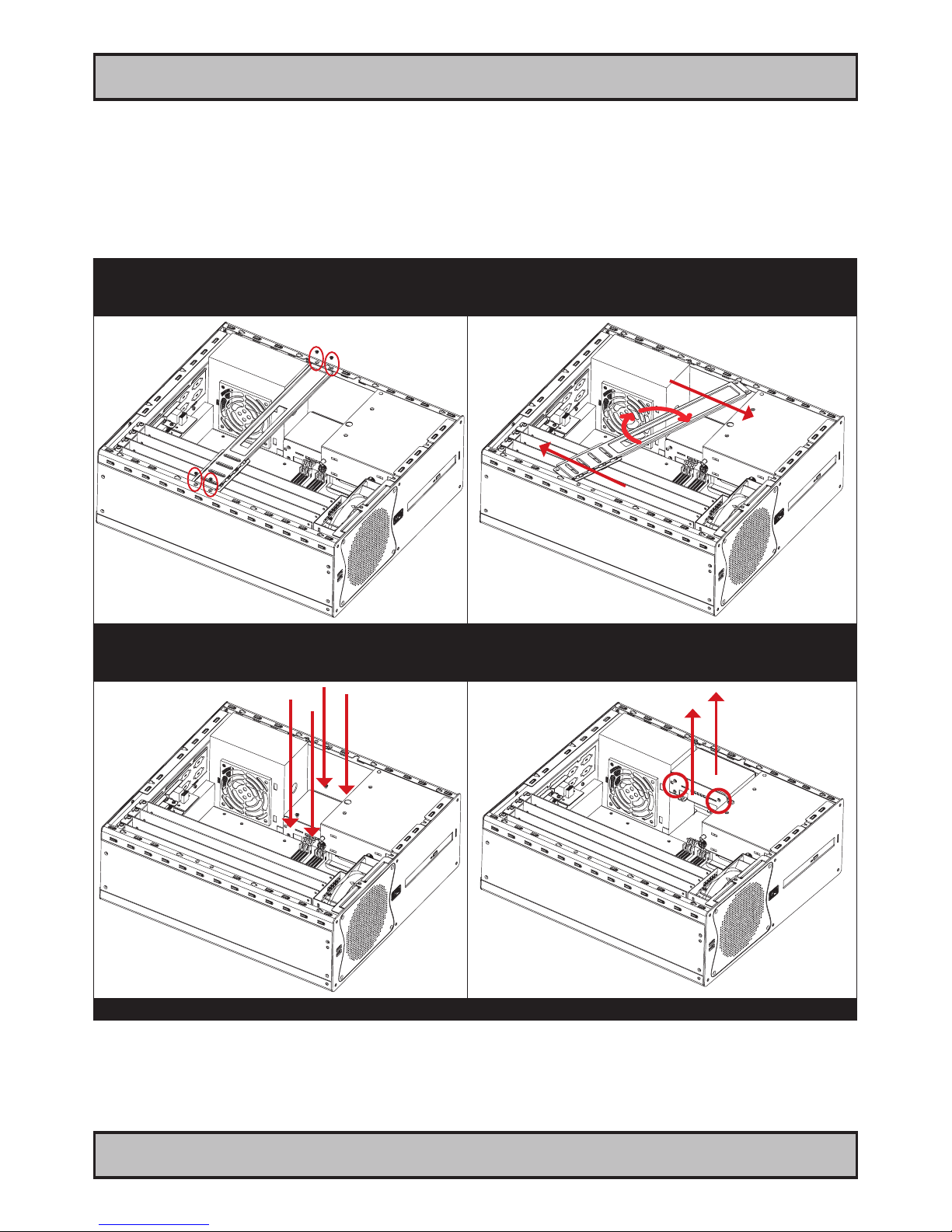
PCI Card removal / replacement - Introduction
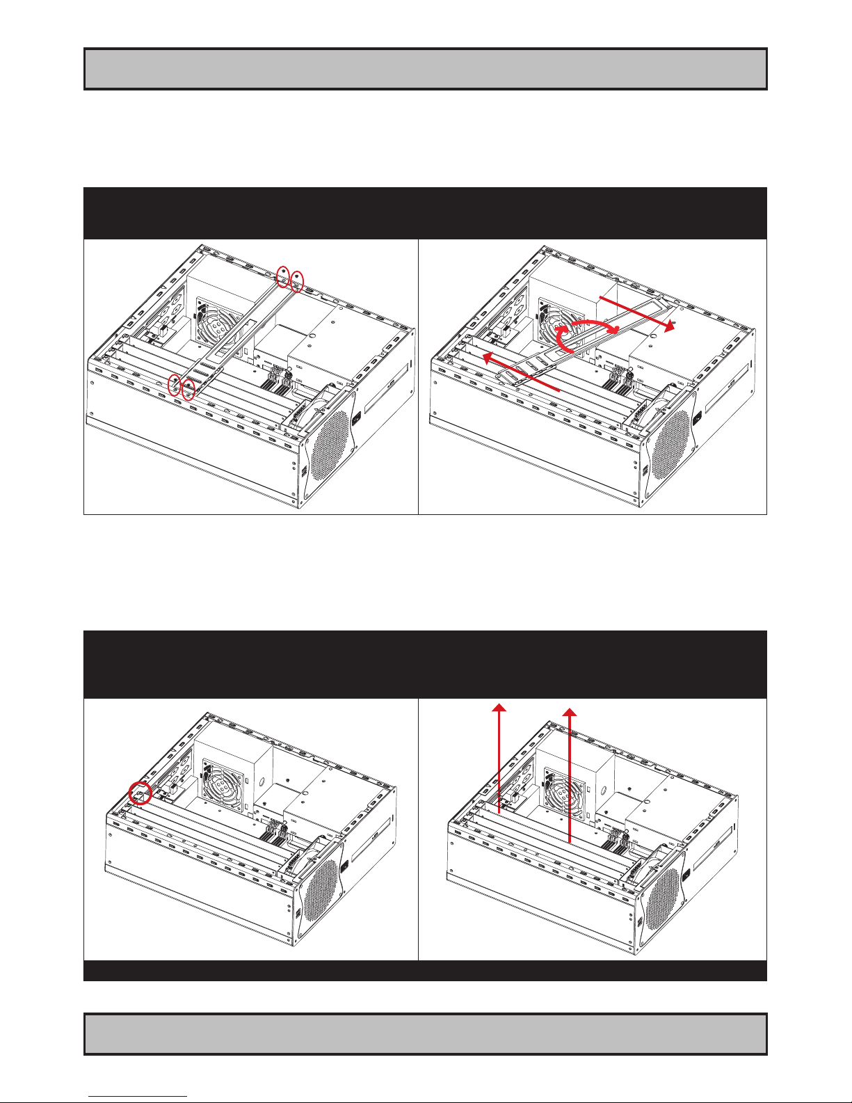
Note: Areas of interest are marked in this section with circles and arrows in RED color. Please disconnect ALL
cables from the computer unit before proceeding!
1: Unscrew 4 screws on each side of the bracket.
Turn anti-clockwise using a Pozidriv #2 screwdriver.
2: Push each side of the bracket, one forward and one
backwards in a 45 degree rotation clockwise to slide it out
of the tracks. Then lift up the the bracket to remove it.
PCI Card removal / replacement - Full Lenght & Full Height
Note: Areas of interest are marked in this section with circles and arrows in RED color. Please disconnect ALL
cables from the computer unit before proceeding!
1: Unscrew 1 screw to loosen the PCI card bracket from
the cabinet. Turn anti-clockwise using a Pozidriv #2
screwdriver.
2: Remove or insert the desired PCI card into the slot.
Make sure you do not force the card down, it should be
mounted with a rm grip with two hands and performed in
a straight up or downwards motion.
Repeat the procedure backwards to nalize operation.
Page 19
19
IND100210-2
INB100042-2 (Rev 14)
General Installation Recommendations
Installation
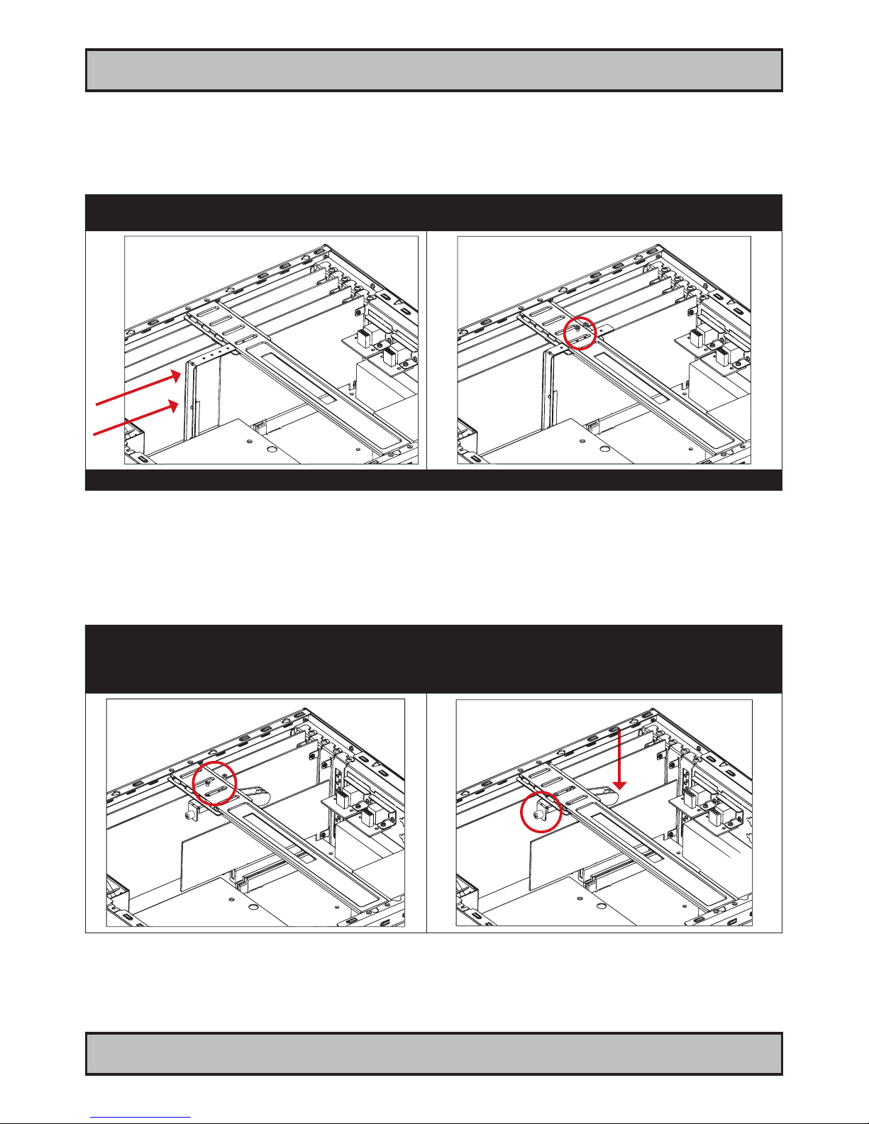
PCI Card removal / replacement - Half Lenght & Full Height
Note: Areas of interest are marked in this section with circles and arrows in RED color. Please disconnect ALL
cables from the computer unit before proceeding!
1: Place the PCI Half Length bracket as shown and
push/slide it in so it reaches the end of the PCI card.
2: Mount 2 screws on top to fasten the PCI Half Length
bracket. Turn clockwise using a Pozidriv #2 screwdriver.
Repeat the procedure backwards to nalize operation.
PCI Card removal / replacement - Half Lenght & Half Height
Note: Areas of interest are marked in this section with circles and arrows in RED color. Please disconnect ALL
cables from the computer unit before proceeding!
1: Place the PCI Half Length/Half Height bracket as
shown and fasten it with 2 screws on the top. Turn
clockwise using a Pozidriv #2 screwdriver.
2: Notice the screw at the end of the bracket. By turning
this clockwise using your ngers the support piece will be
pulled downwards and towards the edge of the PCI card,
thus making it secured. Use a fair amount of force.
Page 20
20
IND100210-2
INB100042-2 (Rev 14)
General Installation Recommendations
Installation
Hard Drive (HDD) removal / replacement
Note: Areas of interest are marked in this section with circles and arrows in RED color. Please disconnect ALL
cables from the computer unit and HDD’s before proceeding!
Note: Illustration shows AC model. For DC models, the power supply must also be removed in order to gain easy access to the HDD. As of June
2011, DC illustration is pending for this page. Meanwhile, please visit http://w ww.hatteland-display.com/support for assistance if needed.
1: Unscrew 4 screws on each side of the PCI bracket.
Turn anti-clockwise using a Pozidriv #2 screwdriver.
2: Push each side of the bracket, one forward and one
backwards in a 45 degree rotation clockwise to slide it out
of the tracks. Then lift up the the bracket to remove it.
3: Unscrew 4 screws on each side holding the HDD
bracket at the bottom of the cabinet.
4: Lift the HDD bracket up and dismount the HDD from
the bracket itself by unscrewing its 4 screws (2 on each
side). Turn anti-clockwise using a Pozidriv #2 screwdriver.
Repeat the procedure backwards to nalize operation.
Page 21
21
IND100210-2
INB100042-2 (Rev 14)
General Installation Recommendations
Installation
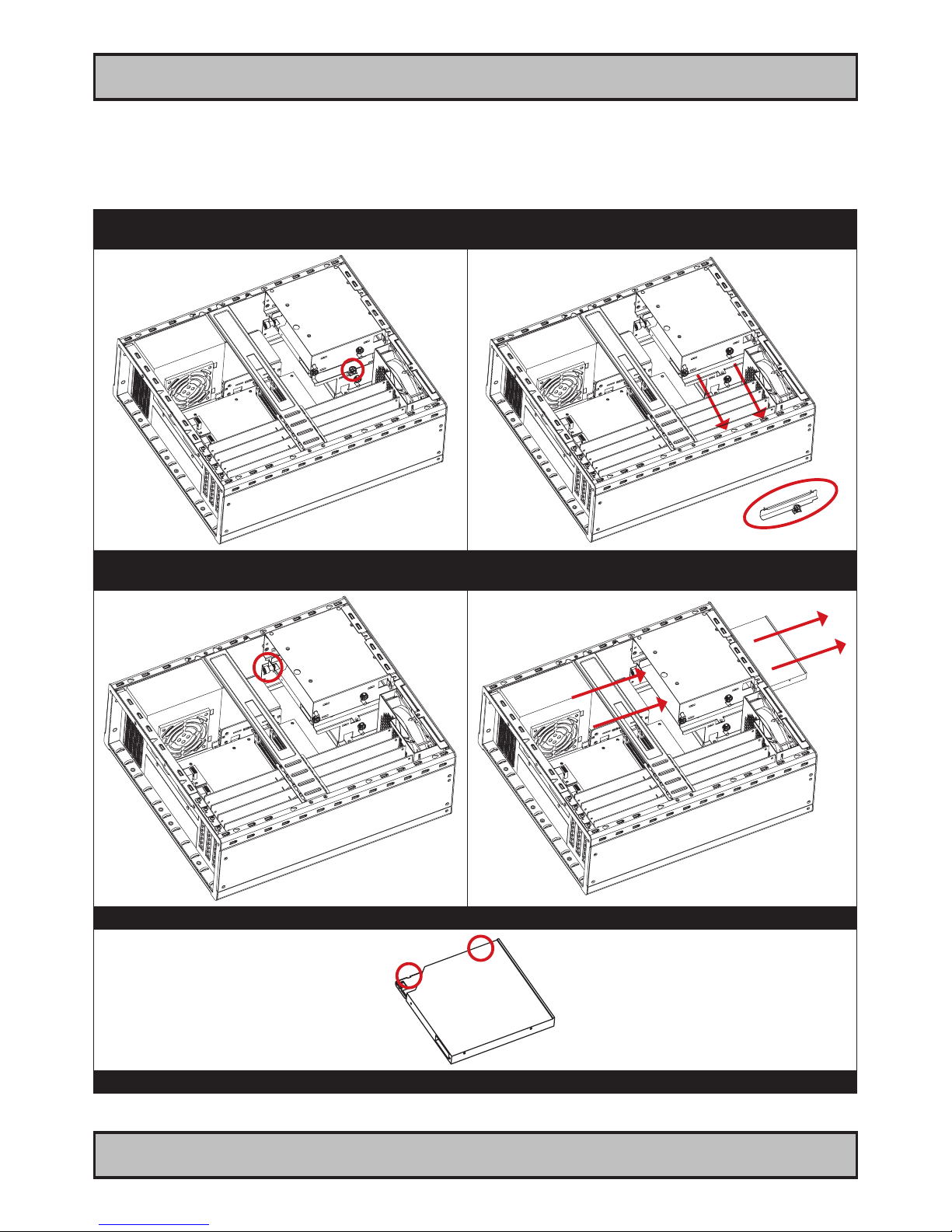
DVD/CD Drive removal / replacement
Note: Areas of interest are marked in this section with circles and arrows in RED color. Please disconnect ALL
cables from the computer unit and DVD/CD drive before proceeding!
1: Unscrew 1 screw on the DVD/CD bracket.
Turn anti-clockwise using your ngers.
2: Gently pull out the DVD/CD bracket away. Remember
it’s orientation and placement.
3: Unscrew 1 screw on the back of the DVD/CD drive.
Turn anti-clockwise using ngers.
4: Gently push with your ngers on the back of the
DVD/CD drive, while using your other hand to pull it out.
5: Unscrew 2 screws on the right side of the DVD/CD drive. Turn anti-clockwise using a Pozidriv #2 screwdriver.
Repeat the procedure backwards to nalize operation.
Page 22
22
IND100210-2
INB100042-2 (Rev 14)
General Installation Recommendations
Installation
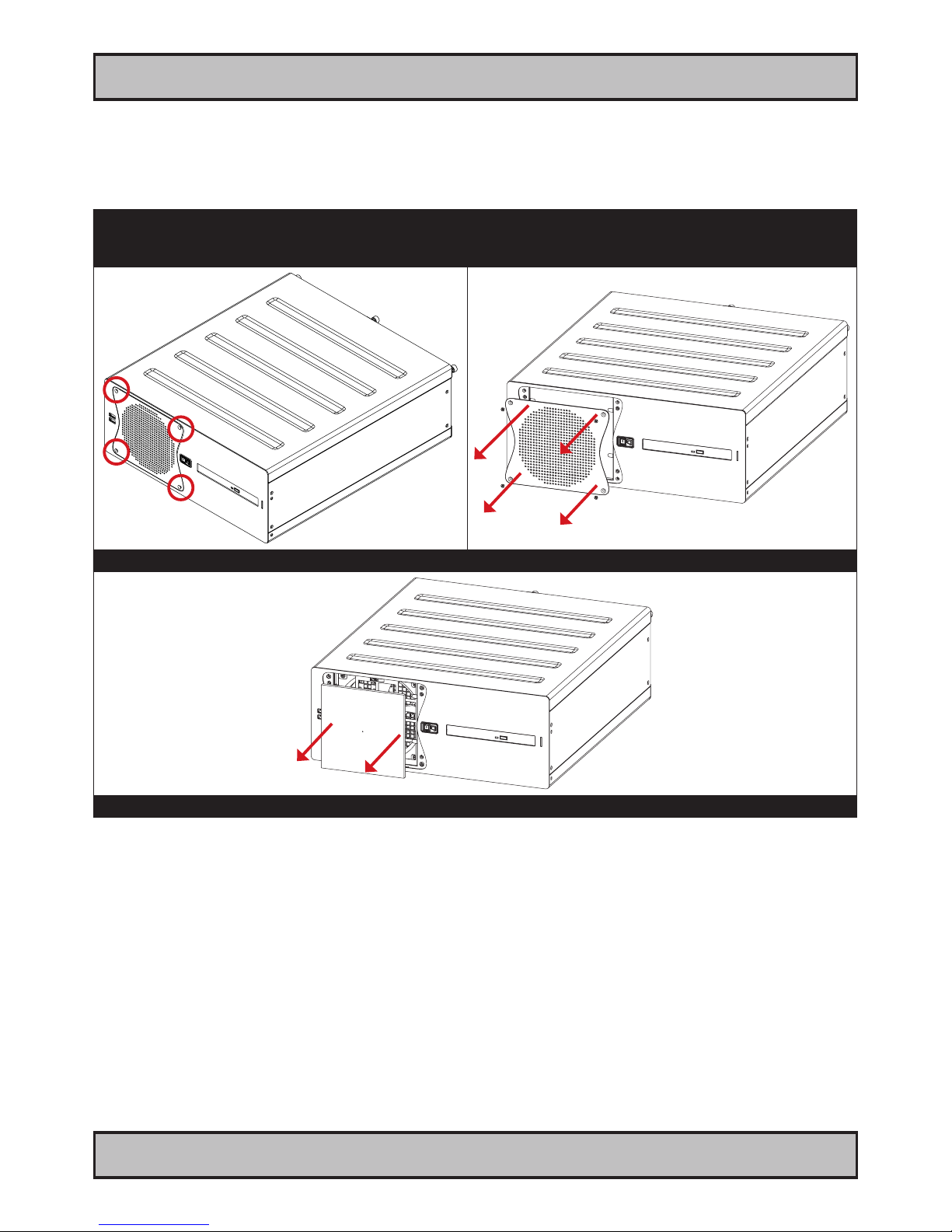
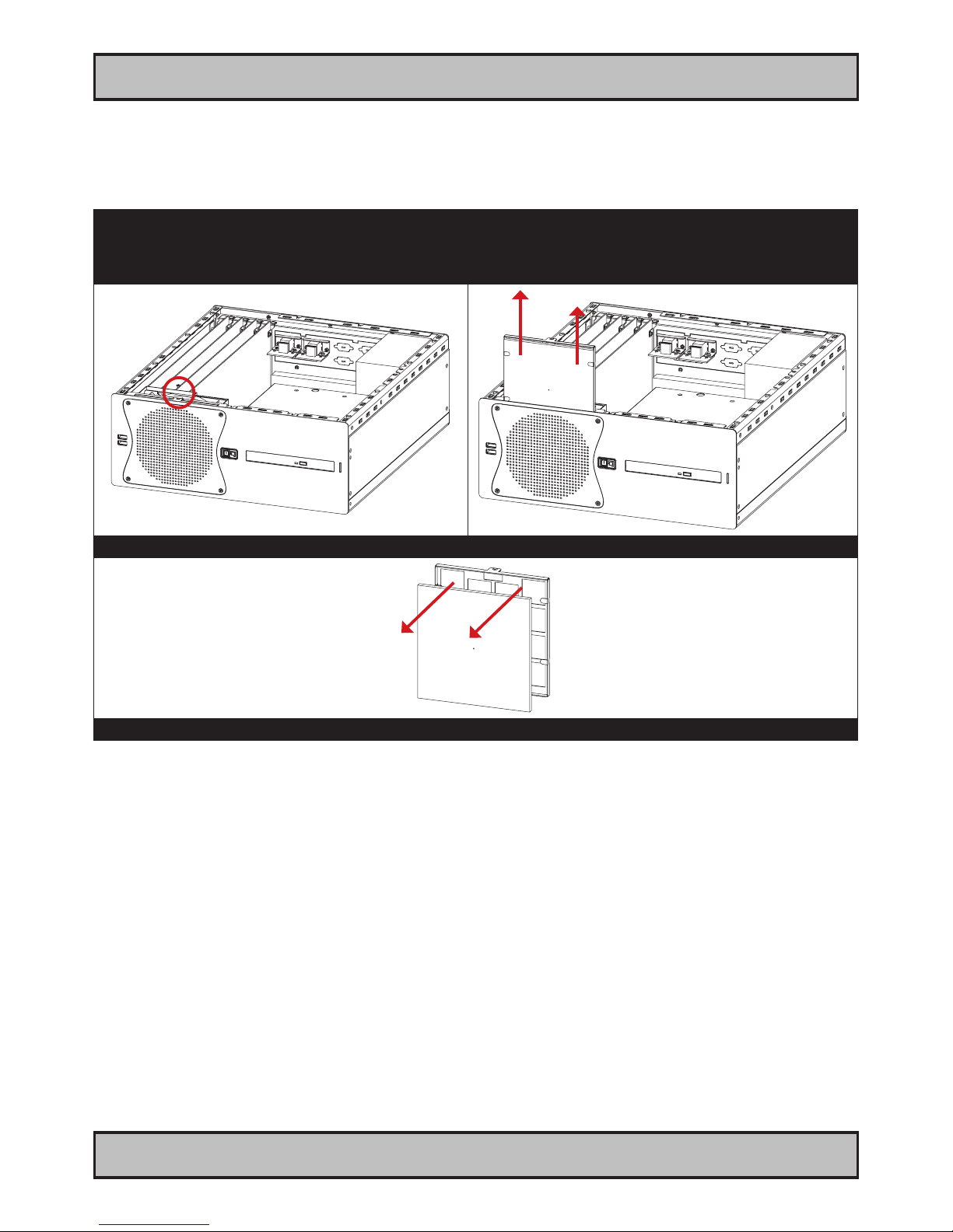
Air Filter removal / replacement - Alternative #1
Note: Areas of interest are marked in this section with circles and arrows in RED color. Please disconnect ALL
cables from the computer unit and cards before proceeding!
1: Unscrew 4 screws from the fan/lter cover in front of
the unit. Turn anti-clockwise using a Pozidriv #2
screwdriver.
2: Gently pull out the fan/lter cover.
3: Gently pull out the Air Filter. Either clean or replace it.
Repeat the procedure backwards to nalize operation.
Page 23
23
IND100210-2
INB100042-2 (Rev 14)
General Installation Recommendations
Installation
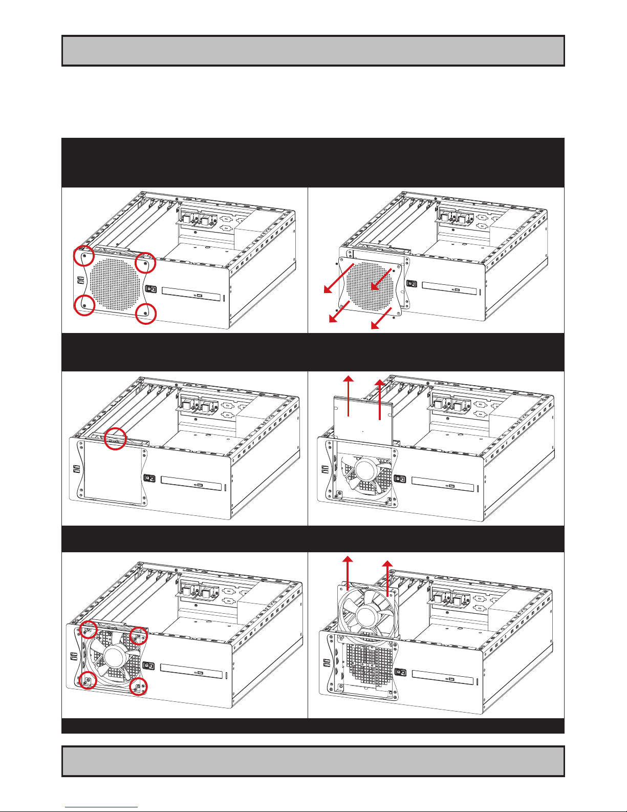
Air Filter removal / replacement - Alternative #2
Note: Areas of interest are marked in this section with circles and arrows in RED color. Please disconnect ALL
cables from the computer unit and cards before proceeding!
1: Remove cabinet cover (see beginning of this
chapter). When cabinet cover is off, unscrew 1 screw
on top which keeps the Air Filter Bracket in place.
Turn anti-clockwise using a Pozidriv #2 screwdriver.
2: Gently pull/slide out the Air Filter Bracket.
3: Gently pull out the Air Filter away from the Air Filter Bracket. Either clean or replace it.
Repeat the procedure backwards to nalize operation.
Page 24
24
IND100210-2
INB100042-2 (Rev 14)
General Installation Recommendations
Installation
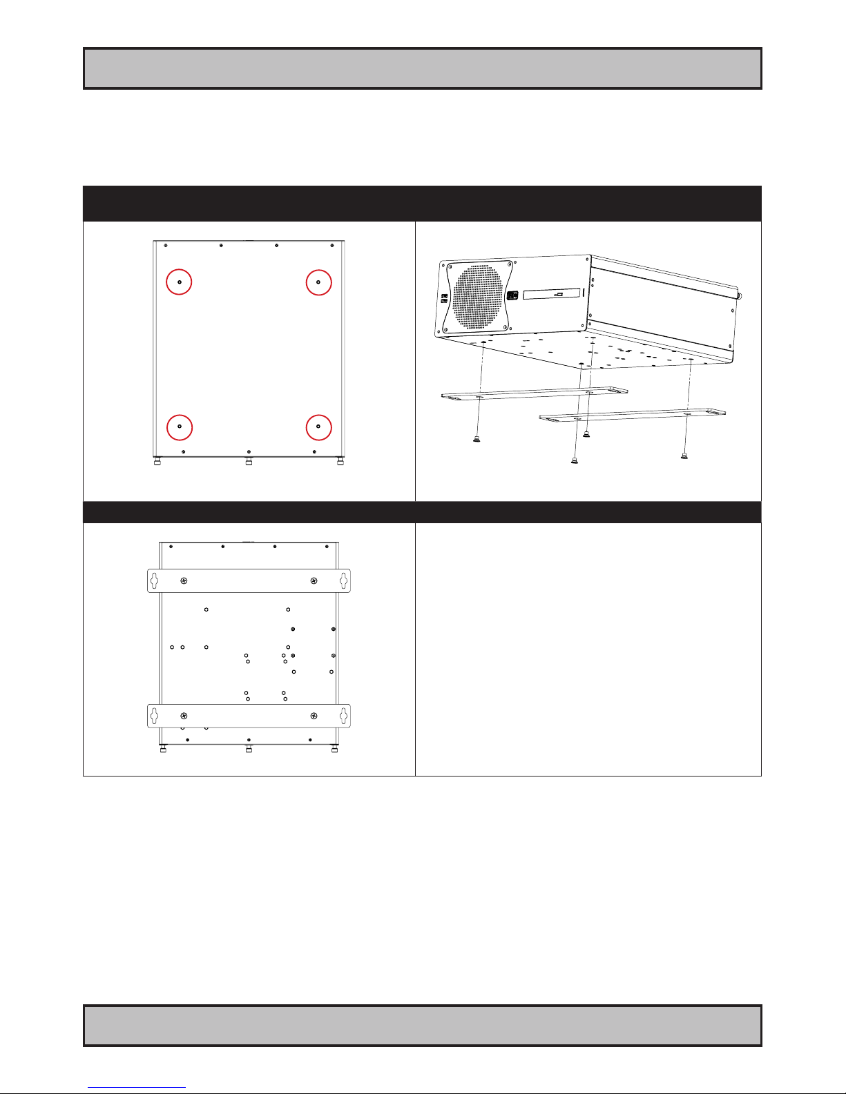
Front Fan removal / replacement
Note: Areas of interest are marked in this section with circles and arrows in RED color. Please disconnect ALL
cables from the computer unit before proceeding!
1: Remove cabinet cover (see beginning of this chapter)
When cabinet cover is off, unscrew 4 screws from the
fan/lter cover in front of the unit. Turn anti-clockwise
using a Pozidriv #2 screwdriver.
2: Gently pull out the fan/lter cover.
3: Unscrew 1 screw on top that keeps the Air Filter
Bracket in place. Turn anti-clockwise using a Pozidriv
#2 screwdriver.
4: Gently pull up the Air Filter Bracket.
5: Unscrew 4 screws that keeps the fan in place.
Turn anti-clockwise using a Pozidriv #2 screwdriver.
6: Lift/slide the fan up from the unit.
Repeat the procedure backwards to nalize operation.
Page 25
25
IND100210-2
INB100042-2 (Rev 14)
General Installation Recommendations
Installation
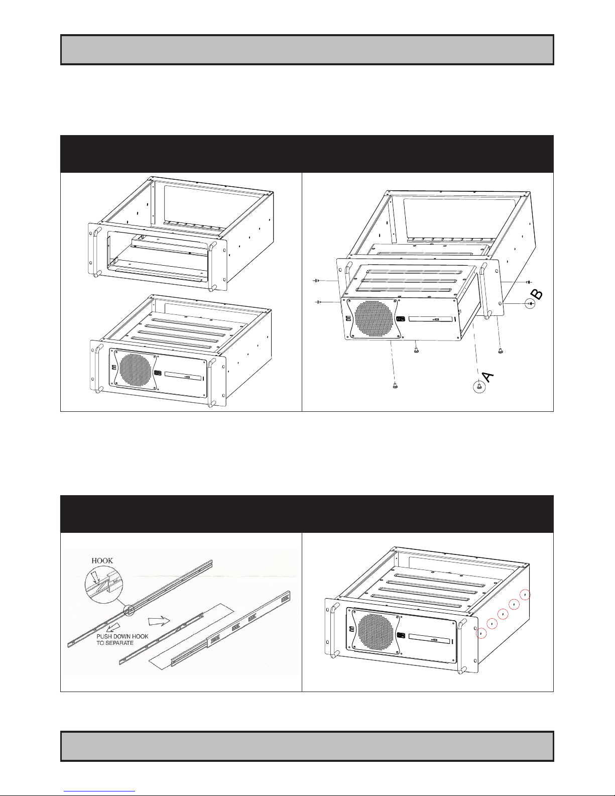
Mounting Brackets for Console Mounting
Note: The unit comes with mounting brackets and screws for console mounting in the package. Please review
specications and “Technical Drawings - Accessories” chapter in this user manual for additional information.
1: Bottom view showing 4 mounting holes. 2: Mount the brackets with 4 x M6x8.
Note: Other/longer screws may damage the computer!
Connector Side
3: Bottom view with mounted brackets.
Page 26
26
IND100210-2
INB100042-2 (Rev 14)
General Installation Recommendations
Installation
19 inch Rack Kit 4U
Note: The unit can also be mounted inside a Hatteland Display 4U cabinet for rack mounting purposes. Please review
specications and “Technical Drawings - Accessories” chapter in this user manual for additional information.
1: Empty 4U cabinet suitable for the computer
and nal solution (note that there is no 4U top cover)
2: Showing mounting and screw (included) positions.
A = 4 Panhead M6 x 8 (mounted from under)
B = 4 Countersunk M4 x8 (4 on each side)
Sliding Rails
Note: The 19 inch Rack Kit 4U can also be mounted with sliding rails 20” or 26”. Please review 3rd party mounting
instructions found in the Sliding Rails package.
1: The 3rd party sliding rails shown below. The 4U
cabinet supports both 20” or 26” sizes depending
on option chosen.
2: Mount the sliding rails on each side of the 4U cabinet.
Fasten it with 5 screws (included) as indicated.
Page 27
27
INB100042-2 (Rev 14)
IND100133-35
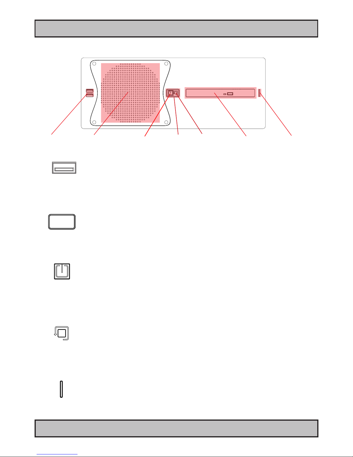
USB1,2 INPUT/OUTPUT:
Supports any USB1.1 (12Mbps) or USB2.0 (480Mbps) compliant peripherals. Drivers for most USB devices are
usually included in operating system or on separate installation CD’s delivered with Third Party products. USB 1.1
devices will operate in USB 1.1 mode (12 Mbps).
POWER LED:
The Power LED Indication ring will illuminate static green when powered on. When power is off and the unit is turned
off, the LED will also off.
Power Button:
To turn ON the computer, press down button and release it immediately. The Power LED indication riing will illuminate
green and the operating system will automatically boot. To turn OFF the computer, press down this button and hold it
for 3 seconds. The operating system may require additionally tasks to be performed before computer shuts down and
turns off the unit.
Reset Button: (Hard Reset)
To reset the computer in case of severe software failure, press this button. This reset button is a hard reset which
means the operating system will NOT be warned. Using this reset method may damage les and / or operating system
in worst case scenarios. Precaution should be taken when using this. To perform a safe software reset, press either
the power button, or use the operating system own reset functionality if possible.
HDD LED:
The Power LED Indication will illuminate green when HDD is reading/writing. When there is no HDD activity the LED
will be off.
Front area of computer
USB 1,2 12cm FAN intake+lter
Reset ButtonPower Button
Physical Connections
DVD/CD Drive
Power LED
HDD LED
Page 28
28
INB100042-2 (Rev 14)
IND100133-35
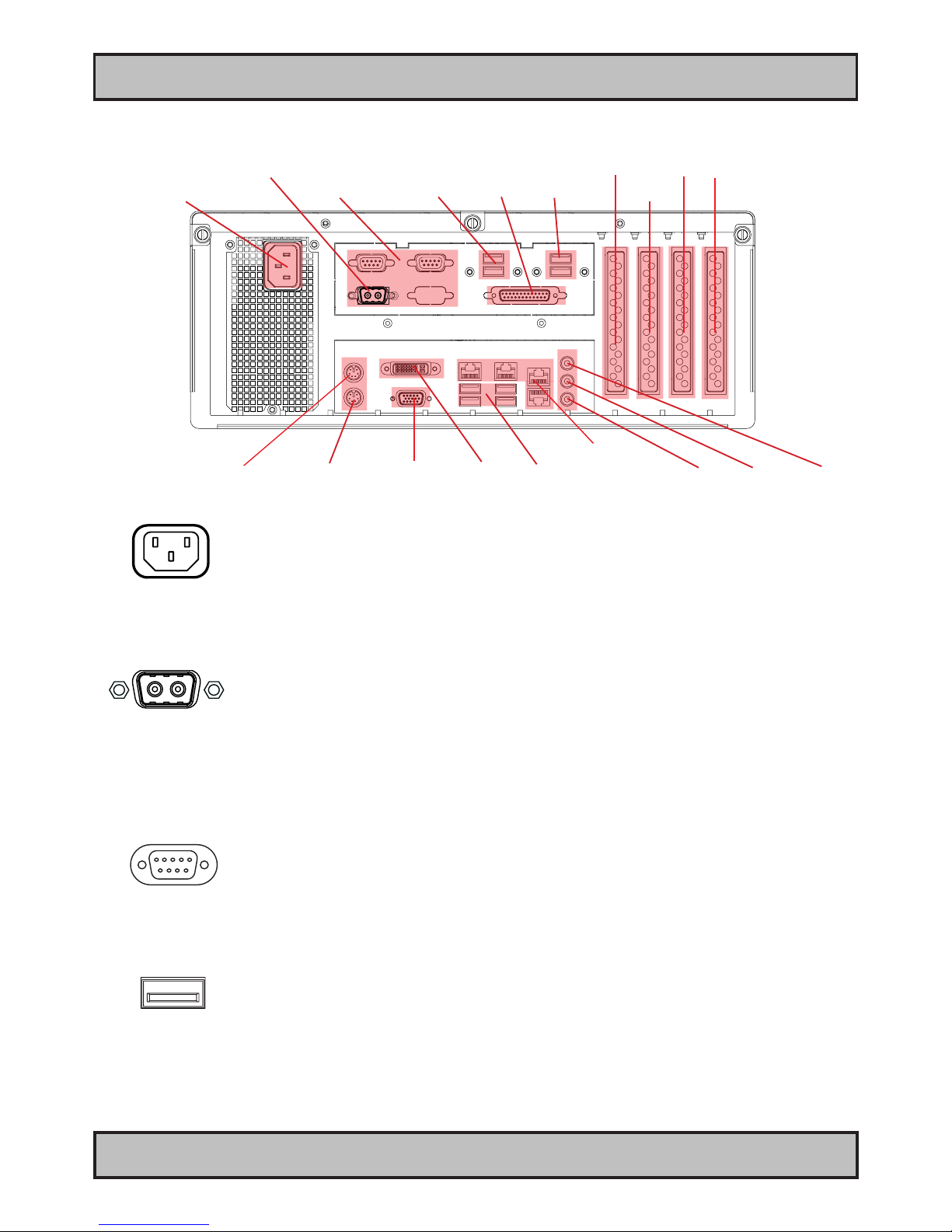
Power INPUT: (For units supporting AC input)
The internal AC power module supports both 115VAC/60Hz and 230/50Hz power input using a standard IEC
European power plug. See specications for more information.
+ -
POWER INPUT: (For units supporting DC input)
Connect your DC power cable to the 2P Amphenol FCC17 D-SUB Connector (male). Secure the cable to the hex
spacers provided on the unit, and secure the other end to your power supply. The internal DC power module supports
24VDC. Please check specifications for your unit.
COM1,2 Serial Port INPUT/OUTPUT:
Supports RS-232 using D-SUB 9P Male connectors. Fasten the cable to the connector using the provided screws on
the cable housing itself.
USB7,8 and USB9,10 INPUT/OUTPUT:
Supports any USB1.1 (12Mbps) or USB2.0 (480Mbps) compliant peripherals. Drivers for most USB devices are
usually included in operating system or on separate installation CD’s delivered with Third Party products. USB 1.1
devices will operate in USB 1.1 mode (12 Mbps).
Connector area of computer
Physical Connections
Power Input AC
Mouse PortKeyboard Port
COM1,2
Network GBLAN
USB 3,4,5,6 Mic In, Line Out, Audio Line In
USB 7,8
DVI-I
PCIe X16 (add2)
LPT
USB 9,10
VGA RGB
PCI
PCI
PCIe X1
Power Input DC
Page 29
Physical Connections
29
INB100042-2 (Rev 14)
IND100133-35
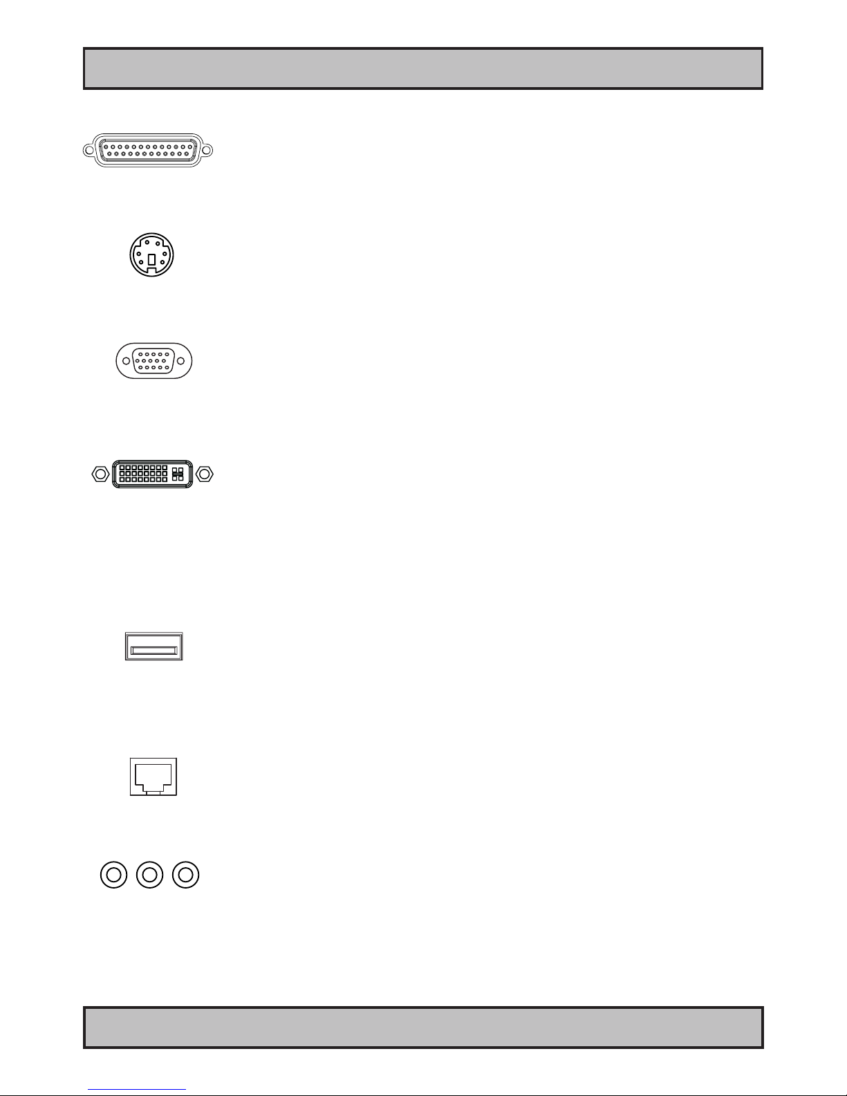
LPT1 Parallel Port INPUT/OUTPUT:
Standard LPT1 Printer/Parallel (SPP/EPP/ECP) port using a D-SUB 25P Female connector. Fasten the cable to the
connector using the provided screws on the cable housing itself.
PS/2 Mouse and PS/2 Keyboard INPUTS:
Connect the PS/2 mouse cable to the PS/2 5P Connector (female) marked with MS. Connect the PS/2 keyboard cable
to the PS/2 5P Connector (female) marked with KB.
RGB OUTPUT:
Will output a signal from the computer for use with external display or monitor. Connects via a High Density D-SUB
15P Female connector. Fasten the cable to the connector using the provided screws on the cable housing itself.
DVI-I OUT:
Connect your DVI cables to the DVI-I 24P Connectors (female) on the rear side of the unit. If possible, screw the DVI
cables to the connectors and make sure you don’t bend any of the pins inside the DVI cable connector.
Note: The DVI-I OUT connector can be congured as RGB OUT with the provided DVI-4 adapter. However, the signal
outputted is a direct clone of RGB OUT signal. For true independent output, please connect a RGB cable to RGB OUT
and a DVI cable to DVI-I OUT (without DVI-4 adapter) to achieve two different desktop outputs to two different
displays or monitors.
USB3,4,5,6 INPUT/OUTPUT:
Supports any USB1.1 (12Mbps) or USB2.0 (480Mbps) compliant peripherals. Drivers for most USB devices are
usually included in operating system or on separate installation CD’s delivered with Third Party products. USB 1.1
devices will operate in USB 1.1 mode (12 Mbps).
Network INPUT/OUTPUT:
Supports 10/100/1000Mbps Ethernet (LAN). Suitable for twisted pair cables CAT.5E. Make sure the network cable
connector ”clicks” into the RJ-45 connector.
Audio INPUT/OUTPUT:
All connectors are 3.5” Jack Stereo. AC’97 audio support. Either function as Stereo Line In, Stereo Line Out and
Stereo MIC In or as 6-channel surround out where conguration is as follows:
Line In - Rear Sound L/R
Line Out - Front Sound L/R
Mic In - Center/Subwoofer Sound.
These settings can be modied within the audio driver software.
Page 30
Physical Connections
30
INB100042-2 (Rev 14)
IND100133-35
PCIe X16 (add2) Slot:
Supports Full Height and Full Length Prole card in one available slot. Cards is normally installed from factory. Please
review the General Installation Recommendations chapter in this manual for more information. Additionally consult the
3rd party manual available on the attached documentation CD delivered with this unit.
PCIe X1 Slot:
Supports Full Height and Full Length Prole card in one available slot. Cards is normally installed from factory. Please
review the General Installation Recommendations chapter in this manual for more information. Additionally consult the
3rd party manual available on the attached documentation CD delivered with this unit.
PCI Rev2.3 Slots:
Supports Full Height and Full Length Prole card in two available slots. Cards is normally installed from factory. Please
review the General Installation Recommendations chapter in this manual for more information. Additionally consult the
3rd party manual available on the attached documentation CD delivered with this unit.
Page 31

31
INB100042-2 (Rev 14)
Specications
Page 32
32
INB100042-2 (Rev 14)
IND100129-106
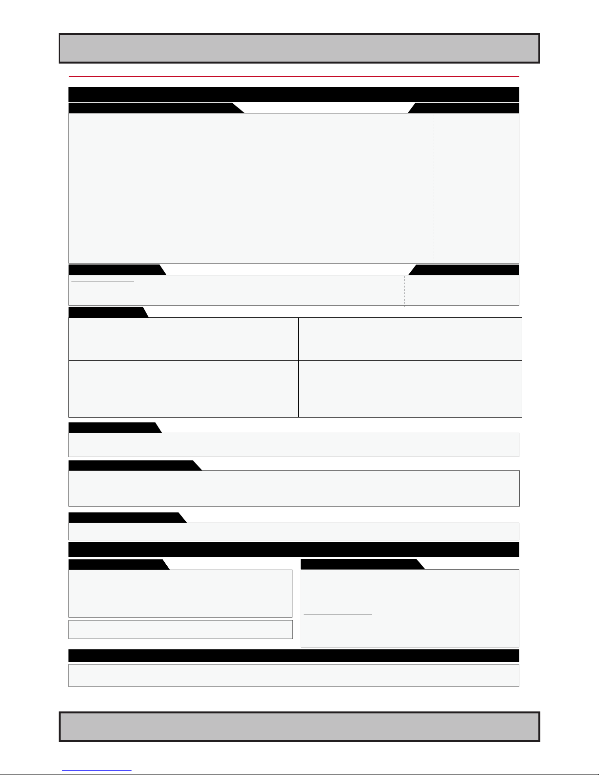
Specications - HT C01
Note: All specifications are subject to change without prior notice!
PRODUCT SPECIFICATIONS - HT C01 STx-xxxx
These products have been tested / type approved by the following classification societies: (1=AC, 2=DC).
IEC 60945 4th (EN 60945:2002) (1) IACS E10 (1) EN61162 (1) ClassNK - Nippon Kaiji Kyokai (1) DNV - Det Norske Veritas (1)
LRS - Lloyd’s Register of Shipping (1) GL - Germanischer Lloyd (1,2) BV - Bureau Veritas (1,2) ABS - American Bureau of Shipping (1,2)
• 345 (W) x 133 (H) x 390 (D) mm
• 13.58" (W) x 5.24" (H) x 15.35" (D)
• Weight: 10 kg (approx)
• Power button, power led, reset button and HDD Led in front.
• Replaceable Air Filter in front
• Includes Mounting Brackets (for console mounting)
Compass Safe Distance HT C01 STx-xxxx = Standard: 155cm/Steering: 95cm
MTBF (Mean Time Between Failures) = 22581 hours
Power Supply Options:
• 115&230VAC - 50/60Hz : Model HT C01 STx-Axxx (330W) STD IEC
• 24 VDC : Model HT C01 STx-Dxxx (220W) 1 x 2p D-SUB (male) Amphenol FCC17
• Power Consumption - Operating : 70W typical (HT C01 STx-A100) - 70W typical (HT C01 STx-D100)
• Operating : Temperature -15 deg. C to +55 deg. C
Humidity up to 95%
DNV Temperature Class B +70 deg. C for 2 hours
• Storage : Temperature -20 deg. C to +60 deg. C
Humidity up to 95%
HT C01 STD-A100 or -D100 with:
1 x Intel® Core™2 Duo Desktop Processor E8400 - 3.0GHz
2 x 1GB installed (Dual Channel DDR2 800/667 SDRAM, 240-pin DIMM)
1 x Easy Replaceable Automotive HDD 250GB or more* 2.5" SATA, 5400RPM, 8MB Buffer
1 x Microsoft® Windows® Embedded Enterprise (XP Professional Eng w/SP2c, 32bit)
HT C01 STD-A101 or -D101 with:
1 x Intel® Core™2 Duo Desktop Processor E8400 - 3.0GHz
2 x 1GB installed (Dual Channel DDR2 800/667 SDRAM, 240-pin DIMM)
1 x Easy Replaceable Automotive HDD 250GB or more* 2.5" SATA, 5400RPM, 8MB Buffer
1 x Bluestorm Serial I/O card (4 x COM Ports - Supports RS-232/422/485)
1 x Microsoft® Windows® Embedded Enterprise (XP Professional Eng w/SP2c, 32bit)
HT C01 STD-A102 or -D102 with:
1 x Intel® Core™2 Duo Desktop Processor E8400 - 3.0GHz
2 x 1GB installed (Dual Channel DDR2 800/667 SDRAM, 240-pin DIMM)
1 x Easy Replaceable Automotive HDD 250GB or more* 2.5" SATA, 5400 RPM, 8MB Buffer
1 x Microsoft® Windows® Embedded Enterprise (XP Professional Eng w/SP2c, 32bit)
1 x Matrox® P690 Dual Head Graphics Card, PCIe, DVI-I, 128MB, Max 2048 x 1536*
* If 1600x1200 resolution is used, DVI signals must be set to CVT-RB (Coordinated Video
Timing-Reduced Blanking) mode manually.
HT C01 STD-A104 or -D104 with:
1 x Intel® Core™2 Duo Desktop Processor E8400 - 3.0GHz
2 x 1GB installed (Dual Channel DDR2 800/667 SDRAM, 240-pin DIMM)
1 x 30GB or more* 2.5" SATA Solid State Disk (SSD)
1 x Microsoft® Windows® Embedded Enterprise (XP Professional Eng w/SP2c, 32bit)
• HT 00225 OPT-A1 = Mounting Rails Kit: 2 x 26" ball bearing sliding, for 19 Inch Rack • HT 00215 OPT-A1 = 1 x Recovery Kit (USB Flash)
• HT 00224 OPT-A1 = Mounting Rails Kit: 2 x 20" ball bearing sliding, for 19 Inch Rack • HT 00229 OPT-A1 = 1 x Mounting Bracket PCI Kit HT C01
• HT 00223 OPT-A1 = 1 x 4U 19" Rack Case Kit (compatible with HT 00224/00225) • HT 00226 OPT-A1 = 2 x Mounting Bracket, 4mm SECC+Zinc Plating, RAL9011*
• HT 00253 OPT-A1 = 4 x COM isolated, incl. cable, moxa, RS232/422/485 • 8GB (Dual Channel DDR2 800/667 SDRAM, 240-pin DIMM) memory
• HT 00252 OPT-A1 = 8 x COM isolated, incl. cable, moxa, RS232/422/485
External Connector Type:
T E C H N I C A L D E S C R I P T I O N
A P P R O V A L S & C E R T I F I C A T E S
Power Specifications:
Physical Specifications:
External Connector Type:
Note: All specifications are subject to change without prior notice!
Computer Specifications: (Standard model)
• Media Drive : 1 x DVD-RW/CD-RW Dual Recorder/Player
• Processor : 1 x Intel® Core™2 Duo Desktop Processor E8400 - 3.0GHz, Bus Speed 1333MHz, 6MB L2 Cache
• Memory : 2 x 1GB installed (Dual Channel DDR2 800/667 SDRAM, 240-pin DIMM)
• Graphics : Intel® Graphics Media Accelerator 3100 (Intel® GMA 3100) integrated 1 x DVI-I & 1 x DB15F
• Graphics Resolution : Max 2048 x 1536 @ 75Hz
• System Chipset : Intel® Q35 / ICH9DO support Intel® Active Management Technology
• IO Chipset : Winbond W83627DHG-A
• BIOS : AWARD BIOS
• PCI Slots : 2 x PCI Rev2.3 Slot 32-bit, 3V and 5V Interface, Full Height & Length
• PCIe Slots : 1 x PCI Express X16 (add2), Full Height & Length + 1 X PCI Express X 1, Full Height & Length
• Ethernet #1 : 2 x 10/100/1000Mbps, Intel® 82566DM Gigabit LAN support Intel AMT 2 x RJ-45
• Ethernet #2 : 2 x 10/100/1000Mbps, Realtek RTL 8168C(P)8111C PCI-E Gigabit 2 x RJ-45
• Serial Ports : 2 x RS-232 2 x DB9M
• Parallel Port (LPT) : 1 x Bi-Directional Centronics with ECP or EPP mode 1 x DB25F
• USB Ports : 10 x USB ports (8 in rear, 2 in front) - Supports 2.0 & 1.1 10 x USB Type A
• Keyboard Port : Standard PS/2 mini DIN connector 1 x PS/2
• Mouse Port : Standard PS/2 mini DIN connector 1 x PS/2
• Audio : Realtek® ALC888, 7.1, Mic. in, Line in, Line out, 3.5mm 3 x JACKS
• Speaker : No
• Power Manager : ACPI
• Watchdog Timer : Reset: 1 sec.~255 min. and 1 sec. or 1 min./step
• H/W Status Monitor : Temperatures, voltages & cooling fan status. Auto throttling control if CPU overheats
Available Models:
Environmental Considerations:
Safety Considerations:
Even although the test conditions for bridge units provide for a maximum
operating temperature of 55°C, continuous operation of all electronic
components should, if possible, take place at ambient temperatures of only
25°C. This is a necessary prerequisite for long life and low service costs.
M E C H A N I C A L D E S C R I P T I O N
Available Accessories:
* Size indicated is the lowest size available/approved for current revision of data sheet. The unit will support increased disk space in future.
Please contact sales for up-to-date status.
Capabilities / Prepared for:
*included with standard delivery
• HT C01 ST0-xxxx = No OS
• HT C01 STD-xxxx = Microsoft® Windows® Embedded Enterprise (Win XP Pro Eng w/SP2c, 32bit)
• HT C01 ST3-xxxx = Microsoft® Windows® Embedded Enterprise (Win Server 2003 Eng, 32bit)
• HT C01 ST7-xxxx = Microsoft® Windows® Embedded Enterprise (Win 7 Pro Eng, 32bit)
• HT C01 ST8-xxxx = Microsoft® Windows® Embedded Enterprise (Win Server 2008 Eng, 32bit)
Operating System Typenumbers:
Page 33

33
INB100042-2 (Rev 14)
Technical Drawings
Page 34
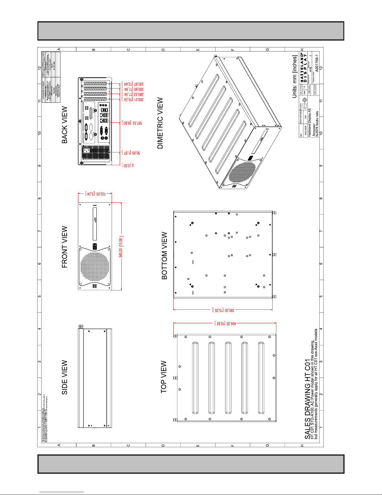
Technical Drawings - HT C01
34
INB100042-2 (Rev 14)
IND100132-149
AC Model
This document is the property of Hatteland Display AS. This document and any authorized reproduction thereof, must not be used in any way against the interest of Hatteland Display AS.
Any authorized reproduction, in whole or in part, must include this legend. Hatteland Display Proprietary information. Not to be distributed to any third party without written permission.
Dimensions might be shown with or without decimals and indicated as mm [inches]. Tolerance on drawings is +/- 1mm. For accurate measurements, check relevant DWG le.
Page 35
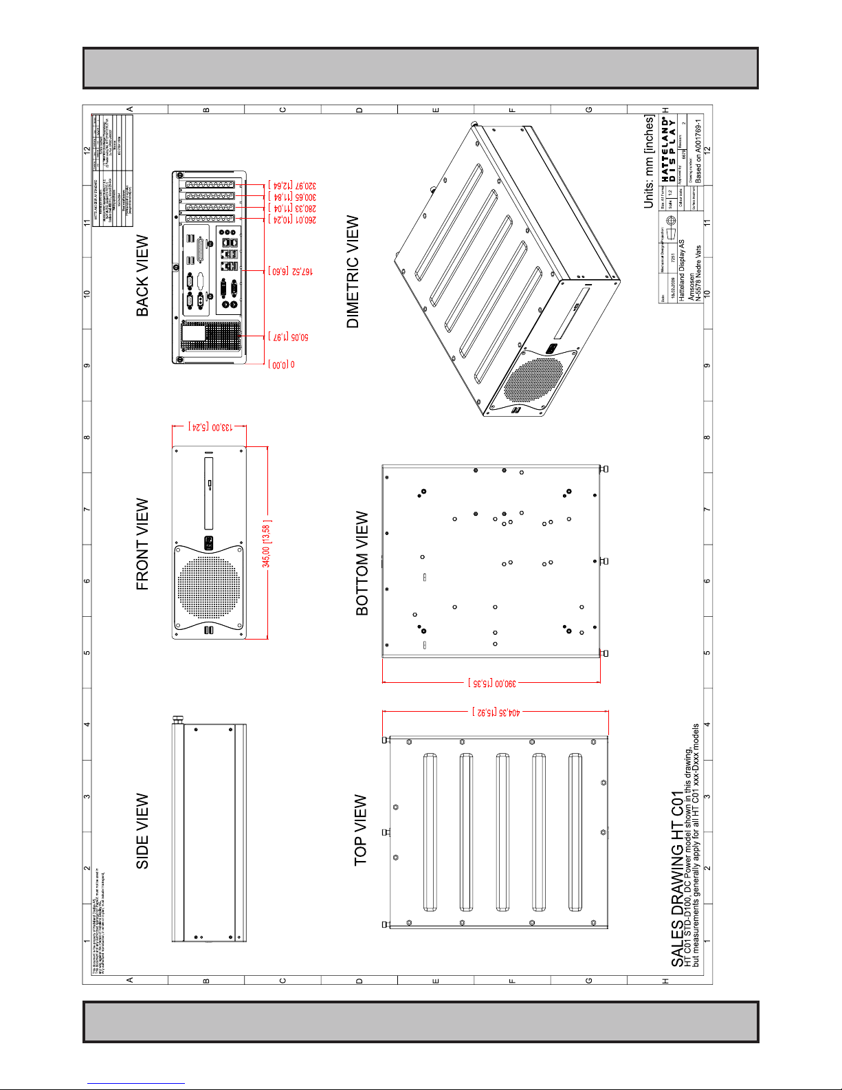
Technical Drawings - HT C01
35
INB100042-2 (Rev 14)
IND100132-149
DC Model
Page 36

36
INB100036-3 (Rev 4)
This page left intentionally blank
Page 37

37
INB100042-2 (Rev 14)
Technical Drawings - Accessories
Page 38
38
INB100042-2 (Rev 14)
IND100132-163
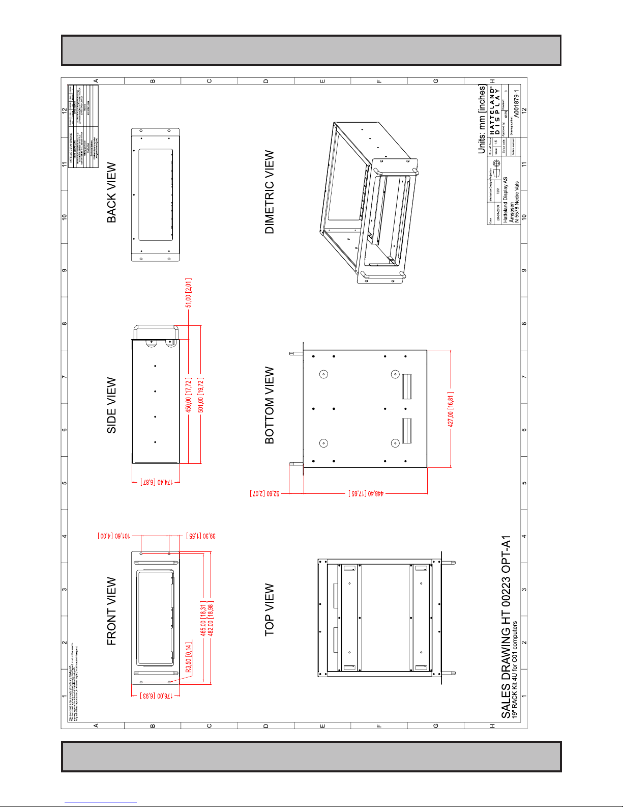
This document is the property of Hatteland Display AS. This document and any authorized reproduction thereof, must not be used in any way against the interest of Hatteland Display AS.
Any authorized reproduction, in whole or in part, must include this legend. Hatteland Display Proprietary information. Not to be distributed to any third party without written permission.
Dimensions might be shown with or without decimals and indicated as mm [inches]. Tolerance on drawings is +/- 1mm. For accurate measurements, check relevant DWG le.
Technical Drawings - 19” Rack Kit 4U
Page 39
Technical Drawings - 19” Rack Kit 4U
39
INB100042-2 (Rev 14)
IND100132-163
This document is the property of Hatteland Display AS. This document and any authorized reproduction thereof, must not be used in any way against the interest of Hatteland Display AS.
Any authorized reproduction, in whole or in part, must include this legend. Hatteland Display Proprietary information. Not to be distributed to any third party without written permission.
Dimensions might be shown with or without decimals and indicated as mm [inches]. Tolerance on drawings is +/- 1mm. For accurate measurements, check relevant DWG le.
Page 40
40
INB100042-2 (Rev 14)
IND100132-164
This document is the property of Hatteland Display AS. This document and any authorized reproduction thereof, must not be used in any way against the interest of Hatteland Display AS.
Any authorized reproduction, in whole or in part, must include this legend. Hatteland Display Proprietary information. Not to be distributed to any third party without written permission.
Dimensions might be shown with or without decimals and indicated as mm [inches]. Tolerance on drawings is +/- 1mm. For accurate measurements, check relevant DWG le.
Technical Drawings - Mounting Brackets
Page 41

41
INB100042-2 (Rev 14)
Appendixes
Page 42
42
IND100241-2
INB100042-2 (Rev 14)
Appendix
Pin Assignments - 5P PS/2 MOUSE
Pin 1: Mouse Data
Pin 3: Ground
Pin 5: Mouse Clock
Pin 2: Not Connected
Pin 4: Vcc +5V
Pin 6: Not Connected
Pin Assignments - USB TYPE A
Pin 2: Negative Data
Pin 1: VCC +5V
Pin 3: Positive Data
Pin 4: Ground
Pin Assignments - RJ45 10/100 LAN
Use category 5 - twisted pair cable
1 2 3 4 5 6 7 8
Pin 01 - TDP Transmit Differential Pair (Positive)
Pin 02 - TDN Transmit Differential Pair (Negative)
Pin 03 - RDP Receive Differential Pair (Positive)
Pin 04 - NC Not Connected
Pin 05 - NC Not Connected
Pin 06 - RDN Receive Differential Pair (Negative)
Pin 07 - NC Not Connected
Pin 08 - NC Not Connected
Pin Assignments - 9P Serial COM RS-232
This connector is commonly used for:
5 4 3 2 1
9 8 7 6
Pin 01 - DCD Data Carry Detect
Pin 02 - SIN Serial In or Receive Data
Pin 03 - SOUT Serial Out or Transmit Data
Pin 04 - DTR Data Terminal Ready
Pin 05 - GND Ground
Pin 06 - DSR Data Set Ready
Pin 07 - RTS Request To Send
Pin 08 - CTS Clear To Send
Pin 09 - RI Ring Indicate
Pin Assignments - Common Connectors
Pin Assignments - RJ45 10/100/1000 GBLAN
Pin 01 - D0P Differential Pair 0 (Positive)
Pin 02 - D0N Differential Pair 0 (Negative)
Pin 03 - D1P Differential Pair 1 (Positive)
Pin 04 - D2P Differential Pair 2 (Positive)
Pin 05 - D2N Differential Pair 2 (Negative)
Pin 06 - D1N Differential Pair 1 (Negative)
Pin 07 - D3P Differential Pair 3 (Positive)
Pin 08 - D3N Differential Pair 3 (Negative)
1 2 3 4 5 6 7 8
Note: Not all connectors may be available on your specic product. This depends on the amount of additional hardware installed from factory,
or customized solutions. These pin assignments are for the common connectors used. Connectors are seen from users Point Of View (POV).
Pin Assignments - 15P HD RGB VGA
Pin 01
Red, analog
Pin 02 Green, analog
Pin 03 Blue, analog
Pin 04 Reserved for monitor ID bit 2 (grounded)
Pin 05 Digital ground
Pin 06 Analog ground red
Pin 07 Analog ground green
Pin 08 Analog ground blue
Pin 09 +5V power supply for DDC (optional)
Pin 10 Digital ground
Pin 11 Reserved for monitor ID bit 0 (grounded)
Pin 12 DDC serial data
Pin 13 Horizontal sync or composite sync, input
Pin 14 Vertical sync, input
Pin 15 DDC serial clock
5 4 3 2 1
15 14 13 12 11
10 9 8 7 6
Pin Assignments - 5P PS/2 KEYBOARD
Pin 1: Keyboard Data
Pin 3: Ground
Pin 5: Keyboard Clock
Pin 2: Not Connected
Pin 4: Vcc +5V
Pin 6: Not Connected
Pin Ass. - 5P PS/2 KEYBOARD+MOUSE Combined
Pin 1: Keyboard Data
Pin 3: Ground
Pin 5: Keyboard Clock
Pin 2: Mouse Data
Pin 4: Vcc +5V
Pin 6: Mouse Clock
Pin Assignments - USB TYPE B
Pin 2: Negative Data
Pin 3: Positive Data
Pin 4: Ground
Pin 1: VCC +5V
Pin Assignments - FIREWIRE IEEE-1394
Pin 01 - VCC Power
Pin 02 - GND Grounding for power and inner cable shield
Pin 03 - TPB- Twisted Pair B- Receive Strobe, Transmit Data
Pin 04 - TPB+ Twisted Pair B+ Receive Strobe, Transmit Data
Pin 05 - TPA- Twisted Pair A- Transmit Strobe, Receive Data
Pin 06 - TPA+ Twisted Pair A+ Transmit Strobe, Receive Data
1
3
5
2
4
6
Pin Assignments - 5P S-VHS/S-VIDEO
Pin 1: Ground (Y)
Pin 3: Y - Intensity (luminance)
Pin 2: Ground (C)
Pin 4: C - Color (chrominance)
Pin Assignments - RCA/BNC 1P COMP. VIDEO
Ground Shield
Pin 1: Video Signal
Note: The table above lists commonly-used RS-232 signals and pin
assignments, however Serial Communication for Hatteland Display products
may vary from product to product to support different end user systems.
Please check additional pin assignments section in this manual for specic
RS-232/RS-422/RS-485 pin assignments for your exact product.
Page 43
Pin Assignments - Common Connectors
43
IND100241-2
INB100042-2 (Rev 14)
Appendix
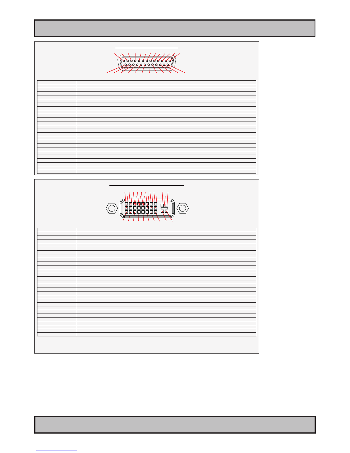
Pin Assignments - 25P Parallel
Pin 01 - STROBE This signal indicates to the printer that data at PD7..0 are valid.
Pin 02 - DATA0 Parallel data bus from PC board to printer. The data line are able to operate in PS/2 compatible bi-directional mode.
Pin 03 - DATA1 Same as Pin 02
Pin 04 - DATA2 Same as Pin 02
Pin 05 - DATA3 Same as Pin 02
Pin 06 - DATA4 Same as Pin 02
Pin 07 - DATA5 Same as Pin 02
Pin 08 - DATA6 Same as Pin 02
Pin 09 - DATA7 Same as Pin 02
Pin 10 - ACK Signal from printer indicating that the printer has received the data and is ready to accept further data.
Pin 11 - BUSY Signal from printer indicating that the printer cannot accept further data.
Pin 12 - PE Signal from printer indicating that the printer is out of paper.
Pin 13 - SELECT Signal from printer to indicate that the printer is selected.
Pin 14 - AUTO FEED This active low output causes the printer to add a line feed after each line printed.
Pin 15 - ERR# Signal from printer indicating that an error has been detected.
Pin 16 - INIT# This active low output initialises (resets) the printer.
Pin 17 - SLIN# Signal to select the printer sent from CPU board to printer.
Pin 18 - GND Ground
Pin 19 - GND Ground
Pin 20 - GND Ground
Pin 21 - GND Ground
Pin 22 - GND Ground
Pin 23 - GND Ground
Pin 24 - GND Ground
Pin 25 - GND Ground
13 12 11 10 9 8 7 6 5 4 3 2 1
25 24 23 22 21 20 19 18 17 16 15 14
Pin Assignments - 24P DVI-D & DVI-I
Pin 01 T.M.D.S. Data2 - (Digital - RED link 1)
Pin 02 T.M.D.S. Data2 + (Digital + RED link 1)
Pin 03 T.M.D.S. Data2/4 Shield
Pin 04 T.M.D.S. Data4 - (Digital - GREEN link 2)
Pin 05 T.M.D.S. Data4 + (Digital + GREEN link 2)
Pin 06 DDC Clock
Pin 07 DDC Data
Pin 08 Analog Vertical Sync (DVI-I only)
Pin 09 T.M.D.S. Data1 - (Digital - GREEN link 1)
Pin 10 T.M.D.S. Data1 + (Digital + GREEN link 1)
Pin 11 T.M.D.S. Data1/3 Shield
Pin 12 T.M.D.S. Data3 - (Digital - BLUE link 2)
Pin 13 T.M.D.S. Data3 + (Digital + BLUE link 2)
Pin 14 +5V Power (for standby mode)
Pin 15 Ground (for +5V and analog sync)
Pin 16 Hot Plug Detect
Pin 17 T.M.D.S. Data0 - (Digital - BLUE link 1) and digital sync.
Pin 18 T.M.D.S. Data0 + (Digital + BLUE link 1) and digital sync.
Pin 19 T.M.D.S. Data0/5 Shield
Pin 20 T.M.D.S. Data5 - (Digital - RED link 2)
Pin 21 T.M.D.S. Data5 + (Digital - RED link 2)
Pin 22 T.M.D.S. Clock Shield
Pin 23 T.M.D.S. Clock + (Digital clock + (Links 1 and 2)
Pin 24 T.M.D.S. Clock - (Digital clock - (Links 1 and 2)
Pin C1 Analog RED
Pin C2 Analog GREEN
Pin C3 Analog BLUE
Pin C4 Analog Horizontal Sync.
Pin C5 Analog Ground (return for RGB signals)
DDC = Display Data Channel /// T.M.D.S = Transition Minimized Differential Signal /// PIN C1,C2,C3,C4 = Only present on DVI-I connectors.
NOTE: Connector shows a DUAL LINK design, but some units may not support it. Only products with 1920x1200 or more in resolution
require / support DUAL LINK.
1 2 3 4 5 6 7 8 C1 C2
9 10 11 12 13 14 15 16 C5
17 18 19 20 21 22 23 24 C3 C4
Additional connector pinouts may be available in third party motherboard manuals, primarly for
computers only. Please see manual/drivercd delivered with your product or own section in this
user manual.
Page 44
44
IND100077-91
INB100042-2 (Rev 14)
Appendix
Trouble-shooting
GENERAL TROUBLE-SHOOTING
CD-ROM FAILURE OR READ/DETECTION PROBLEMS?
If the product are operated/located in a area with extreme condensation, the CD/DVD-ROM drive may not work
correctly due to condensation on the read head. Keep the product on for a while until it’s reached normal operating
temperature, and retry accessing discs. Otherwise, consider using USB memory sticks or alternative storage devices.
NO CD-ROM AVAILABLE ON YOUR PRODUCT FOR INSTALLING DRIVERS/SOFTWARE?
Please use USB memory sticks, USB Floppy drive, USB CD-Rom Drive or alternative storage devices to transfer or
install software on CD-ROM-less units.
RECOVERY/RESCUE IMAGE
IND101744-1 rev 01 - 16 Jun 2011 - 6987/6923/363
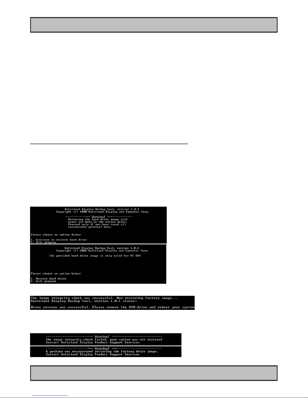
RECOVERY / RESCUE IMAGE - QUICK START
The Recovery Kit (USB Flash) media access a hidden partition image located on factory delivered units with HDD/
SDD hardware installed. This image is not accessible from any operating system, only by the Recovery Kit (USB
Flash) provided by Hatteland Display.
Note that all les created after rst time factory boot will be DELETED!
Restore from external USB recovery image (HT 00215 OPT-A1):
1: Insert the USB Flash media into the computer usb connector.
2: Restart the computer.
3: On the rst screen that appear, press “Delete” or “F2” on the keyboard (depending on BIOS model) to bring up
the BIOS setup screen.
4: Select “Advanced BIOS features” or “Boot“ (depending on BIOS model).
5: Set “Harddisk boot priority” to “USB HDD” as number 1
or select "Hard Disk Drives", then modify "1 st" to "USB: ...." depending on BIOS model.
6: Press F10 and then Enter on keyboard, or “F4” to save settings (depending on BIOS model).
7: Follow the on screen instructions that will be executed from the USB Flash media, such as;
8: After the restore operation is complete, remove the USB Flash Media and restart.
9: The computer is now restored to its original factory state.
10: If rescue failed, an error message will be displayed.
Page 45
IND100237-1
Declaration of Conformity
We, manufacturer
Hatteland Display AS
Åmsosen, N-5578 Nedre Vats, Norway
declare under our sole responsibility that the
JH MMD, JH MMC, JH STD, JH MIL, HM NMD, HM MIL,
HM CMD, HT STD, HD MMD, HM MMD & HT MMC
product ranges is in conformity with the following
standards in accordance with the EMC Directive.
Low Voltage Directive 2006/95/EC
EN 60950
EMC Directive 2004/108/EC
EN 55022 Class A
EN 55024
Signature:........................................................
Frode Grindheim
Vice President Product Management
Nedre Vats, Norway
CE MARK FIRST AFFIXED DATE (11 March 2010)
Signature:........................................................
Arne Kristiansen
Site Manager - Test & Commission Division
Oslo, Norway
Page 46

46
IND100077-14
INB100042-2 (Rev 14)
Appendix
Return of goods:
(Applies not to warranty/normal service/repair of products)
Hatteland Display referenced as “manufacturer” in this document.
Before returning goods, please contact your system supplier before sending anything directly to manufacturer. When
you return products after loan, test, evaulation or products subject for credit, you must ensure that all accessories
received from our warehouse is returned. This applies to cables, powermodules and additional equipment except
screws or similar, user manual, datasheets or other written paper documents. Furthermore, the product must not have
any minor / medium or severe scratches, chemical spills or similar on the backcover, front frame or glass.
This is needed to credit the invoice 100%. Missing parts will not be subject for credit, and you will not get total credit
for returned product. You will either be charged separately or the amount is withdrawn from the credit. If you decide to
ship the missing items on the after hand, you will get 100% credit for that particular invoice or items received at
manufacturer incoming goods control. Please contact our service/sales department if additional questions
Approved packaging methods/materials:
(Applies to all shipments to manufacturer)
When returning goods, please make sure you surround the product with the following material, whenever possible:
Original packaging from manufacturer, rm foam material, bubble wrap or lots of PadPack paper or Foam chips/polyester wrapped in sealed plastic bags. In any case, always use a solid cardboard box to surround everything.
Not approved packaging methods/materials are: Foam chips, expanded polyester, clothes, nothing, or too little, or
anything that will crumble and get into the ventilation holes of products and cardboard boxes that are not suitable to
secure the product during shipment.
Return Of Goods Information
Page 47

47
IND100077-7
INB100042-2 (Rev 14)
Appendix
Terms
Terms Of Sale And Delivery
1) APPLICATION
The terms of sale and delivery apply for Hatteland Display.
2) PRICE
a) The price is per each, if nothing else has been stated, VAT not included. Price is based on the prices from our suppliers, current
custom rates, taxes, rate of exchange and international raw material prices. We reserve ourselves the rights to adjustments in case
of alternation on the above mentioned.
b) Included in the price is the supplier’s standard packing. In case of re-packing/smaller quantities we reserve ourselves the right to
add an additional sum for warrantable packing according to CECC 0015 (Basic inspection for protection of electrostatic sensitive
devices)
3) VALIDITY
If nothing else has been stated in our quotation, the offer is valid for 30 days from the date of quotation.
4) PACKAGE QUOTATION
A package quotation means that all the components offered, must be ordered by us. If one component or more are removed from the
quotation, the prices given in the package quotation are not valid.
5) TERMS OF PAYMENT
Cash on delivery or payment in advance. Net granted for companies, schools and institutions only, according to agreement. In case of
too late payment 1.5% interest/month will be charged. Seller has mortage rights in the goods delivered until the purchase price,
additional interests and charges have been paid in full. Accepted bill is not considered as payment until it has been honoured in full.
6) TIME OF DELIVERY
The quoted time of delivery is based on information from our suppliers. We disclaim any responsibility for the consequences of any
delay or cancellation from our suppliers. Belated delivery gives not solely the right for cancellation.
7) DELIVERY POINT OF TIME
Goods are considered delivered to customer when handed over to charterer.
8) FREIGHT / PACKING / FORWARDING FEE
Hatteland Display AS charge NOK 50,- in forwarding fee for orders below NOK 1000,-.
Freight charge according to expenses for orders above NOK 1000,-. VAT not included.
9) COMPLAINT
By receipt customer must check goods for obvious defects which have to be claimed within 8 days from receipt. Otherwise acceptance
of complaint can not be counted on.
10) GUARANTEE / SERVICES
Time of guarantee is calculated from our date of shipment, and applies to the extent that we are covered by our supplier’s guarantee
regulations. The guarantee does no longer apply if:
I) there has been encroached upon the goods without seller’s consent
II) terms of payment is not fullled
III) the goods have been damaged due to unskilled treatment
IV) components which are sensitive for static electricity have not been unpacked and treated in a secure way.
Minimum requirements: CECC 00015’s standards for handling of such components. The guarantee does not include fair wear and tear.
11) RESPONSIBLITY
Seller undertake to deliver faultless and functional capable goods according to existing technical specications. Seller disclaim
responsibility for any damage or loss which directly or indirectly may be caused due to failure or defect with the delivered goods, if
carelessness from the seller can be limited up to the cost of the goods. The supplier’s responsibility for defects with the supplied
goods do not include secondary damage or loss.
Page 48

48
IND100077-7
INB100042-2 (Rev 14)
Appendix
Terms
INSTRUCTIONS FOR THE CONSIGNEE
12) CANCELLATION / RETURN
Binding sales contract is concluded when we have conrmed customer’s purchase order. Any disagreements in our order conrmation
must be reported to seller within 6 days. The agreement can not be altered without our permission, after acceptance from our
supplier. If goods are wanted to be returned, a Return No must be assigned from seller. Returned goods without a Return No will not
be accepted. By return of stock listed goods, 20% return fee is charged. Returned goods are shipped on customer’s account and risk.
13) LOAN, RENT and DEMO
When borrowing of goods for demo/test, the date of return must be added to the document. If no date has been stated, date of
return is two weeks from the date of the document. Before return, seller must be contacted for a Return No (RTK). Goods which have
been sold with an agreed right of return within stated terms, shall also have a Return No. The Return No must be obtained before the
stated date of return. Returned goods without a Return No, or which have not been packed in original packing, will not be accepted.
14) LIMITATIONS
If any of our suppliers claim limited delivery terms towards us, our terms of delivery will be restricted according to those.
15) SOFTWARE
Sold or borrowed software is not allowed to be copied or spread in other ways, without a written permission.
16) RE-EXPORT
Goods delivered from seller may be subject to special rules of exportation in their supplier’s native country. Buyer is responsible to obtain
necessary permissions for further export/re-sale.
17) QUESTION IN DISPUTE
To settle any dispute the Karmsund Herredsrett is approved the legal venue.
1) CONTROL
Control the goods immediately by receipt. Examine the quantity towards the invoice/packinglist/shipping documents. Look for outward
defects on the packing which may indicate damage on or loss of contents. Control the container and the seals for any defects.
2) SECURING EVIDENCE
When defects on the goods have been found, evidence must be secured, and seller must be informed. Call the transporter and point out the
defects. Add a description of the defects on the goods receipt, the forwarder’s copy of the way-bill or on the driving slip.
3) RESCUE
Bound the damage. Try to restrict the damage and the loss. Seller will compensate expences incurred due to reasonable security efforts in
addition to damage and loss.
4) COMPLAINT
Write immediately a complaint to the transporter or his agent. Forward immediately the complaint to the transporter or his agent, and hold
the transporter responsible for the defects. The complaint must be sent at the latest:
- for carriage by sea: within 3 days
- for overland / air transportation within 7 days
5) DOCUMENTATION
For any claims the following documentation is required, and must be forwared to the company or their agent: invoice, way-bill and/or bill of
landing, and/or statement of arrival, inspection document, besides a copy of the letter of complaint to the transporter.
Page 49
49
IND100077-24
INB100042-2 (Rev 14)
Appendix
Notes
Page 50
50
IND100077-83
INB100042-2 (Rev 14)
Rev. By Date Notes
0 SEJENov 2008/Jan
2009
Release for internal reviews
1 SE
JE
PT
27 Feb 2009 Release of nal rev1 for internet
2 SE
GOS
26 Mar 2009 Update specications and installation recommendations.
3 SEJE19 May 2009 Updated specications.
Added drawings and information about 19” Rack Kit 4U, Sliding Rails and Mounting Brackets accessories.
4 SEJE28 May 2009 Replaced trouble shooting chapter with specic HTC01 troubleshooting and instructions for
recovery image.
5 SE
JE
09 Jul 2009 Revised drawings for 19” Rack Kit HTC01, 4U. (Page 36,37)
Revised specications (Testing page 32)
6 JESE10 Sep 2009 Added note about HDD/SDD future sizes (page 32)
7 AK
JE
SE
29 Oct 2009 Revised text elements in contents of package page 5
Added computers introduction page 9
Removed LRS type approval text on specications page 32.
Revised drawings for 19” Rack Kit HTC01, 4U. (Page 37) (Panhead screws should be M6x8)
Revised specications (ABS Type Approval) Page 32
8 JESE19 Nov 2009 Revised contents of package (3rd party hardware box text) page 4
Revised specications (HDD 120GB->250GB + remove A356) page 32
9 AKSE03 Dec 2009 Added Nippon and BV Type Approved (page 32)
10 AKSE21 Jan 2010 Added DNV Type Approved (page 32)
11 JESE02 Sep 2010 Added info regarding DC Dxxx models (page 1, 5, 11, 14, 28, 32,34)
Added GL Type Approval (page 32)
Added LRS Type Approval (pending) page 32
Change Axxx to yx xx to conform with both AC and DC models (Axxx = AC, Dxxx = DC)
12 JESE08 Mar 2011 Revised company related text (page 1,8)
Revised Contents of Package (user manual/documentation dvd) (page 5)
Revise DVI-I text (added note) (page 29)
Added Technical Drawings for Sliding Rails HT 00224 and HT 00225 (page 39,40)
Minor text changes for Recover y CD functionality (page 44)
13 JESE30 Mar 2011 Revised specications, added LRS type approval and Operating System ID (page 11,32)
14 JE
SE
20 Jun 201 Revised contents of package (HT 00215OPT) (page 5)
Added note about HDD replacement for DC models, power must be dismounted as well (page 20)
Added BV approval for DC, ABS, GL to specications (page 32)
Added DC model drawing (page 35)
Revised Recovery Kit (USB Flash) HT 00215 OPT User Guide (page 44)
Revision History
Page 51

51
INB100024-2 (Rev 9)
This page left intentionally blank
Page 52

www.hatteland-display.com
 Loading...