

Page 1
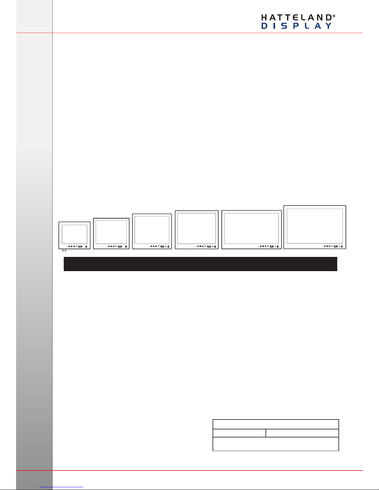
HD 12T21 MMD-xxx-Fxxx - 12.1 inch Maritime Multi Display
HD 15T21 MMD-xxx-Fxxx - 15.0 inch Maritime Multi Display
HD 17T21 MMD-xxx-Fxxx - 17.0 inch Maritime Multi Display
HD 19T21 MMD-xxx-Fxxx - 19.0 inch Maritime Multi Display
HD 24T21 MMD-xxx-Fxxx - 24.0 inch Maritime Multi Display
HD 26T21 MMD-xxx-Fxxx - 25.54 inch Maritime Multi Display
Series X - Maritime Multi Display (MMD) Models
USER MANUAL
Hatteland Display AS, Åmsosen, N-5578 Nedre Vats, Norway
Tel: (+47) 4814 2200 - [email protected] - www.hatteland-display.com
Please visit www.hatteland-display.com for the latest electronic version of this manual.
User Manual MMD Series X
Updated: 10 Jan 2013 Doc Id: INB100519-1 (Rev 5)
Created: 363
Approved: 6542
Page 2

Copyright © 2013 Hatteland Display AS
Aamsosen, N-5578 Nedre Vats, Norway.
All rights are reserved by Hatteland Display AS. This information may not, in whole or in part, be
copied, photocopied, reproduced, translated or reduced to any electronic medium or machine-
readable form without the prior written consent of Hatteland Display AS. Review also:
www.hatteland-display.com/pdf/misc/doc100703-1_permission_to_create_user_manuals.pdf
The products described, or referenced, herein are copyrighted to the respective owners.
The products may not be copied or duplicated in any way. This documentation contains proprietary
information that is not to be disclosed to persons outside the user’s company without prior written consent
of Hatteland Display AS.
The copyright notice appearing above is included to provide statutory protection in the event of
unauthorized or unintentional public disclosure.
All other product names or trademarks are properties of their respective owners !
WARNING: This is a class A product. In a domestic environment this product may cause radio interference
in which case the user may be required to take adequate measures.
Last revised 9 Nov 2012
Page 3
3
IND100130-43
Contents .......................................................................................... 3
Contents of package ..................................................................................6
General ............................................................................................ 7
About this manual ......................................................................................8
About Hatteland Display ............................................................................8
www.hatteland-display.com ........................................................................8
Contact Information ....................................................................................8
Maritime Multi Display (MMD) - Introduction ..............................................9
Product Labeling ......................................................................................10
Labels and Locations ...................................................................10
Typenumber Structure (example) .................................................10
Warranty Label .............................................................................10
Quality Control (QC) Label ...........................................................10
Installation ..................................................................................... 11
First Things First! .....................................................................................12
Installation and mounting .........................................................................12
Ergonomics ..............................................................................................14
Cables ......................................................................................................14
Cable Entries & Connectors (Marked area) - Illustration only ......14
Maximum Cable Length ...............................................................15
Conguring housing connectors ..............................................................15
Panel / Console Mounting Key Hole Bracket Kit for 12”,15”,17”,19” ........16
Panel Cutout / Console Mounting Bracket Kit for 24”,26” ........................17
Mounting Bracket for Table / Desktop installation - 12”,15”,17”,19” .........18
Mounting Bracket for Table / Desktop installation - 24”,26” .....................20
Physical Connections ...............................................................................21
Contents
Page 4
Contents
4
IND100130-43
Operation ....................................................................................... 25
User Controls ...........................................................................................26
On Screen Display (OSD) Menu Introduction ..........................................28
OSD Keycode / OSD Lock Mode .............................................................28
OSD Simplied and Full Menu modes (examples) ..................................29
OSD Visual Feedback (examples) ...........................................................29
OSD Menu Structure ................................................................................30
Input Source Settings (page 30-31) .............................................30
Image Settings (page 32-36) ........................................................30
Color Mode Settings (page 37) ....................................................31
Multi-PIP Settings (page 38-39) ...................................................31
OSD Settings (page 40-43) ..........................................................32
Management Settings (page 44-49) .............................................33
Service Settings (page 50-51) ......................................................33
On Screen Display (OSD) Menu Functions .............................................34
Specications ............................................................................... 57
Specications - HD 12T21 MMD-xxx-Fxxx ..............................................58
Specications - HD 15T21 MMD-xxx-Fxxx ..............................................59
Specications - HD 17T21 MMD-xxx-Fxxx ..............................................60
Specications - HD 19T21 MMD-xxx-Fxxx ..............................................61
Specications - HD 24T21 MMD-xxx-Fxxx ..............................................62
Specications - HD 26T21 MMD-xxx-Fxxx ..............................................63
Technical Drawings ...................................................................... 65
Technical Drawings - HD 12T21 MMD-xxx-Fxxx .....................................66
Technical Drawings - HD 15T21 MMD-xxx-Fxxx .....................................67
Technical Drawings - HD 17T21 MMD-xxx-Fxxx .....................................68
Technical Drawings - HD 19T21 MMD-xxx-Fxxx .....................................69
Technical Drawings - HD 24T21 MMD-xxx-Fxxx .....................................70
Technical Drawings - HD 26T21 MMD-xxx-Fxxx .....................................71
Technical Drawings - Accessories .............................................. 73
Console Mount Kit 12”,15”,17”,19” ...........................................................74
Console Mount Kit 24” .............................................................................75
Console Mounting 24” ..............................................................................76
Flush Mounting 24” ..................................................................................77
Page 5
Contents
5
IND100130-43
Appendixes ................................................................................... 79
Pinout Assignments .................................................................................80
Basic Trouble-shooting ............................................................................84
Declaration of Conformity ........................................................................85
Return Of Goods Information ...................................................................86
Terms .......................................................................................................87
Pixel Defect Policy ...................................................................................89
Notes ........................................................................................................90
Revision History .......................................................................................92
Page 6
6
IND100131-28
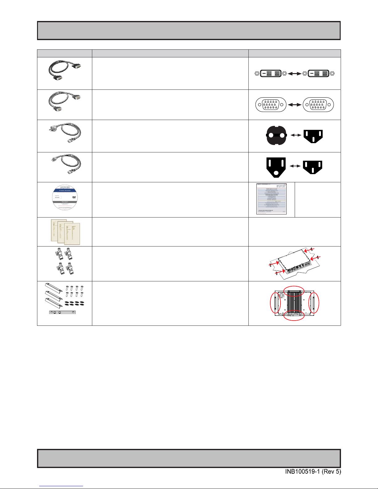
Contents of package
Item Description Illustration
HA-SDM-2M
1 pcs of Standard DVI Signal Cable.
DVI-D 18+1P Male to DVI-D 18+1P Male Single Link - Length 2.0m
HA-VGA-2M-32
1 pcs of Standard VGA Signal Cable.
DSUB 15P Male to DSUB 15P Male - Length 2.0m
FS-CABLE EU
1 pcs of power cable European Type F “Schuko” to IEC.
Length 1.8m
Note: Included in package for models with AC input.
EUR TYPE F
IEC
80099
1 pcs of power cable US Type B plug to IEC.
Length 1.8m
Note: Included in package for models with AC input.
US TYPE B
IEC
MEDIA STD01
Documentation and Driver DVD/CD containing the user manual, including the Touch
Screen driver for units delivered with a factory mounted touch screen.
In some cases (due to revisions) a provisonal CD (PRO02-xxx) may be delivered
with the product instead.
Menu and Driver
browser for
Microsoft® Windows®
Test Report
HD CMB SX1-A1
Model Dependent:
4 pcs of Key Hole Mounting Brackets for Console/Panel Mounting,
Anodized Aluminium/Stainless Steel. Suitable for panel thickness 3.0mm to 10.0mm.
This bracket kit is suitable for 12, 15, 17 and 19 inch units.
HD CMB SX1-B1 or
HD CMB SX1-C1
Model Dependent:
Bracket Kit suitable for console/panel mounting which contains:
3 x Mounting Bracket for top, left and right side
1 x Mounting Bracket for bottom side (terminal/connector plate area)
8 x M5x16 screws
8 x C-Washers
HD CMB SX1-B1 = Suitable only for 24 inch units.
HD CMB SX1-C1 = Suitable only for 26 inch units.
Page 7
7
General
Page 8
8
Hatteland Display AS
IND100077-1
General
About this manual
The manual contains electrical, mechanical and input/output signal specications. All specications in this manual,
due to manufacturing, new revisions and approvals, are subject to change without notice. However, the last update
and revision of this manual are shown both on the frontpage and also in the “Revision History” chapter at the end of
the manual.
Furthermore, for third party datasheet and user manuals, please see dedicated Documentation and Driver DVD
delivered with the product or contact our sales/technical/helpdesk personnel for support.
About Hatteland Display
Hatteland Display is the leading technology provider of specialized display and computer products, delivering high
quality, unique and customized solutions to the international maritime, naval and industrial markets.
The company represents innovation and quality to the system integrators world wide. Effective quality assurance and
investment in sophisticated in-house manufacturing methods and facilities enable us to deliver Type Approved and Mil
tested products. Our customer oriented approach, technical knowledge and dedication to R&D, makes us a trusted
and preferred supplier of approved solutions, which are backed up by a strong service network.
www.hatteland-display.com
You will nd our website full of useful information to help you make an informed choice as to the right product for your
needs. You will nd detailed product descriptions and specications for the entire range on Displays, Computers and
Panel Computers, Military solutions as well as the range of supporting accessories. The site carries a wealth of
information regarding our product testing and approvals in addition to company contact information for our various
ofces around the world, the global service centers and the technical help desk, all ensuring the best possible
support wherever you, or your vessel, may be in the world.
Contact Information
Head ofce, Vats / Norway:
Hatteland Display AS
Åmsosen
N-5578 Nedre Vats, Norway
Tel: +47 4814 2200
Fax: +47 5276 5444
Sales ofce, Frankfurt / Germany:
Hatteland Display GmbH
Werner Heisenberg Strasse 12,
D-63263 Neu-Isenburg, Germany
Tel: +49 6102 370 954
Fax: +49 6102 370 968
Sales ofce, Oslo / Norway:
Solbråveien 20
N-1383 Asker
Norway
Tel: +47 4814 2200
Fax: +47 5276 5444
Sales ofce, Aix-en-Provence / France:
Hatteland Display SAS
ACTIMART, 1140 RUE AMPERE, BP 50 196
13795 AIX-EN-PROVENCE, CEDEX 3
France
Tel: +33 (0) 4 42 16 47 57
Fax: +33 (0) 4 42 16 47 00
Sales ofce, San Diego / USA:
Hatteland Display Inc.
11440 W. Bernardo Court, Suite 300
San Diego, CA 92127, USA
Tel: +1 858 753 1959
Fax: +1 858-408-1834
For an up-2-date list, please visit www.hatteland-display.com/locations
Page 9
9
Displays Series X
IND101057-10
General
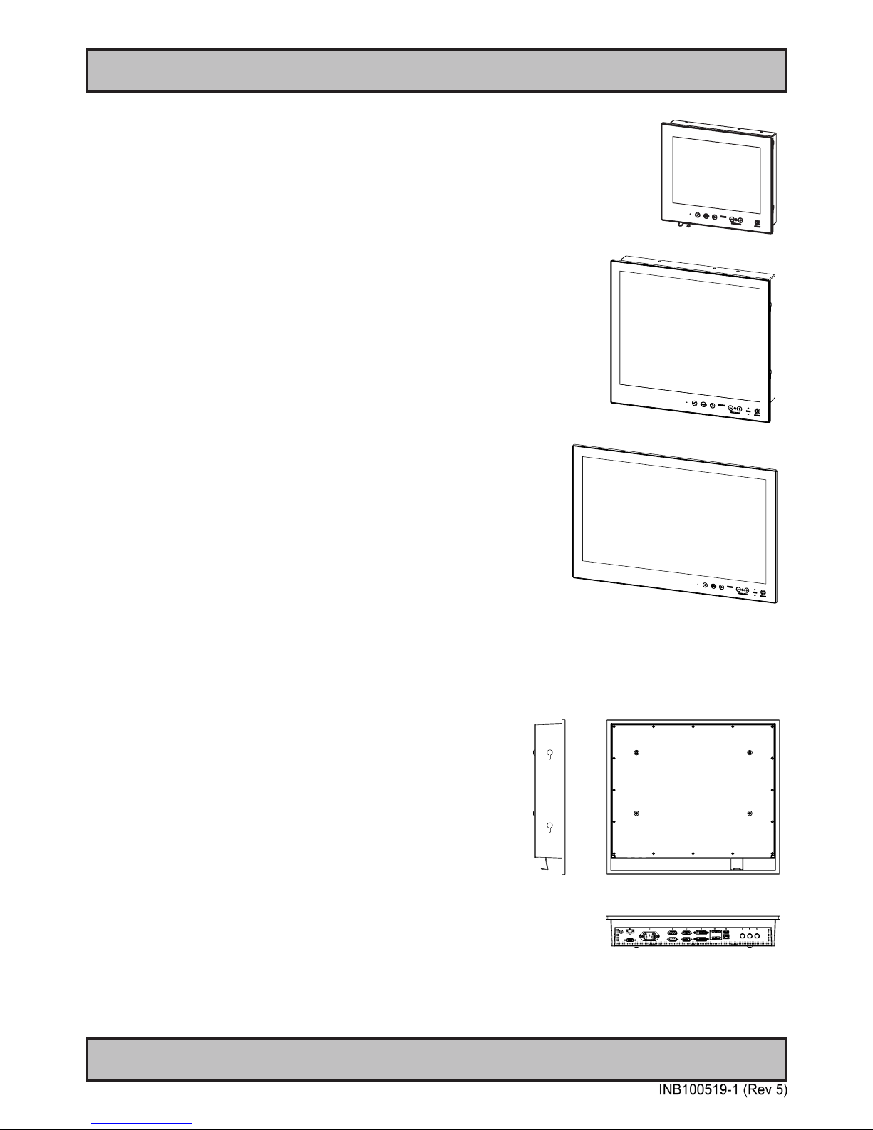
Maritime Multi Display (MMD) - Introduction
As a leading manufacturer of display and computer hardware for the maritime
segment, Hatteland Display continuously gauges and responds to market needs.
Our commitment to develop specialized products for a multitude of onboard ship
systems continues, and with that the introduction now of a
brand new product range called, Series X.
With cast aluminium, compact and sleek by design chassis, the units
from this new range can be desk mount or console integrated. The design
is modular, allowing for common modules to be used in various models and
combinations. Together these design features bring about a range perfectly
in synch to market cost expectations - along with that, the performance and type
approval always expected in all Hatteland Display products.
The modules used in Series X, are all qualified having undergone and passed
our extensive test program, which includes HALT testing. This means that the
products are tested well outside the requirements in EN60945 and E10. The
result is a more reliable product.
• MULTITOUCH
• TYPE APPROVED
• ECDIS COMPLIANT
• IP22 REAR / IP66 FRONT
• SUPERIOR BONDING TECHNOLOGY
• MODULE BASED, TAILOR-MADE SYSTEMS MADE EASY!
• SUNLIGHT READABLE / HIGH BRIGHT VERSIONS AVAILABLE
• GLASS DISPLAY CONTROL™ (GDC), SOLID STATE MENU SYSTEM
Page 10
10
IND100077-115
General
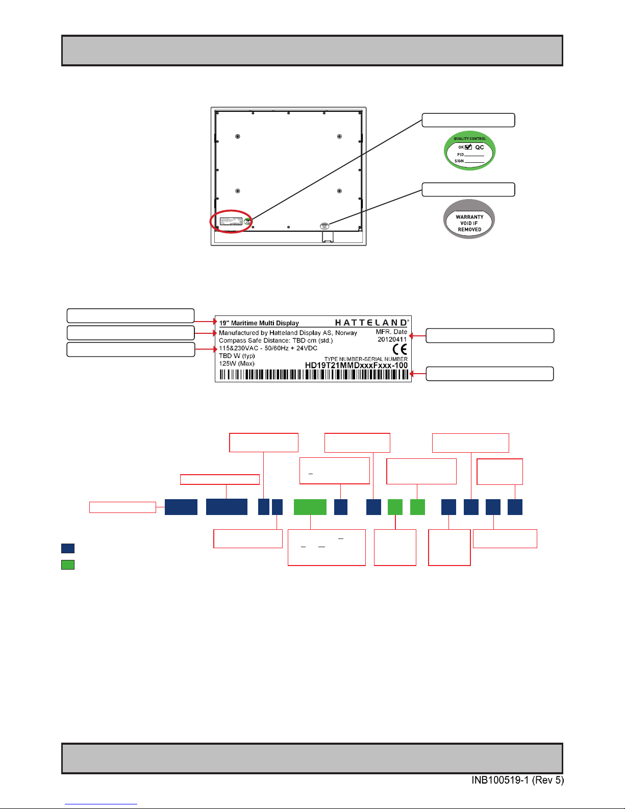
Labels and Locations
Product Labeling
Warranty Label
If you are to perform service on a unit still under warranty, any warranty will be void if this label show signs of removal
attempts (re-gluing) or removed completely. This label is located on the back of the product and covers a key screw.
This is to aid service departments to determine if there has been any unauthorized service on a unit still under
warranty.
Quality Control (QC) Label
This label indicates that the unit is produced, tested and packed according to manufacturer’s QA specications. It will
include a Personal ID and signature by the personnell responsible for approving the unit in production, test and
warehouse departments.
Warranty Label
Quality Control Label
Series X Displays - Typenumber Overview
IND100780-3 - Rev 06 - 02 Mar 2012
This document explains the type number structure for the
Hatteland Display Series X Maritime Multi Display product range.
- Example standard typenumber:
HD 19T21 MMD-MA1-FAGA
- Example standard description:
19.0” MMD ACDC Black GDC Buzzer
= Locked elements for factory standards.
= Custom/options - Can be customized by customer.
TFT Panel Size in inches
Product Range ID
PCB Electronics
Revision ID
Abbreviation for Maritime
Multi, STandard or
reserved for customer
company name ID
Product Type ID for
Display / Standard
(customer) Range ID
HD
19T
2
MMD
-
M
Power Input ID
A
Frame Color
or reserved
for customer
specicID
1
Standard ID or
reserved for
customerspecicID
F
-
Frame or
Mechanical
Design ID
A
Optical Enhancement ID
G
User Control
Functionality ID
A
Touch Screen
Technology ID
TFT Panel Generation
Revision ID
1
Series X Displays - Typenumber Overview
IND100780-3 - Rev 06 - 02 Mar 2012
This document explains the type number structure for the
Hatteland Display Series X Maritime Multi Display product range.
- Example standard typenumber:
HD 19T21 MMD-MA1-FAGA
- Example standard description:
19.0” MMD ACDC Black GDC Buzzer
= Locked elements for factory standards.
= Custom/options - Can be customized by customer.
Typenumber Structure (example)
Serial Number Label Layout (example)
Input Voltages & Power Rating
Label Size: 6cm x 2cm
Manufacturer & Country
Barcode Code128 (TYP+SNO)
Manufactured Date yyyymmdd
Product Type
Page 11
11
Installation
Page 12
12
IND100078-29
Installation
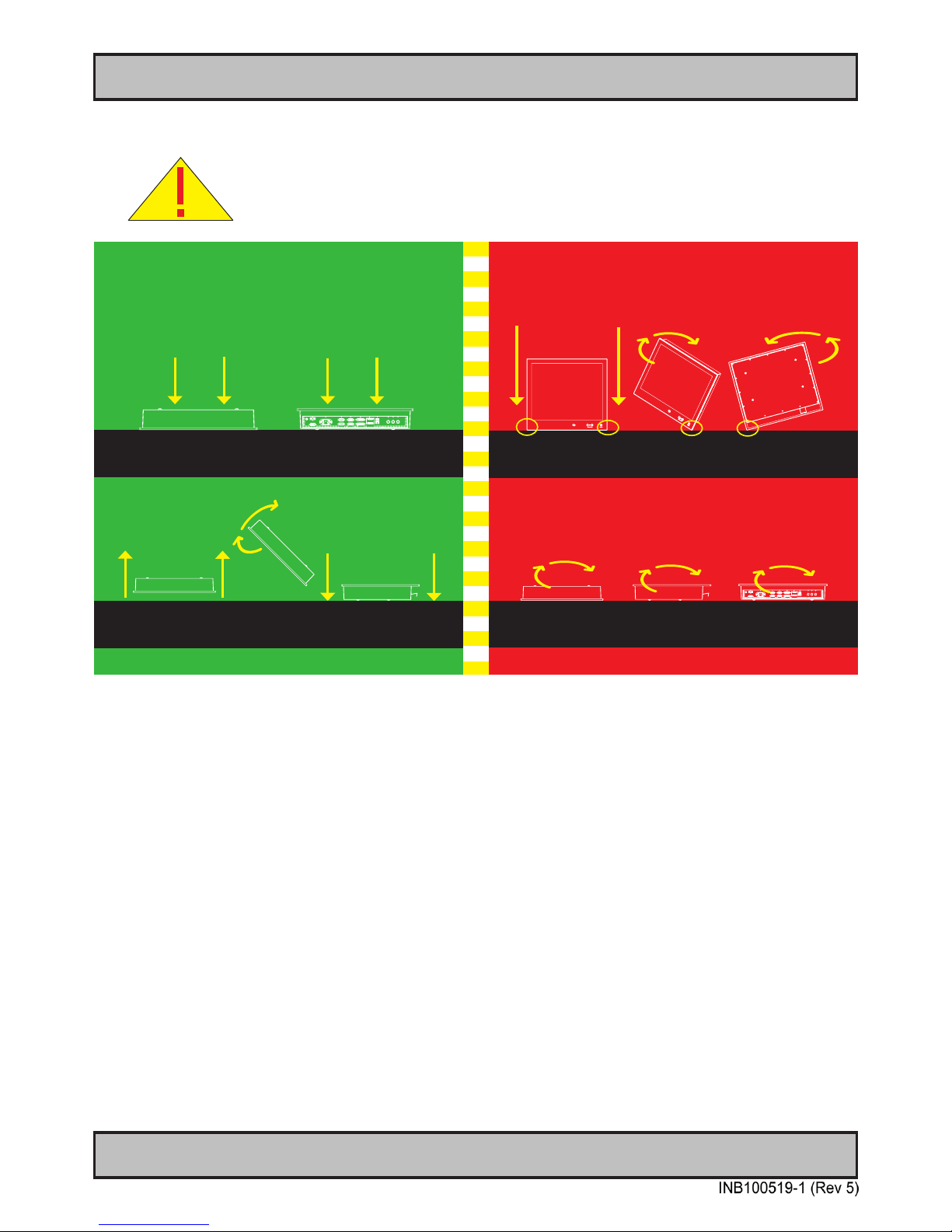
First Things First!
CORRECT HANDLING !
WRONG HANDLING !
Do not stress the corners, nor place
it on a coarse and/or dirty surface
Place horizontally on a smooth and clean surface
Place horizontally on a smooth and clean surface
Do not stress the corners, nor place
it on a coarse and/or dirty surface
To prevent damage to chassis and glass, please review the illustrations below before handling units.
IND100148-5 - Rev 02
ATTENTION!
Installation and mounting
1. Most of our products are intended for various methods of installation or mounting (panel mounting, bracket
mounting, ceiling/wall, console mounting etc.); for details, please see the relevant mechanical drawings.
2. Adequate ventilation is a necessary prerequisite for the life of the product. The air inlet and outlet openings must
denitely be kept clear; coverings which restrict ventilation are not permissible.
3. Generally, do not install the unit in a horizontal position (laying down), as this will cause heat to build up inside the
unit which will damage the LCD Panel. To prevent this problem we recommend installing the unit in a vertical
position (±30 degrees) to improve the airow through the unit.
4. To further improve the cooling of the unit we recommend installing Cooling Fans underneath blowing upwards into
the unit air inlet. This may be required in high temperature applications and also when there is reason to expect
temperature problems due to non-optimal way of mounting.
5. Exposure to extreme direct sunlight can cause a considerable increase in the temperature of the unit, and might
under certain circumstances lead to overtemperature. This point should already be taken into consideration when
the bridge equipment is being planned (sun shades, distance from the windows, ventilation, etc.)
6. Space necessary for ventilation, for cable inlets, for the operating procedures and for maintenance, must be
provided.
General Installation Recommendations
Page 13
13
IND100078-29
General Installation Recommendations
Installation
7. If the push buttons of the product are not illuminated, an external, dimmable illumination (IEC 60945 Ed. 4, 4.2.2.3,
e.g. Goose neck light) is required for navigational use. The illumination shall be dazzle-free and adjustable to
extinction.
8. Information about necessary pull-relievers for cables is indicated in the Physical Connection section of this manual.
Attention must be paid to this information so that cable breaks will not occur, e.g. during service work.
9. Do not paint the product. The surface treatment inuences on the excess heat transfer. Painting, labels or other
surface treatments that differ from the factory default, might cause overheating.
10. Expose to heavy vibration and acoustic noise might under certain circumstances affect functionality and expected
lifetime. This must be considered during system assembly and installation. Mounting position must carefully be
selected to avoid any exposure of amplied vibration.
General mounting instructions
1. The useful life of the components of all Electronics Units generally decreases with increasing ambient temperature;
it is therefore advisable to install such units in air-conditioned rooms. If there are no such facilities these rooms
must at least be dry, adequately ventilated and kept at a suitable temperature in order to prevent the formation of
condensation inside the display unit.
2. With most Electronic Units, cooling takes place via the surface of the casing. The cooling must not be impaired by
partial covering of the unit or by installation of the unit in a conned cabinet.
3. In the area of the wheel house, the distance of each electronics unit from the magnetic standard compass or the
magnetic steering compass must not be less than the permitted magnetic protection distance. This distance is
measured from the centre of the magnetic system of the compass to the nearest point on the corresponding unit
concerned.
4. Units which are to be used on the bridge wing must be installed inside the “wing control console” protected against
the weather. In order to avoid misting of the viewing screen, a 25 ... 50 W console-heating (power depending on the
volume) is recommended.
5. When selecting the site of a display unit, the maximum cable lengths have to be considered.
6. When a product is being installed, the surface base or bulkhead must be checked to ensure that it is at in order to
avoid twisting of the unit when the xing screws are tightened, because such twisting would impair mechanical
functions. Any unevenness should be compensated for by means of spacing-washers.
7. The grounding screws of the units must be connected to the body of the ship (ground); the wire used should have a
cross sectional area of at least 6 mm2.
8. Transportation damage, even if apparently insignicant at rst glance, must immediately be examined and be
reported to the freight carrier. The moment of setting-to-work of the equipment is too late, not only for reporting the
damage but also for the supply of replacements.
9. The classication is only valid for approved mounting brackets provided by Hatteland Display. The unit shall be
mounted stand-alone without any devices or loose parts placed at or nearby the unit. Any other type of mounting
might require test and re-classication.
Page 14
14
IND100078-29
General Installation Recommendations
Installation
Ergonomics
1. The front surface of the display glass has an anti-reective (AR) coating which can be scratched and damaged with
improper cleaning. It is recommended to use only 90+% pure Isopropyl alcohol (Isopropanol) and a soft fabric
cloth for this rst cleaning. Fold a cloth into a small pad, dampen the cloth with alcohol, and wipe the glass from
one edge to the other in one direction with one continuous motion. The product glass will require cleaning as
needed. The soft cloth & alcohol wipe is recommended to clean ngerprints and oils off the glass. Water stains
(including coffee, tea & coke) should be rst cleaned off the glass with a soft fabric cloth wet with water,
immediately followed with wiping using an alcohol wetted cloth.
2. Adjust the unit height so that the top of the screen is at or below eye level. Your eyes should look slightly
downwards when viewing the middle of the screen.
3. Adjust screen inclination to remain gaze angle to the centre of the screen approximately perpendicular to the line of
gaze.
4. When products are to be operated both from a sitting position and from a standing position, a screen inclination of
about 30° to 40° (from a vertical plane) has turned out to be favourable.
5. The brightness of displays is limited. Sunlight passing directly through the bridge windows - or its reection - which
falls upon the screen workplaces must be reduced by suitable means (negatively inclined window surfaces,
venetian blinds, distance from the windows, dark colouring of the deckhead). However, units can be offered with
optical enhanced technology and/or High Bright panels to reduce reections and are viewable in direct sun light,
but as a general rule the units at the bridge wing area is recommended to be installed or mounted by suitable
alignment or bulkhead / deckhead mounting in such a way that reections of light from the front pane of the display
are not directed into the observer’s viewing direction.
6. The use of ordinary commercial lter plates or lter lms is not permitted for items of equipment that require
approval (by optical effects, “aids” of that kind can suppress small radar targets, for example).
7. For ECDIS applications, the minimum recommended viewing distance are as follows:
(IEC62288, Part 7.5 Screen resolution)
17 inch = 908mm 19 inch = 1011mm 20 inch = 878mm 23 inch = 1011mm 27 inch = 1000mm
Cables
Use only high quality shielded signal cables.
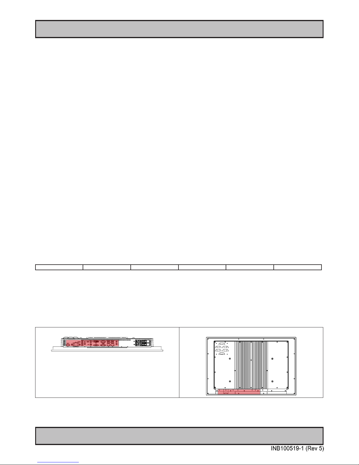
Cable Entries & Connectors (Marked area) - Illustration only
Bottom View Back View
Page 15
15
IND100078-29
General Installation Recommendations
Installation
Maximum Cable Length
Any cable should generally be kept as short as possible to provide a high quality input/output. The maximum signal
cable length will depend on the signal resolution and frequency, but also on the quality of the signal output from the
computer/radar.
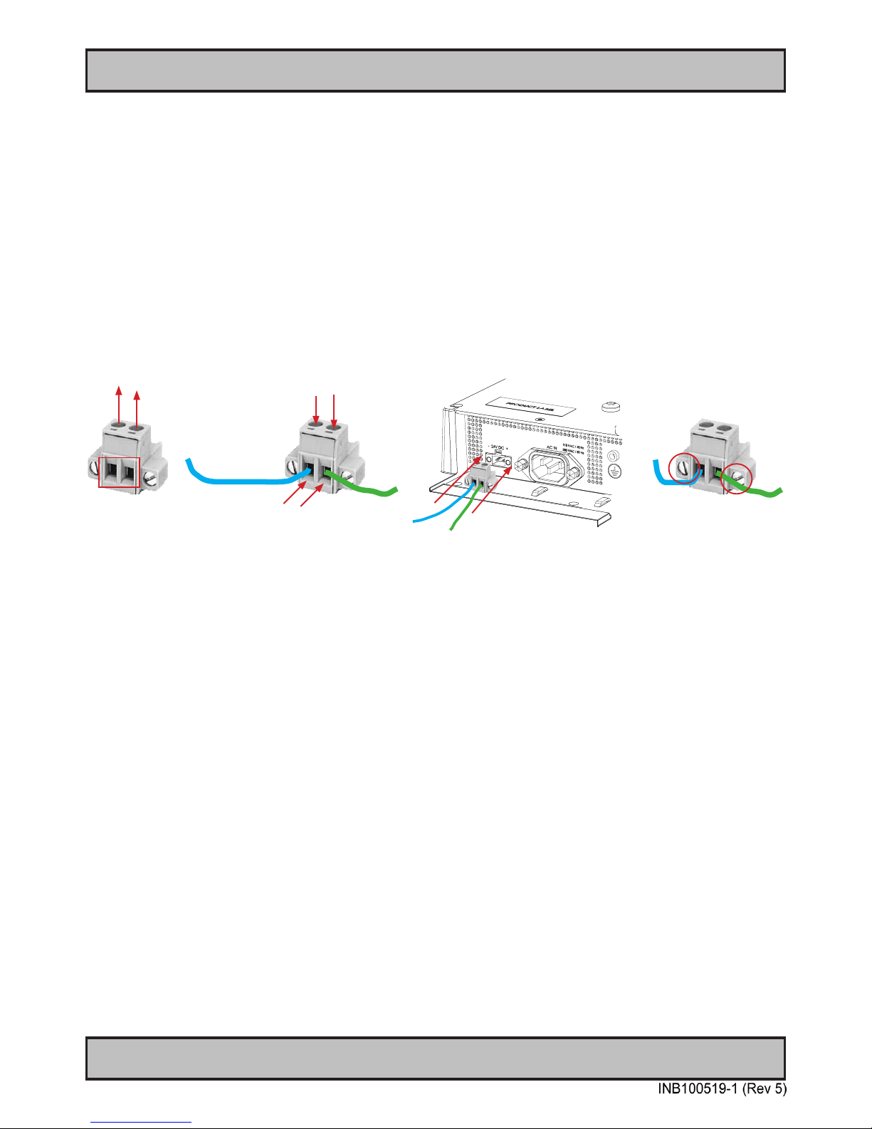
Conguring housing connectors
Housing connectors are available in different sizes (2-pin, 4-pin, 5-pin) which plugs into the connector area of the unit.
These housing connectors are by factory default mounted on the unit. Below is a brief illustration that might be useful
during conguration and installation of such connectors. You will need suitable pre-congured cable(s) and tools to
congure the connector(s) and cable(s) that are present in your installation environment. Below is a sample for a 2-pin
DC power connector. The procedure is the same for other connectors of this type.
FIG 1
FIG 3
FIG 2
FIG 4
FIG 1: Unscrew (from top) or make sure that the screw terminal (square area) are fully open, so you can secure the
inserted cables correctly to the loose housing connector (it may already be plugged into the unit as per factory
installation).
FIG 2: Insert cables* (from front) and screw / secure the cables by turning the screw on top of the housing to secure the
cables properly. Check that the cables is rmly in place and do not appear loose or falls out when pulling gently.
*Note: Required polarization verication (for instance -/+ for DC power input) should conform with the markings on the
connector area of the unit. Ignoring the markings on the unit or its add-on modules might damage the unit and/or external equipment in which end, warranty will be void.
FIG 3: Plug the housing into the appropriate connector area of the unit and check again that the cables secured
conforms with the markings on the connector area of the unit. Finalize the installation by fasten the screws located in
front on each side of the housing connector (FIG 4).
Page 16
16
Installation
IND100078-31
Installation Procedures
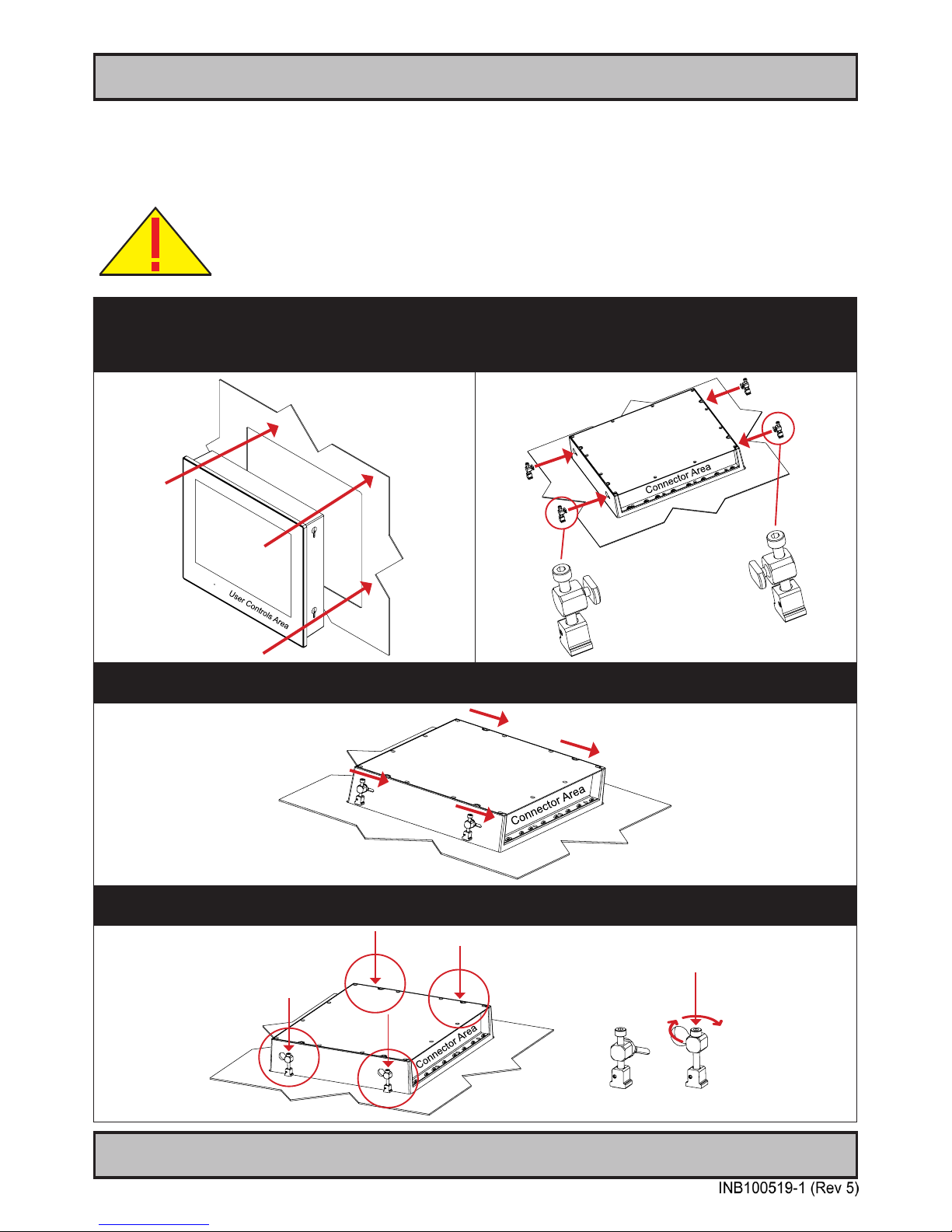
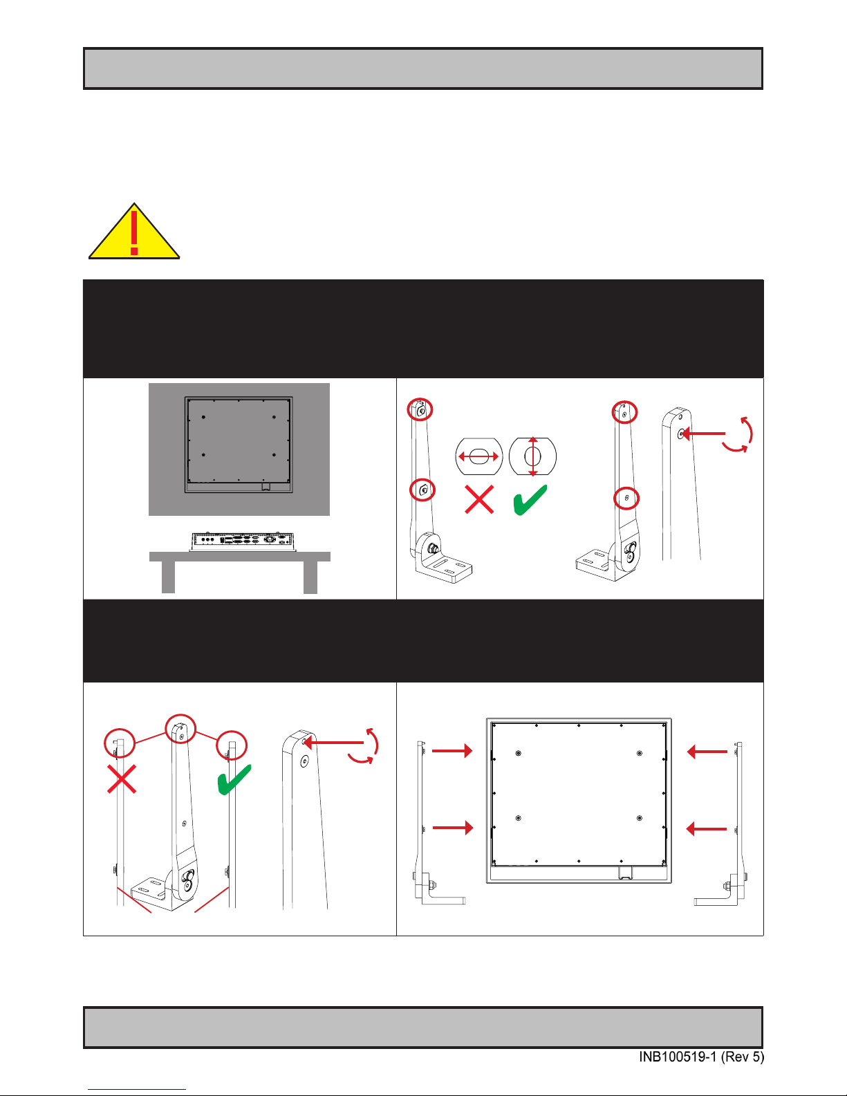
Panel / Console Mounting Key Hole Bracket Kit for 12”,15”,17”,19”
You need: Allen Wrench tool (3mm), 4 pcs of HD CMB SX1-A1 kit (included in delivery).
Procedure suitable for: Display and Panel Computers Series X range.
Attention: A suitable pre-cut panel cutout should be made prior to mounting. Do not force the
unit into the panel cutout as it might break the outer glass or scratch the chassis on the unit. Make
sure that the panel cutout is not too tight for the unit. Please disconnect ALL cables before
proceeding. Please re-check the relevant and required panel cutout measurements if unsure.
1: Slide the unit into the cutout carefully. User Controls
and Connector Area should be facing downwards.
2: Prepare and position the brackets into each of the four
key holes. The key part goes into the unit’s largest area
of the keyhole, while the Allen screw is visible at the top.
See closeup.
3: When all brackets ts inside the keyhole, slide them down into the narrow gap. If you are unable to slide them
down, simply adjust/loosen the top Allen Screw slightly and try again.
4: Secure the unit by fastening the top Allen screws fairly. Make sure you do it equally and even for all 4 sides. Do
not use excessive force. See closeup of a open and closed position to the right.
Open Closed
Page 17
17
Installation
IND100078-32
Installation Procedures
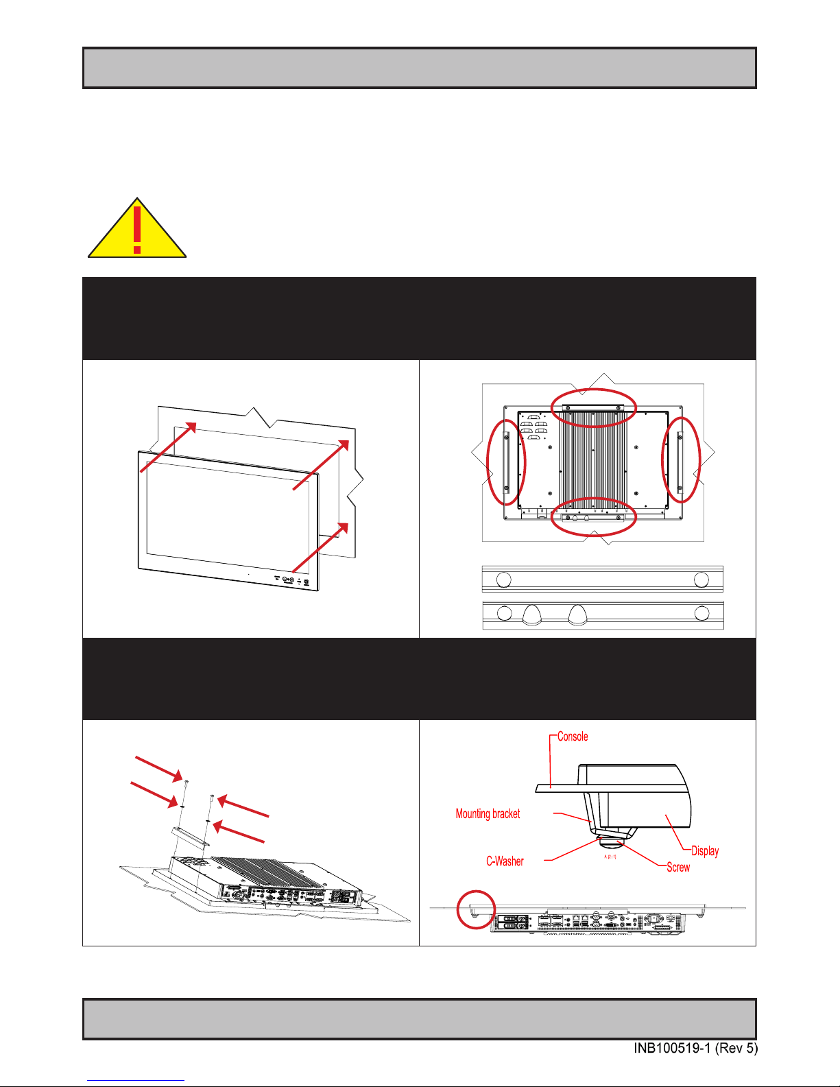
Panel Cutout / Console Mounting Bracket Kit for 24”,26”
You need: Pozidriv tool, 1 pcs of HD CMB SX1-B1 kit (included in delivery).
Procedure suitable for: Display and Panel Computers Series X range. 24 inch used as illustration below, but same
procedure also valid for 26 inch models.
Attention: A suitable pre-cut panel cutout should be made prior to mounting. Do not force the
unit into the panel cutout as it might break the outer glass or scratch the chassis on the unit. Make
sure that the panel cutout is not too tight for the unit. Please disconnect ALL cables before
proceeding. Please re-check the relevant and required panel cutout measurements if unsure.
1: Slide the unit into the cutout carefully. User Controls
and Connector Area should be facing downwards.
2: Make sure you are aware that brackets should be
mounted on TOP, LEFT, RIGHT and BOTTOM sides.
Note that the [B] bracket is different than the [A]
brackets and mounted near the connectors. See closeup
of details.
[A]
[B]
[A]
[A]
[A]
[B]
3: Secure each bracket with the provided M5x16 screws
and C-Washers as illustrated below. Make sure you do
it equally and even for all 4 sides. Do not use
excessive force. 2 screws and 2 washers pr. bracket.
Note the orientation of brackets before you begin.
4: Review closeup of the mounting of brackets with
screws and C-Washers in place. Seen from bottom side.
Washer
Washer
Screw
Screw
Page 18
18
Installation
IND100078-34
Installation Procedures
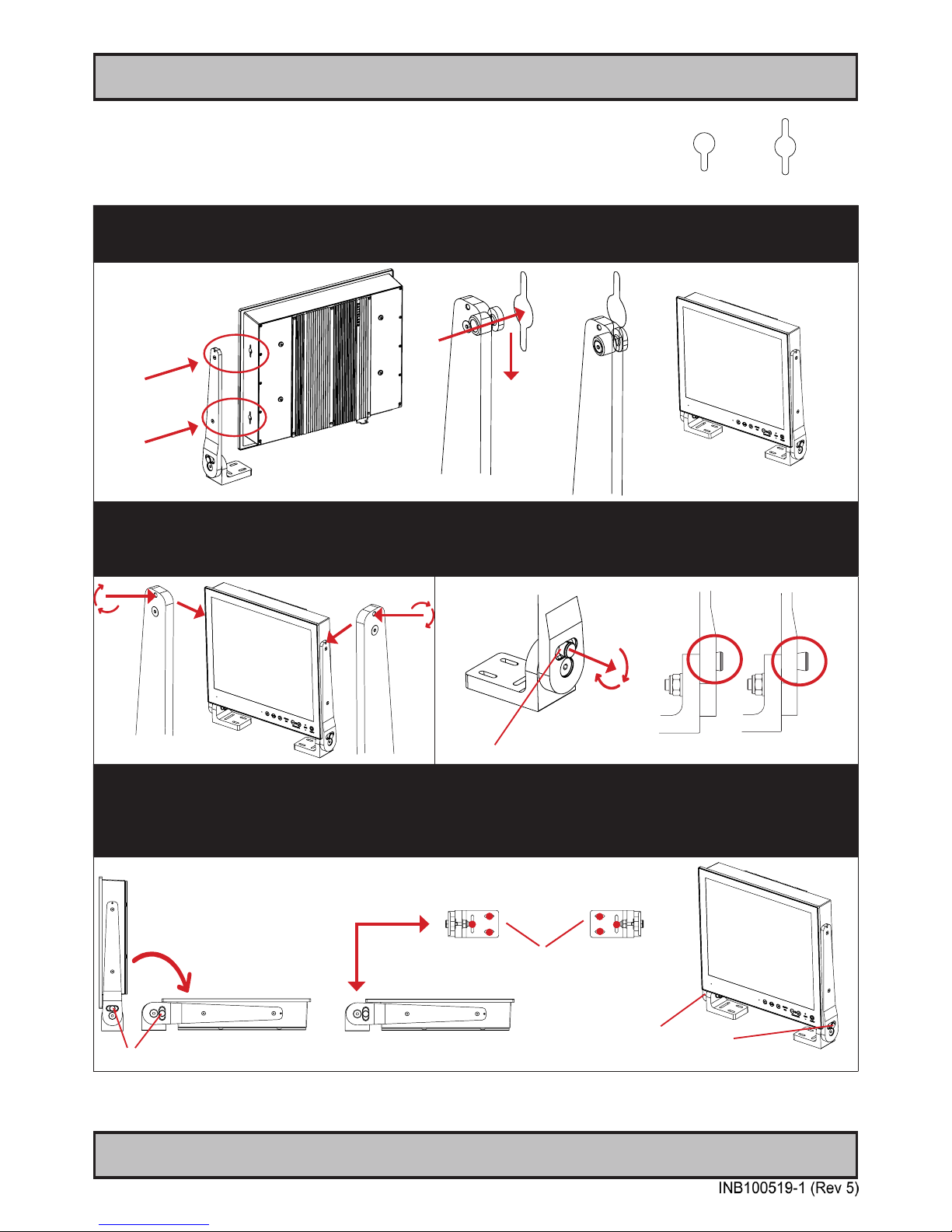
Mounting Bracket for Table / Desktop installation - 12”,15”,17”,19”
You need: M4, M5, M10 Unbrako® Hex Key tool, M10 Wrench and 1 pcs of HD xxBRD SX1-A1 Mounting Bracket Kit,
where xx=12, 15, 17 or 19 inch. Fasteners (6 pcs M6) for Table / Desktop location not included.
Procedure suitable for: Display and Panel Computers Series X range.
Attention: A suitable pre-drilled location and knowledge of measurements for both main unit and
brackets/tilting functionality should be prepared and checked prior to mounting. Please disconnect
ALL cables before proceeding. Please review User Manual or visit www.hatteland-display.com for
Technical Drawings regarding measurements for both main unit and Mounting Brackets.
1: Place the unit on a dry, at, clean, soft surface
(i.e. table) with the glass front facing down as
illustrated. Connector area should be facing
downwards from you.
2: Inspect the inner side of both brackets and especially the
orientation of the Key Hole Plug (4 pcs). They should be
shaped as an standing “egg” to ensure proper tting in the
Key Hole of unit (FIG1). Note: You may have to loose the
fastening screw (M5) (FIG2) if the Key Hole Plug can not be
turned by hand.
Seen from
above
Connector Area
Wrong Correct
Adjust
FIG2
FIG1
3: Verify that the Key Hole Set Screw (M4) is aligned
with the bracket surface (FIG1). If this screw appear
too far out (FIG2), proper tting into the Key Hole
can not be completed. Turn screw clockwise or anticlockwise (FIG3) to adjust the position.
4: Notice the indication of LEFT and RIGHT. The mounting
bracket (2 pcs) is marked with respective stickers (L/R) from
factory. Please make sure that LEFT bracket is positioned on
LEFT side and RIGHT bracket is positioned on the RIGHT
side as shown below.
Wrong Correct
Adjust
FIG1 FIG3FIG2
Bracket Surface
LEFT RIGHT
Page 19
19
Installation Procedures
Installation
IND100078-34
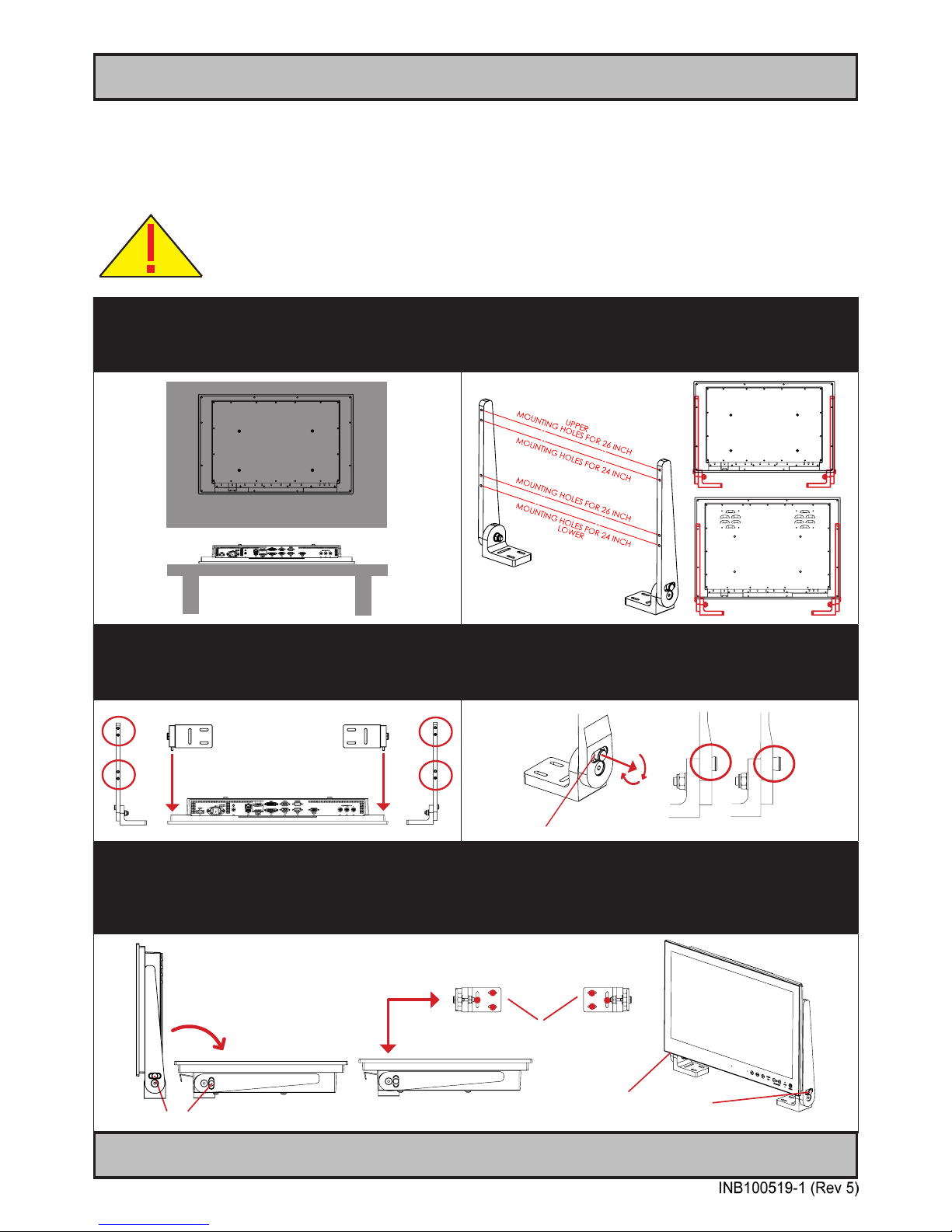
Note: Some units may have Single Key Hole, whilst others have Double Key Hole.
2012 2012 / 2013
This is due to slight variation in initial production vs Mass Production throughout
2012. During early 2013, all units will have Double Key Hole.
5: Ensure that both Key Hole Plugs slide into the Key Holes and goes to the bottom position (FIG1 and FIG2). If they
appear too tight, you may loose the Key Hole Plug screw a few turns and re-try (see previous step 2). FIG3 shows
Key Hole Plug correctly into Key Hole and both brackets in place.
FIG1
FIG2
FIG3
FIG3
6: Tighten Key Hole Screw rmly on each side and
make sure the brackets are properly mounted and
aligned to the main chassis of unit. Verify with your
hands that both brackets are rmly attached.
7: While unit is lying at on table, check the Tilting Lock Pin
position. These can be pulled out by hand, turned 90° (FIG1)
and turned back 90° until the Lock Pin automatically clicks into
place by a spring (FIG2).
FIG1
FIG2
Locked Unlocked
8: You may now mount the unit onto your desired location. It is advised that you unlock the Lock Pin (as shown in
step 7), tilt the unit 90 degrees backwards (FIG1) and properly fasten the bracket base into location (FIG2).
NB! Be careful not to break or scratch the edge of the front glass! Then repeat step 7 again until your desired
tilting position has been achieved and you have veried that the Lock Pin are in locking position and the unit is rmly
attached and does not appear loose (FIG3).
Unlock, tilt and lock
FIG1
FIG2
Top View
Use appropriate fasteners
6 pcs x M6 needed
FIG3
Re-check Lock Pins!
Page 20
20
Installation
IND100078-33
Installation Procedures
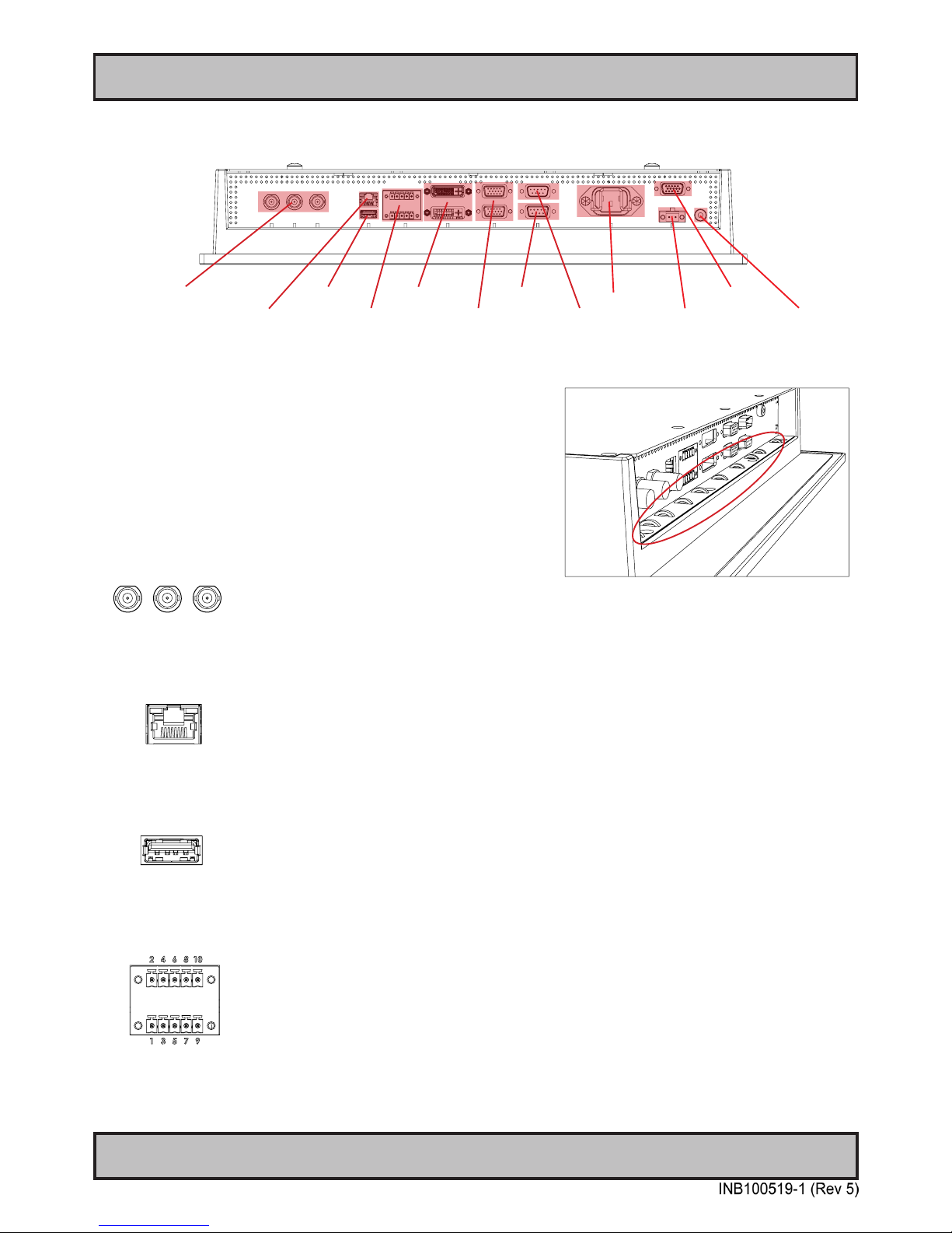
Mounting Bracket for Table / Desktop installation - 24”,26”
You need: M5, M10 Unbrako® Hex Key tool, M10 Wrench and 1 pcs of HD TMB SX1-C1 Mounting Bracket Kit.
Fasteners (6 pcs M6) for Table / Desktop location not included. Procedure suitable for: Display and Panel Computers.
Attention: A suitable pre-drilled location and knowledge of measurements for both main unit and
brackets/tilting functionality should be prepared and checked prior to mounting. Please disconnect
ALL cables before proceeding. Please review User Manual or visit www.hatteland-display.com for
Technical Drawings regarding measurements for both main unit and Mounting Brackets.
1: Place the unit on a dry, at, clean, soft surface (i.e.
table) with the glass front facing down as illustrated.
Connector area should be facing downwards from you.
2: Inspect the mounting holes of brackets. For mounting to
a 24 inch unit, please use the lower holes as indicated.
For mounting to a 26 inch unit, please use the upper holes
as indicated.
Seen from
above
Connector Area
24 inch
26 inch
3: Place one bracket at the time with the mounting
holes facing down into the suitable mounting position
and fasten with 2 x M5 screws on each bracket.
4: While unit is lying at on table, check the Tilting Lock
Pin position. These can be pulled out by hand, turned 90°
(FIG1) and turned back 90° until the Lock Pin automatically
clicks into place by a spring (FIG2).
FIG1
FIG2
FIG2
FIG1
FIG2
Locked Unlocked
5: You may now mount the unit onto your desired location. It is advised that you unlock the Lock Pin (as shown in
step 4), tilt the unit 90° backwards (FIG1) and properly fasten the bracket base into location (FIG2).
NB! Be careful not to break or scratch the edge of the front glass! Then repeat step 4 again until your desired
tilting position has been achieved and you have veried that the Lock Pin are in locking position and the unit is rmly
attached and does not appear loose (FIG3).
Unlock, tilt and lock
FIG1
FIG2
Top View
Use appropriate fasteners
6 pcs x M6 needed
FIG3
Re-check Lock Pins!
Page 21
21
IND100133-48
Connection area of unit (illustration)
Physical Connections
Reduce Cable Tension
To reduce tension of the cables you connect, secure them with
a cable tie to the available chassis hinges located near the
connectors.
Note: Amount of chassis hinges can vary depending on model.
Grounding Screw
3 x BNC, Composite Video IN
Power Input DC
USB Touch
RJ45 Network 2 x VGA/RGB InRS-422/RS-485 COM
RS-232 COM
Potmeter Port
2 x DVI-D In
COMPOSITE VIDEO IN 1,2,3:
Connect a Composite Video signal (PAL/NTSC/SECAM) to any of these 3 x BNC female connectors to allow video
feed to be used as Full Screen, Picture-In-Picture (PIP) or Picture-By-Picture (PBP) from i.e. cameras & DVD players
in addition to the regular DVI or RGB/VGA signal input.
Network/LAN INPUT / OUTPUT (NET A):
Supports 10/100/1000Mbps Ethernet (LAN). Suitable for twisted pair cables CAT.5E. Make sure the network cable
connector ”clicks” into the RJ-45 connector. This connector will allow remote control of the display unit to control
common functions like brightness, input source and more.
USB TOUCH:
Connect a TYPE A USB Cable between this connector and your PC. Suitable drivers to install and calibrate the
touchscreen are available on the separate installation media delivered with the unit. USB1.1 is suitable for cable
distances above 10meter/32.8 feet, whereas USB2.0 is suitable from less than 10meter/32.8 feet distances.
RS-422 / RS-485 COM I/O:
The COM (non-isolated RS-422/485) allows functionality to communicate with serial based equipment including
external buzzer functionality. Connect and fasten your cables from your compatible external equipment to the Phoenix
Terminal (3.81) connector block. Please review the “Pinout Assignments” chapter in this manual for more information.
Note: 19 inch unit used as example above, please review specications for your actual model.
VGA/RGB Out
Power Input AC
Page 22
Physical Connections
22
IND100133-48
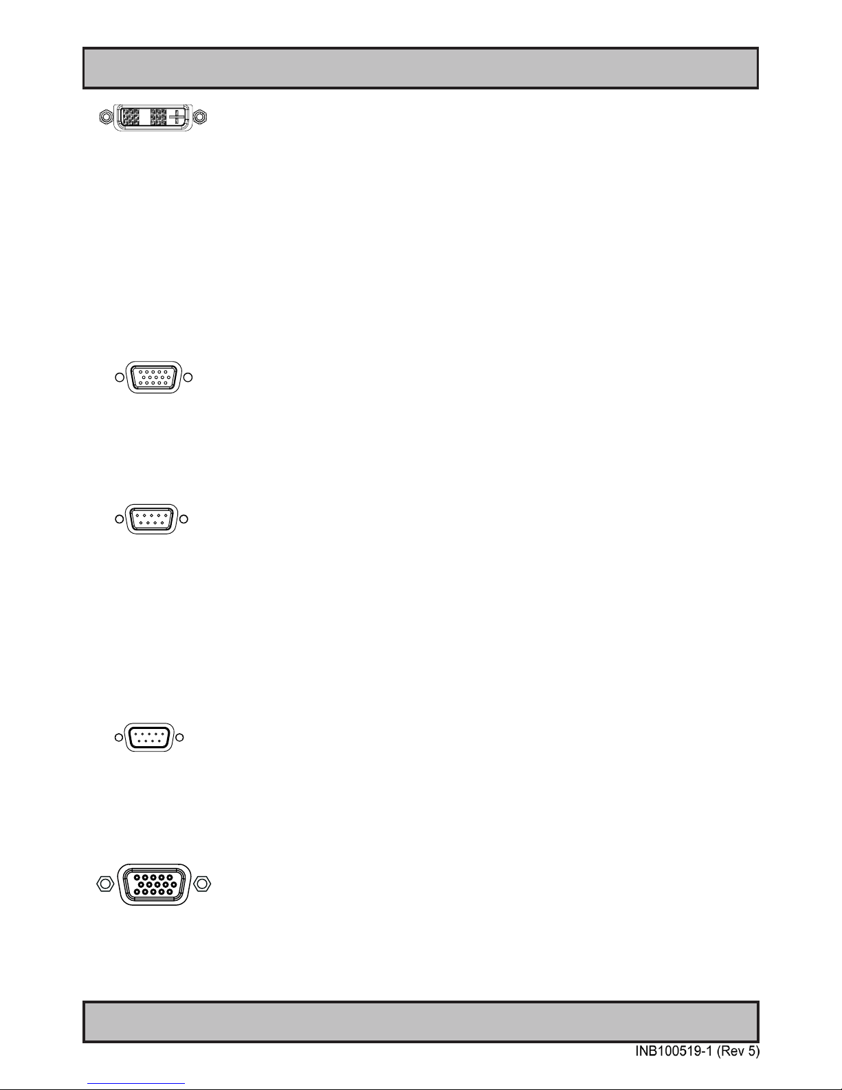
DVI-D IN:
Connect your DVI cable to any of the two DVI-D 18+1P, Single Link Connector (female). Secure your DVI cable to the
hex spacers provided on the unit and make sure you do not bend any of the pins inside the connector. Connect the
other end of the cable to the DVI connector on your equipment and secure it.
Important note for DVI signal detection:
Please note that for the operating system to detect DVI signals correctly, the DVI cable MUST be connected physically
to the unit during boot up otherwise you may experience a black image. Furthermore certain graphics drivers may
need to refresh their device list (often done manually by user - detect devices), while in some cases the Plug-n-Play
will automatically detect the DVI signal correctly. Please consult your local technician if you have this behaviour of
detection problems when using DVI. In all cases the problem can be solved in the operating system, and this is not a
malfunction in the graphic controller for display units.
VGA/RGB IN:
Connect your VGA cable to any of the two D-SUB 15P Connectors (female). Secure the VGA cable to the hex spacers
provided on the unit and make sure you do not bend any of the pins inside the connector when connecting. Connect
the other end of the cable to the VGA connector on your equipment and secure it.
RS-232 COM I/O:
This 9P COM connector provides additional functionality for the unit. The Serial Remote Control features a RS-232
(non-isolanted) interface for controlling internal parameters like brightness. You can access most of the parameters
available in the OSD menu and with special commands control the unit externally. This COM can also be used to
upgrade the rmware for the graphic controller inside the unit which is available on request and through service
channels (for qualied personnell only). Fasten your external cable to the D-SUB 9P Male connector using the
provided screws on the cable housing.
Please review “Management Settings/Communication” in the “OSD Menu Functions” chapter for more information.
POTMETER INPUT / OUTPUT:
Allows for controlling Brightness of the displayed image on screen by connecting an external remote control to the
9P D-SUB (male) connector which has Potentiometer IN, +5VDC OUT and BRT +/- IN functionality built in. Review
also the “Pin Assignments” chapter in this manual for more information.
VGA/RGB OUT:
VGA/RGB OUT enables a direct clone of the incoming VGA (RGB1) signal. Connect the cable to the D-SUB 15P
Connector (female) and secure it to the hex spacers provided on the unit. Connect the other end to your equipment
and secure it. Note that DVI inputs is NOT cloned, even though if the DVI-I connector has been configured with the
DVI-I > RGB adapter to use a RGB signal as input.
Page 23
Physical Connections
23
IND100133-48
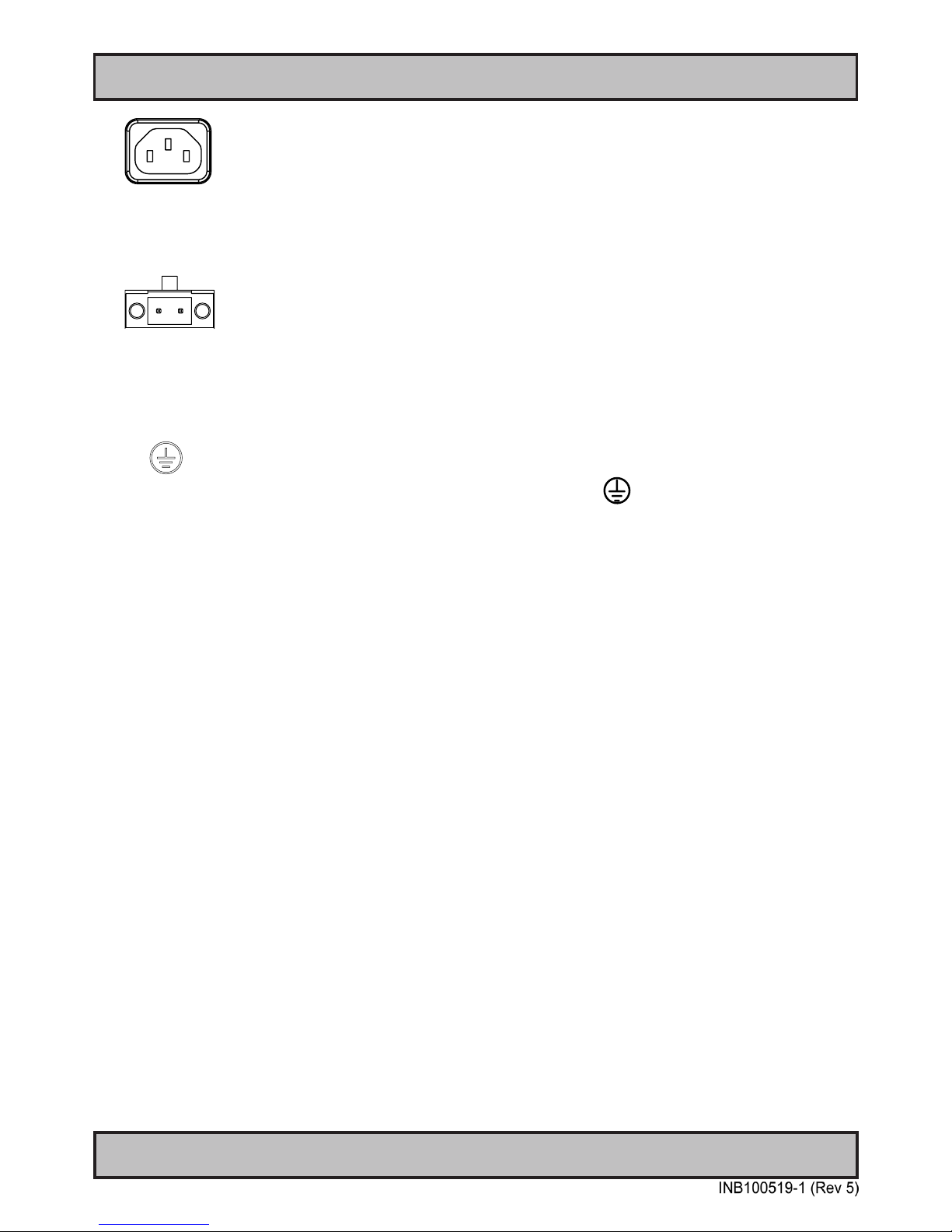
POWER INPUT:
The internal AC power module supports both 115VAC/60Hz and 230VAC/50Hz power input. Please check
specifications for your unit.
- +
POWER INPUT:
Connect your DC power cable to the Phoenix 2pin 1927564 MSTB 2,5/2-GF-5,08 THT connector. The internal DC
power module supports 24VDC. Please check specifications for your unit.
GROUNDING SCREW:
Note: DC models are required / recommended to be properly grounded via the screw located on the unit. Please
review “General Installation Chapter”, pt. 6 for more information.
Multi-power note: (For units supporting AC & DC input simultaneously)
The unit has a dual input power supply which will accept both AC and DC input. If both inputs are connected, the
unit will be powered by AC. If AC is disconnected it will automatically switch over to DC without affecting the operation
of the unit. This makes it possible to use AC power as primary power and a 24V battery as secondary power,
eliminating the need for expensive UPS systems.
Page 24
24
This page left intentionally blank
Page 25
25
Operation
Page 26
26
IND100064-40
Operation
User Controls
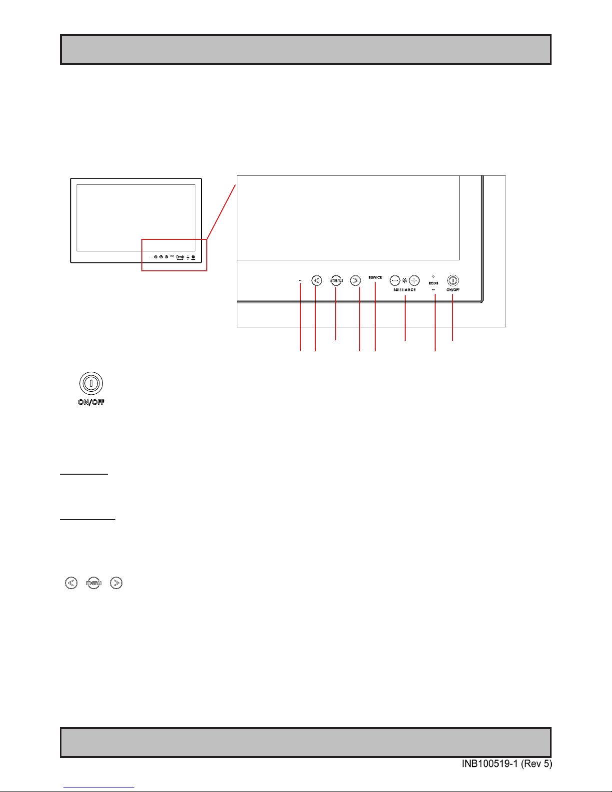
OSD Menu Brightness Power On/Off + Status
Light Sensor - Navigation - Action Indicators ECDIS Status / Indicator
Power ON/OFF:
This symbol and all text will illuminate in red when suitable power is connected and the unit is turned off. When the
unit is on and operating, this symbol will illuminate constantly either in yellow color (signal not recognized/not present
and no image on screen) or green color (signal detected and image on screen).
Power ON:
To turn the unit on, verify that the symbol is illuminated in red (indicates suitable power is connected) and touch the
power symbol and hold until the the symbol changes to green light/yellow light or a image appears on the screen.
Power OFF:
To turn the unit off, touch the power symbol and hold until it either illuminate/change from green/yellow to red or the
image on screen disappears.
OSD Menu, Navigation and Hotkeys:
The “<” and “>” symbols has two functionalites. If the OSD (On Screen Display) menu was activated (and is cleary
visible on screen), both the “<” and “>” are used to navigate and set options within the OSD menu. If the OSD menu
is not activated (no OSD visible on screen), both the “<” and “> symbols function as hotkeys. To use the dened
hotkeys assigned, touch the “<” or “>” symbols. The hotkey functionality can be changed or disabled by accessing the
main On Screen Display (OSD) menu and the appropriate menu function. With Hotkey functionality you can dene
options from the OSD menu for easier control and everyday usage of the display unit.
To access the main OSD menu, touch anywhere on the “MENU” circle symbol and the OSD menu will clearly be seen
as an overlay over the existing displayed image. The complete denition of all the menus and functions are available
in the “OSD MENU FUNCTIONS” chapter in this manual.
USER CONTROLS OVERVIEW
The units are designed by using Glass Display Control™ (GDC) touch technology to allow interactivity adjusting
brilliance (brightness) and control power on / off with the use of illuminated symbols. Note that these symbols are
only visible (backlight illuminated) when suitable power is connected. There is no physical moving knobs, potmeters,
wheels or push buttons available as everything is touch surface controlled by Projected Capacitive
technology, that allows a human nger (including several types of gloves) to control the unit.
Page 27
27
Operation
User Controls
IND100064-40
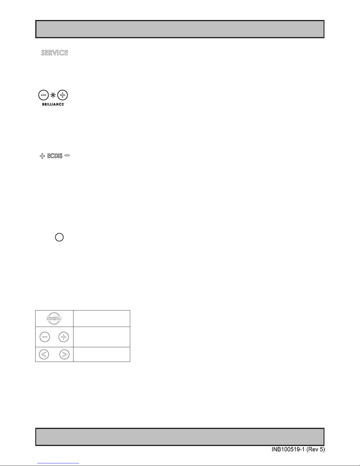
Action Indicators:
SERVICE = Built in functionality to determine when the unit requires service in order to perform within preset
factory standards. This area will illuminate constantly until the unit is powered off.
Note that by touching this symbol no action will be performed or has been assigned.
Brightness Adjust:
Brilliance / Brightness adjustment of the displayed image is adjusted by touching the (-) or (+) illuminated symbols.
The entire area of text and symbols are visible as long as the unit is powered. Note that only the (-) and (+) are touch
sensitive while the “*” and “BRILLIANCE” symbols are not. The symbols (-) and (+) are also used to change values in
the OSD menu when its activated / function selected for adjusting.
ECDIS Status / Indicator: (optional factory standard)
For units that has been factory ECDIS calibrated the text “ECDIS” will illuminate in green constantly as long as the
unit is powered. The “+” and “-” symbols will illuminate in red when the Brightness/Brillance is adjusted either above or
below ECDIS factory calibration point.
To be able to stay within ECDIS calibrated range, please assure that both the “+” and “-” are not illuminated and that
“ECDIS” text remains illuminated during operation. Note that by touching these symbols no action will be performed or
has been assigned.
Note: ECDIS functionality is only suitable for models above 15 inch.
Light Sensor:
Used to sense level of ambient light in the surrounding environment. The sensor data can be read by suitable software
through the Hatteland Display SCOM functionality of the unit and thus can be used to control brightness remotely.
Note: This sensor is not visible for the eye or has any illumination behind to indicate it’s position. Further, by touching
or covering this area will naturally make the sensor data inaccurate.
Note:
In the following “On Screen Display (OSD)” menu chapter, these buttons are referenced as:
“MENU”
“(-) Brilliance (+)”
“(<) Navigation (>)”
Page 28
28
User Controls
IND100064-39
OSD Menu Overview
On Screen Display (OSD) Menu Introduction
The OSD menu consists of main menus and submenus which is very easy to navigate through. All functions are
explained in-depth later in this user manual. You should prior to using the OSD menu and functions, be sure to
familiarize yourself with how to physically access the menu, how to navigate up/down/left/right, how to modify values,
exiting menus and more.
Please note: Factory default illustrations only! Available functions, icons and text may deviate slightly from actual OSD menu on
your product due to different OSD software congurations and customized solutions.
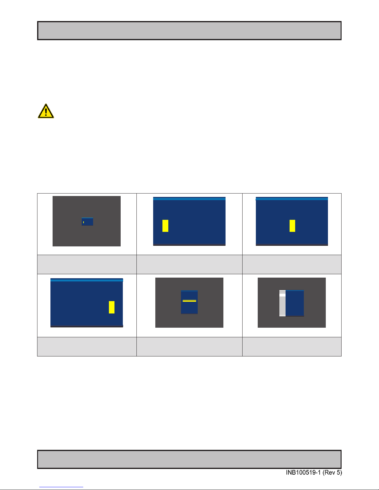
OSD Keycode / OSD Lock Mode
During use, a small requester may pop-up on screen asking you for a “Key Code”. This is a safety feature (due to
ECDIS Compliance) that might be predened in your setup. To quickly understand how to enter a code, navigate and
nally access the underlying main menu, simply follow the illustration below. The “Key Code” is by factory default
“321”. If the “Key Code” requester do not appear on screen, you can skip reading this section for now and proceed to
the next page.
►
0 0 0
►
►
►
►
►
Please enter key code
to access menu
Active Display Area + Requester
►
0 0 0
►
►
►
►
►
Please enter key code
to access menu
Close-up of Requester
►
3 0 0
►
►
►
►
►
Please enter key code
to access menu
Close-up of Requester
1: Typical position of requester on screen.
Yellow box indicate number position, default
loaction is always on rst number.
2: Enter rst number (from 0 to 9).
Use “Navigation/Hot Keys” touch buttons to
increase/decrease. Number change in real time.
3: Now touch menu button to store rst
number and proceed to second number.
Yellow bar will move its position too.
►
3 2 1
►
►
►
►
►
Please enter key code
to access menu
Close-up of Requester
Exit
Input Source Settings
Image Settings
Color Mode Settings
Multi-PIP Settings
OSD Misc
Management Settings
Service
Simplied
Active Display Area + OSD Menu
Exit
Main Source
Analog VGA 2
Secondary Source CVBS 2
Auto Source
Disable
Input Source Settings
Exit Menu
Input Source
Settings
Image
Settings
Color Mode
Settings
Multi-PIP
Settings
OSD
Miscellaneous
Management
Settings
Service
Settings
►
►
►
►
Active Display Area + OSD Menu
4: Repeat step 2 and 3, until
“Key Code” reads “3 2 1” and nally touch
menu button to continue.
5: The OSD menu appear in “Simplied” mode
(if confgured to do so)
6: The OSD menu appear in “Full” mode
(if confgured to do so)
After the code was successfully entered you will gain access to the OSD Menu and a multitude of functions will be
available for adjusting or reviewing. Please proceed to the next page, where you will learn the differences between
“Simplied” and “Full” menu modes and a complete map of all the underlying functions available within.
Page 29
29
User Controls
OSD Menu Overview
IND100064-39
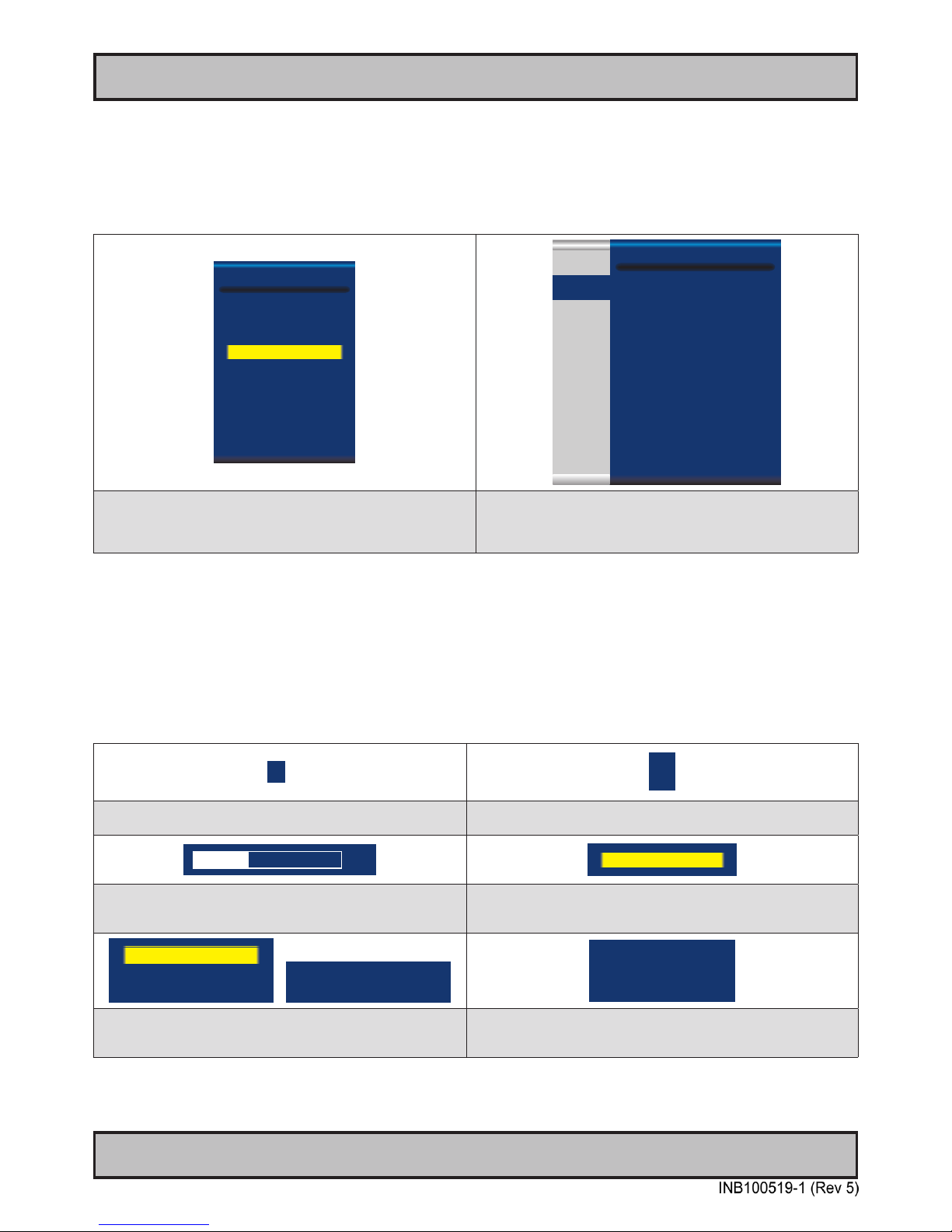
OSD Simplied and Full Menu modes (examples)
You may encounter two different menu size setups based on factory default or by customized preset conguration.
The Simplied Menu mode offers easy and clear access to most commonly used functions. The Full Menu mode
offers a more advanced menu with technical information and is suited for more technical minded users.
Exit
Input Source Settings
Image Settings
Color Mode Settings
Multi-PIP Settings
OSD Settings
Management Settings
Service
Simplied
Exit
Main Source:
Digital 1
Second Source:
Composite 1
Auto Source Select Enable
Rename Source Digital 1
Input Source Settings
Exit Menu
Input Source
Settings
Image
Settings
Color Mode
Settings
Multi-PIP
Settings
OSD
Settings
Management
Settings
Service
Settings
►
►
►
►
►
►
Simplied OSD Menu showing for example “Color Mode Settings”
chosen in the menu. Each of these lines might have additional
submenus where other lists of choices will be seen. The design
and size of OSD menu area does not change.
Full OSD Menu showing for example “Input Source Settings”
chosen in the menu. The left menu bar is visible at all times, while the
right section will change based on contents of that submenu.
The design and size of OSD menu area does not change.
OSD Visual Feedback (examples)
Throughout all OSD menus there are certain symbols you need to familiarize yourself with. These are to visually
indicate that a value can be increased/decreased, accessed, display a Slide Bar Meter or just for information purposes
only. All functions with arrows have text based, human readable lists with a start and end choices. A Slider Bar with
number beside it will indicate the value has a minimum, current and max limit. All changes in values and lists happen
in real time as you touch the menu button and/or touch navigation buttons.
►
►
►
Arrow pointing right means that there is an submenu available for this
function for further adjustments and functions.
Arrow pointing up/down means that the current choice can be changed
in-place from a list that has a start and end.
34
Color Mode Settings
Slider Bar meter indicates the “lling” up based on a minimum and
maximum value. The current value is written to the left.
Whenever a function is selected, the item will be visually indicated
with a yellow bar behind it. The other choices available will be in white
text with no yellow bar behind.
Norsk
English
Francais
Analog RGB1
PIP Mode OFF
PIP Display
SWAP
Functions displayed in Green Color indicates either the current stored
value of the function and sometimes to draw user’s attention towards
information about an selected function or its current state.
Functions displayed in gray text means that set of functions may
depend on a different option to be turned on or congured rst. In this
example, “PIP” functions are all unaccessible, since “PIP Mode” is “OFF”.
Note: The examples above are the most common ones displayed. Your menu may have slight different style and colors, depending on rmware,
variations and customized solutions, but the logic of operation is the same.
Page 30
30
User Controls
OSD Menu Overview
IND100064-39
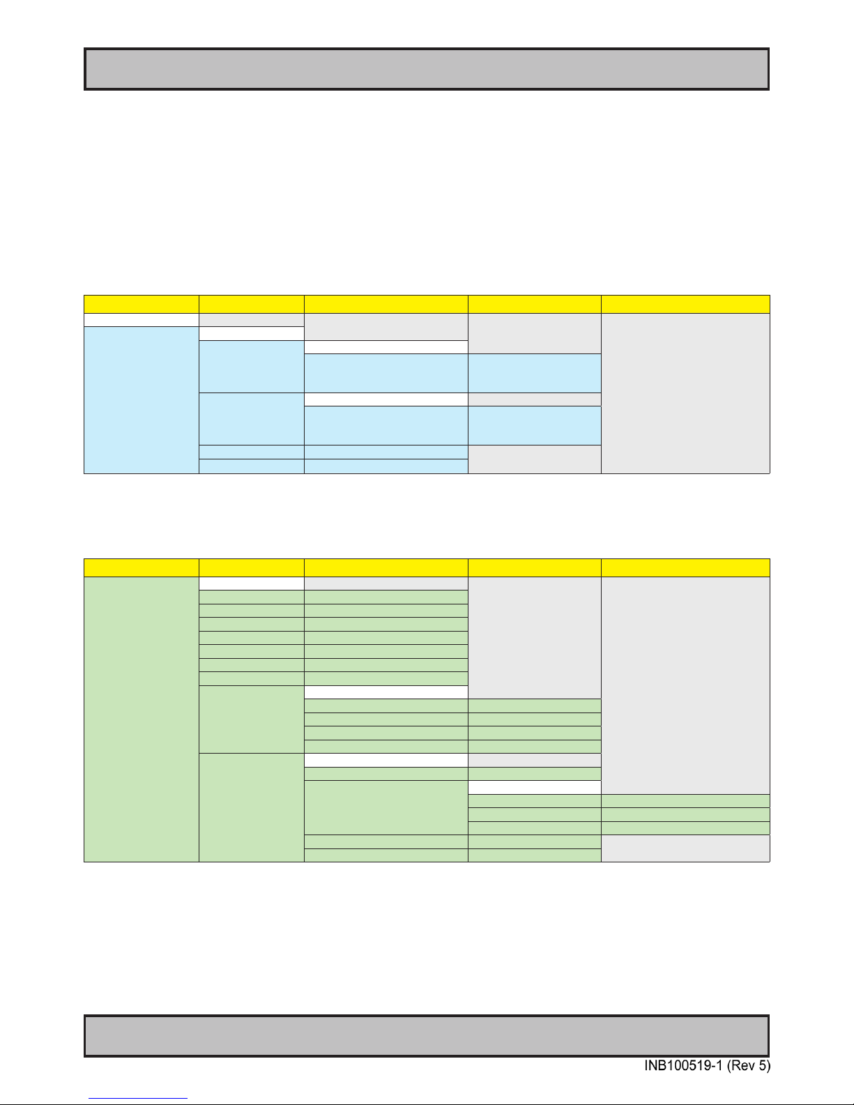
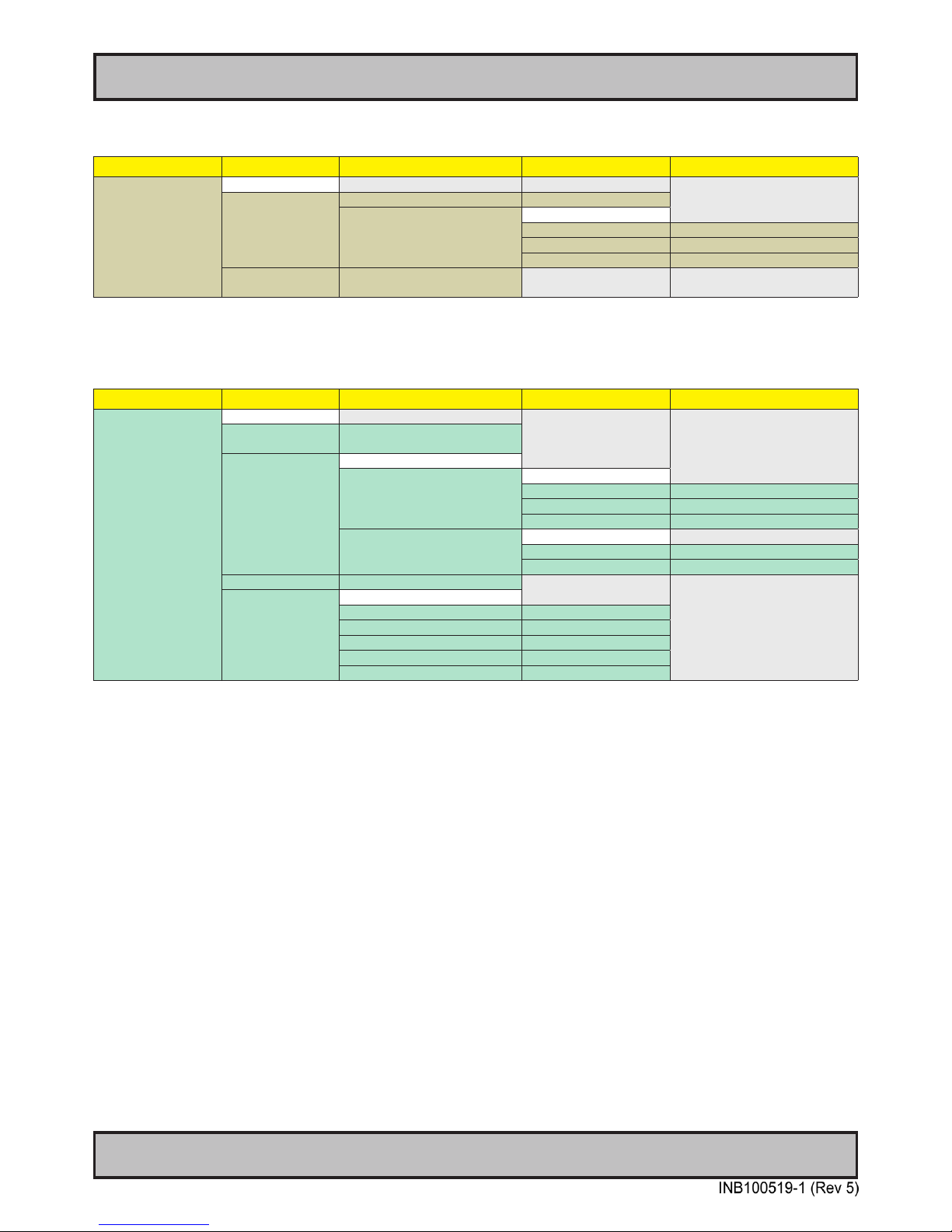
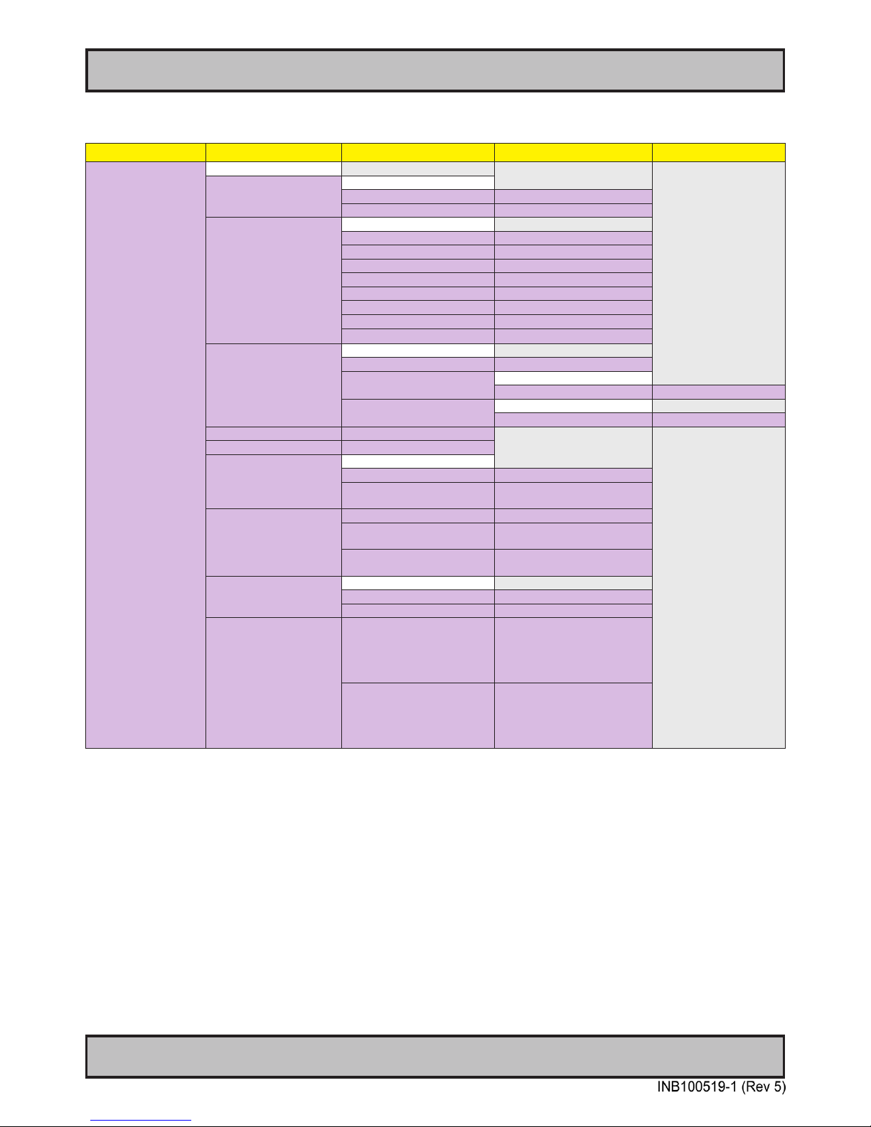
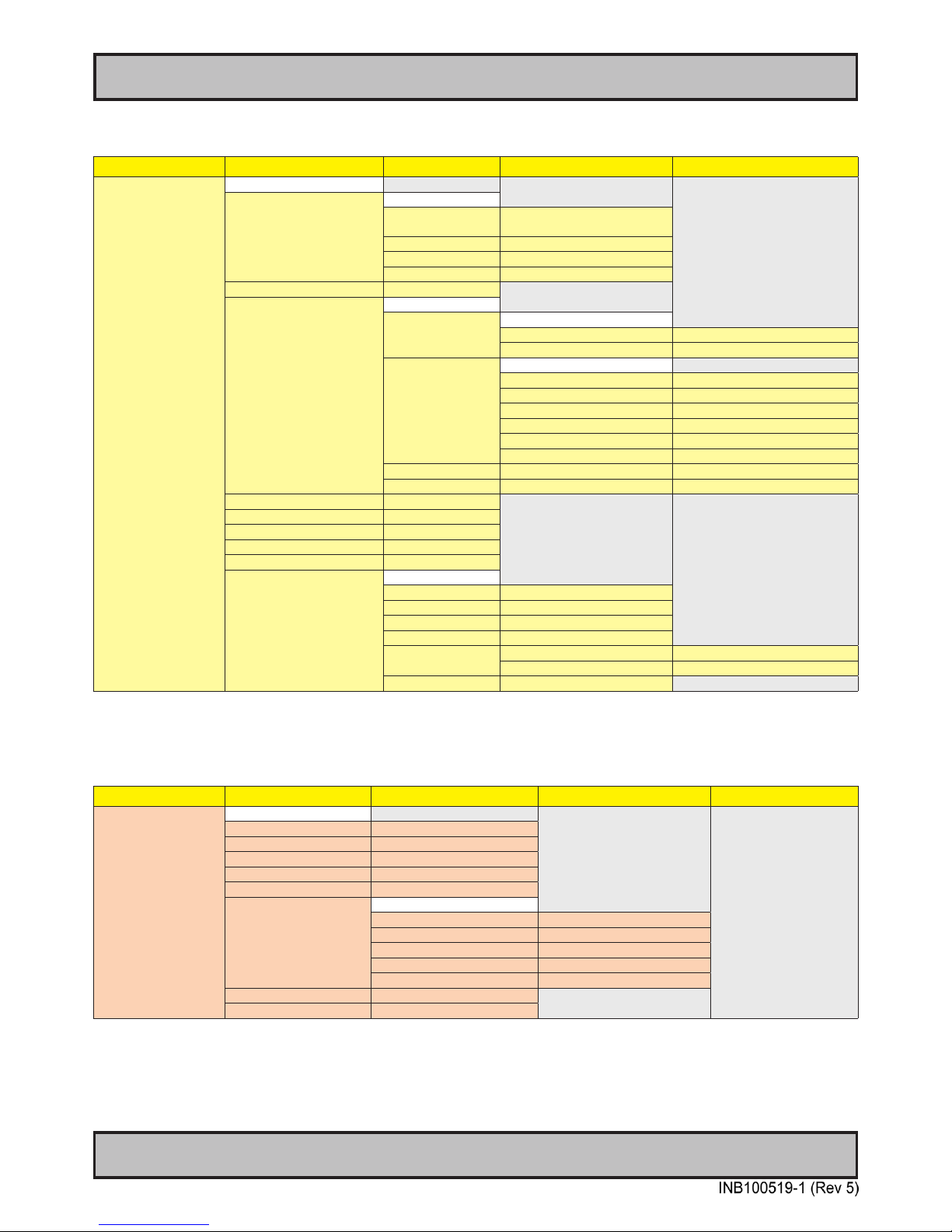
OSD Menu Structure
In this table all functions within menus and their submenus are shown. Functions that begins with an asterix (*) and in
bold/red font color style indicates this function/menu is only available during “Full” menu mode or during Video CVBS
fullscreen. Functions with a “>” in the end, indicates a submenu or list of options will be displayed. Depth of the sub-
menus (levels) are identied from 1 to 5.
Input Source Settings (page 30-31)
Level 1 (Main Menu) Level 2 Level 3 Level 4 Level 5
Exit
Input Source Settings > < Exit
Main Source > < Exit
Digital 1, Digital 2, Analog RGB1,
Analog RGB2, Composite 1,
Composite 2, Composite 3
(Text Displayed)
Second Source > < Exit
Digital 1, Digital 2, Analog RGB1,
Analog RGB2, Composite 1,
Composite 2, Composite 3
(Text Displayed)
Auto Source Select > Enable, Disable
Rename Source > <On Screen Keyboard Input>
Image Settings (page 32-36)
Level 1 (Main Menu) Level 2 Level 3 Level 4 Level 5
Image Settings > < Exit
Auto Position > (Automatic Action)
Auto Color Balance > (Automatic Action)
*Brightness > (Slider Bar)
*Contrast > (Slider Bar)
*Saturation > (Slider Bar)
*Hue > (Slider Bar)
Sharpness > (Slider Bar)
Display > < Exit
Horiz Position > (Slider Bar)
Vertical Position > (Slider Bar)
Clock > (Slider Bar)
Phase > (Slider Bar)
*Video Setup > < Exit
Main MADI Mode > Normal, Adaptive, Off
Noise Reduction > < Exit
Dynamic NR Mode > High, Medium, Low, Adaptive, Off
MPEG NR Mode > On, Off
Sharpness Noise Coring > High, Medium, Low, Adaptive, Off
Film Mode > 2:2, 3:2, 3:2-2:2, Off
DCDi > On, Off
Page 31
31
User Controls
OSD Menu Overview
IND100064-39
Color Mode Settings (page 37)
Level 1 (Main Menu) Level 2 Level 3 Level 4 Level 5
Color Mode Settings > < Exit
Color Temperature > 9300K, 8000K, 6500K > (Automatic Action)
User > < Exit
Red > (Slider Bar)
Green > (Slider Bar)
Blue > (Slider Bar)
*Gamma > No Calibration, Calibration VGA,
Calibration DVI
Multi-PIP Settings (page 38-39)
Level 1 (Main Menu) Level 2 Level 3 Level 4 Level 5
Multi-PIP Settings > < Exit
PIP Mode > PIP Off, PIP Child, PIP Split,
PIP Wide.
PIP Display > < Exit
PIP Child Size > < Exit
PIP Size > (Slider Bar)
PIP H-Size > (Slider Bar)
PIP V-Size > (Slider Bar)
PIP Position > < Exit
PIP H-Position > (Slider Bar)
PIP V-Position > (Slider Bar)
Swap Source > (Automatic Action)
PIP Picture > < Exit
Brightness > (Slider Bar)
Contrast > (Slider Bar)
Saturation > (Slider Bar)
Hue > (Slider Bar)
Sharpness > (Slider Bar)
Page 32
32
User Controls
OSD Menu Overview
IND100064-39
OSD Settings (page 40-43)
Level 1 (Main Menu) Level 2 Level 3 Level 4 Level 5
OSD Settings > < Exit
OSD Position > < Exit
OSD H Position > (Slider Bar)
OSD V Position > (Slider Bar)
Language > < Exit
Norsk > (Select for Norwegian)
English > (Select for English)
Français > (Select for French)
Deutsch > (Select for German)
Italiano > (Select for Italian)
Español > (Select for Spanish)
日本語 >
(Select for Japanese)
簡體中文 >
(Select for Simplied Chinese)
Presets > < Exit
Recall > (Automatic Action)
Save > < Exit
User 1 to 5 > (Automatic Action)
Load > < Exit
User 1 to 5 > (Automatic Action)
OSD Timeout (Sec) > (Slider Bar)
OSD Transparent > (Slider Bar)
OSD Mode > < Exit
Simplied > (Select)
Full > (Select) and
Enter Key Code “362”
OSD Lock Mode > Normal Mode > (Select)
Password Protect > (Select) and
Enter Key Code “321”
Full Mode > (Select) and
Enter Key Code “321”
OSD Key Outdoor > < Exit
On > (Select)
Off > (Select)
Hot Key Assignment > Key 1 > Black Level, PIP Size, Main
Source, Second Source, PIP
Mode, Scaling, Swap Source,
Test Pattern, LED Drive,
Language, No Function
Key 2 > Black Level, PIP Size, Main
Source, Secondary Source, PIP
Mode, Scaling, Swap Source,
Test Pattern, LED Drive,
Language, No Function
Page 33
33
User Controls
OSD Menu Overview
IND100064-39
Management Settings (page 44-49)
Level 1 (Main Menu) Level 2 Level 3 Level 4 Level 5
Management Settings > < Exit
* Graphic Scaling > < Exit
Graphic Scaling > Full Screen,
Fill to Aspect Ratio, 1:1
Zoom > (Slider Bar)
Horizont Stretch > (Slider Bar)
Vertical Stretch > (Slider Bar)
Auto Adjustment > On, Off
*Unknown Timing Search > < Exit
Auto Mode > < Exit
Display Size > 4:3, 5:4, 1:1, 16:9, 16:10
Execute > (Automatic Action)
Blind Mode > < Exit
Hor. Resolution > (Slider Bar)
Ver. Resolution > (Slider Bar)
Total Hor. Line > (Slider Bar)
Hor. Blank Pixels > (Slider Bar)
Ver. Blank Pixels > (Slider Bar)
Execute > (Automatic Action)
Save Timing > Slot 1 to 8 > (Automatic Action)
Clear Timing > Slot 1 to 8 > (Automatic Action)
LED Drive > (Slider Bar)
*GDC Sensitivity > (Slider Bar)
*Filter > On, Off
*VGA Out > Enable, Disable
*VGA SEL > Enable, Disable
*Communication > < Exit
RS232 > (Select)
2-wire RS-485 > (Select)
4-wire RS485/422 > (Select)
Address RS > (Slider Bar)
IP Address > Auto IP > (Select)
Fixed IP > (Number Input, xxx.xxx.xxx.xxx)
Download > (Automatic Action)
Service Settings (page 50-51)
Level 1 (Main Menu) Level 2 Level 3 Level 4 Level 5
Service Settings > < Exit
GEV Firmware Ver > (Text Displayed)
CYP Firmware Ver > (Text Displayed)
Ethernet Ver > (Text Displayed)
Elapsed Time > (Text Displayed)
Current Temp > (Text Displayed)
Fault Status > < Exit
DVI Chip > (Text Displayed)
NVRAM > (Text Displayed)
Ethernet > (Text Displayed)
GDC > (Text Displayed)
TMP Sensor > (Text Displayed)
Test Pattern > (Automatic Action)
Burn In > ON, OFF
Page 34
34
User Controls
IND100064-38
OSD Menu Functions
On Screen Display (OSD) Menu Functions
The following section covers all possible settings that the user can (in a certain mode) encounter or needs
to adjust via easy understandable menus, text and navigation. For simpler reading the menu choice “Exit”
has been left out of description in this chapter intentionally. Whenever “Exit” is available, you can exit
current menu and go back to the previous one visited. When there is no more previous menus available,
the OSD menu overlay will be shut off and hidden. All settings are saved real-time or when you exit a menu
(including time out of menu visibility).
The number shown in the “|------x------” line gives the indication of the submenu level where the function is
located (also reference to the table in the previous chapter). It requires the user to touch the “MENU”
symbol to enter that submenu.
Please note: Available functions described may deviate slightly from actual OSD menu on your unit.
This is due to different OSD software congurations and customized solutions. Shown here are factory standards.
Input Source Settings
Lets you congure Main and Secondary signal source inputs (DVI, VGA or Composite video signals) as well
as activate or disable the Auto Source functionality. The contents of these submenus are listed below.
|---2---
Input Source Settings - Main Source
The possible signal inputs are; “Digital 1” (DVI), “Digital 2” (DVI), “Analog VGA1” (RGB/VGA),
“Analog VGA2” (RGB/VGA), “Composite 1”, “Composite 2” and “Composite 3” (Composite Video).
Video inputs supports standard PAL/NTSC/SECAM signals.
● Note: The current active main source name will be greyed out in the list. By factory default, “Digital 1” (DVI) are assigned
as Main Source. The current active main source will be shown in green color at the bottom of this menu.
|---2---
Input Source Settings - Second Source
The possible signal inputs are; “Digital 1” (DVI), “Digital 2” (DVI), “Analog VGA1” (RGB/VGA),
“Analog VGA2” (RGB/VGA), “Composite 1”, “Composite 2” and “Composite 3” (Composite Video).
Video inputs supports standard PAL/NTSC/SECAM signals.
● Note: The current active secondary source name will be greyed out in the list. Also, if VGA or DVI are defined as Main
Source, they cannot be re-selected as second source as well. The second source is used together with Main Source for
the Picture-in-Picture (PIP) functionality. PIP works only with one source of DVI/VGA together with Composite Video
sources. By Factory default the second source is unassigned. The current active main source will be shown in green
color at the bottom of this menu.
|---2---
Input Source Settings - Auto Source Select
Set to either ‘Enable’ or ‘Disable’. Signal is automatically searched for and selected. If the Main
Source signal is disconnected physically, the video controller will automatically search and select
from the next item available in the list, such as; “Digital 1” (DVI), “Digital 2” (DVI),
“Analog VGA1” (RGB/VGA), “Analog VGA2” (RGB/VGA), “Composite 1”, “Composite 2” and
“Composite 3” (Composite Video).
● Note: If all signals was physically disconnected from the unit, the Auto Source function will loop endlessly until it detects
a valid signal to display.
Page 35
35
User Controls
IND100064-38
OSD Menu Functions
|---2---
Input Source Settings - Rename Source
By factory default, every signal source input are named based on it’s signal property as described in
the previous functions, but with the rename source function you can rename these into more
understandable descriptions like; “FRONT-CAMERA”, “NIGHT RADAR” etc.
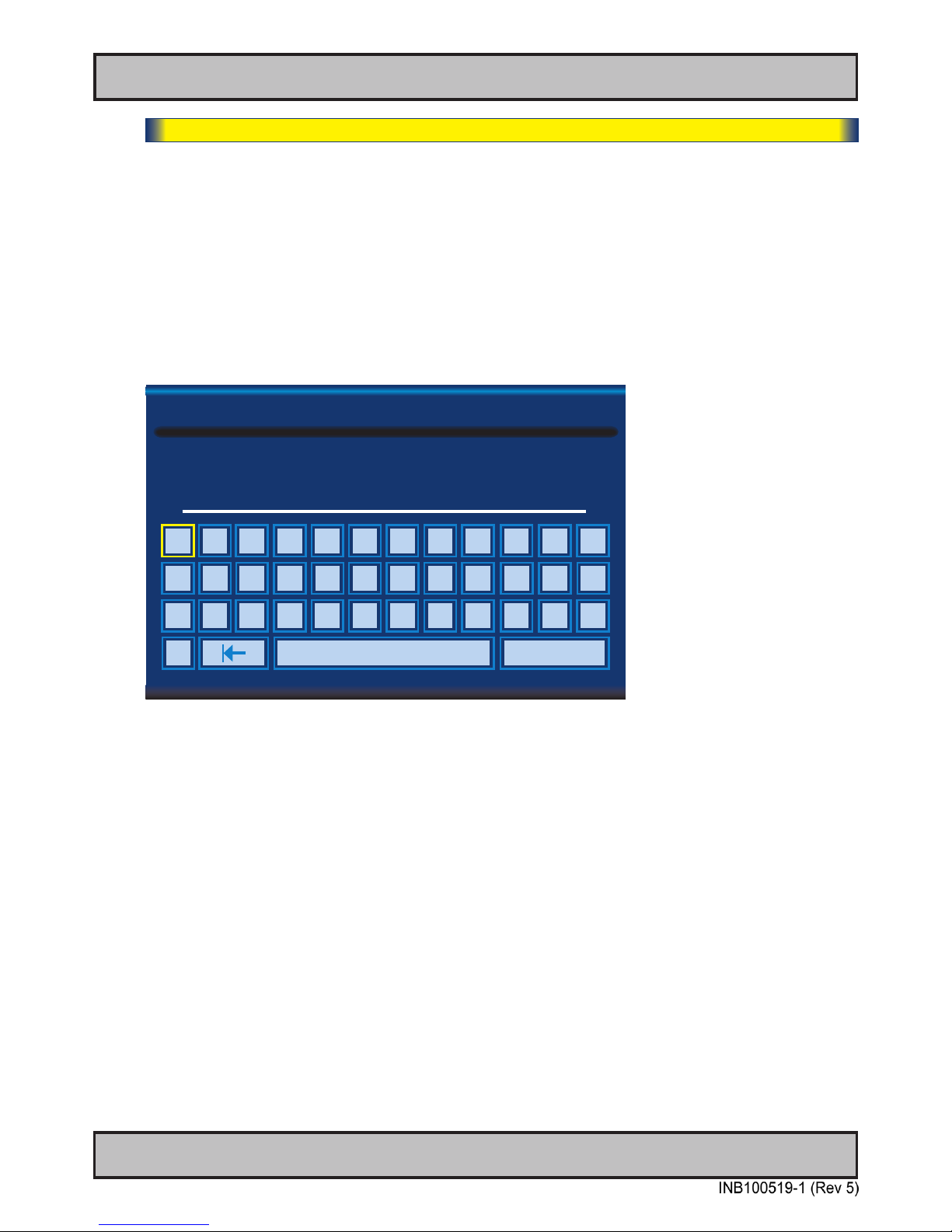
When activated, a requester on screen similar to a standard keyboard layout will appear.
Use the “(-) Brilliance (+)”, “(<) Navigation (>)” and “MENU” touch buttons to enter and edit the new
name. Below is an example for editing the “Source” input name. Only uppercased letters allowed.
The “|<” button will erase (backspace) the last character entered. Press “Enter” to save new name.
Yellow border around letter indicate selected character.
NAME:
Edit Source Label
NIGHT RA
A B C D E F G H I J K L
M
N O P Q R S T U V
W
X
Y Z 0 1 2 3 4 5 6 7 8 9
-
Space
Enter
Page 36
36
User Controls
IND100064-38
OSD Menu Functions
Image Settings
Lets you congure various visual preferences for any signal. The contents of these submenu are listed
below.
|---2---
Image Settings - Auto Position
Will automatically t the current displayed full screen signal and center it based on the active area of
the TFT display. This function rely on properties of the incoming signal.
● Note: This function will not try to scale or deform the image, so if the image looks stretched, please review the
Management Setting/Scaling function later in this manual to adjust it on pixel level. Available for RGB/VGA mode only.
|---2---
Image Settings - Auto Color Balance
Will automatically adjust the color balance of the current displayed full screen signal. This function
will analyse the incoming signal strength for RGB values and adjust it for “best eye visuality”. Colors
are automatically calculated based on a overall coloring model to attempt a more true, relevant and
correct look.
● Note: Available for RGB/VGA mode only.
|---2---
Image Settings - Brightness *Available in “Full Mode” only
Increase/decrease the black level saturation in real-time of the current displayed full screen signal.
Window overlays (PIP/PBP) and the OSD Menu overlay will be unaffected. A visual slider in the
OSD menu will show the current value. This value adjusts the TFT panel’s brightness by controlling
the voltage feed.
● Note: Value adjustable from 0 to 100. 50 is factory default.
|---2---
Image Settings - Contrast *Available in “Full Mode” only
Increase/decrease the contrast in real-time of the current displayed full screen signal. Window
overlays (PIP/PBP) and the OSD Menu overlay will be unaffected.
● Note: Value adjustable from 0 to 100. 50 is factory default.
|---2---
Image Settings - Saturation *Available in “Full Mode” only + Video Fullscreen
Increase/decrease the overall video color saturation/color amount of the current displayed full
screen image (no effect on DVI/VGA signals). Can be used if the incoming CVBS signal from older
equipment (due to bad cables) appear to have a lack of strong colors or just to generally make the
displayed image become more vivid. Note that this function can also make noisy color signals
appear crisper/clearer if adjusted to gray scales.
● Note: Value adjustable from 0 to 100. 50 is factory default.
Page 37
37
User Controls
IND100064-38
OSD Menu Functions
|---2---
Image Settings - Hue *Available in “Full Mode” only + Video Fullscreen
Allows to adjust/shift the main color properties of all Red, Green, Blue and Yellow (unique hues)
values. This can be useful for certain Composite Video sources (no effect on DVI/VGA signals)
whose output may have shifted or seems to be “out of phase”, where for instance blue seems more
dominant than green, red and yellow-ish colors. By using HUE one can shift the entire color range
of all components left or right in the spectrum.
● Note: Value adjustable from 0 to 100. 50 is factory default.
|---2---
Image Settings - Sharpness
Increase/decrease the overall image sharpness. This affects the active display area, and applies to
all signal inputs and window overlays (PIP/PBP). Use it to increase the visual quality of signals from
possible older equipment or improve electronically weak signals.
● Note: Value adjustable from 0 to 24. 12 is factory default. Available for RGB/VGA, CVBS modes only.
|---2---
Image Settings - Display
Allows to adjust DVI/VGA signals Horizontally (left/right) and Vertically (up/down) within the TFT
panel Active Area. If the incoming signal is “Analog VGA 1 (RGB/VGA)” only, Clock and Phase can
also be adjusted (if there seems to be a “waterfall / rolling bars” effect present in the active display
area).
● Note: This function can move information in the image outside the visible TFT Active Area, so use caution when
modifying this parameter. Try to determine the max end of borders (look at each corner) of the image before you
proceed using this function.
|--------3--------
Image Settings - Display - H Position
Settings as follows:
“H Position” = Move image within the TFT panel active area Horizontally (left/right),
values from 0 to 100.
● Note: Default value is centered inside the active TFT panel area.
|--------3--------
Image Settings - Display - V Position
Settings as follows:
“V.Position” = Move image within the TFT panel active area Vertically (up/down),
values from 0 to 100.
● Note: Default value is centered inside the active TFT panel area.
Page 38
38
User Controls
IND100064-38
OSD Menu Functions
|--------3--------
Image Settings - Display - Clock
Adjust the horizontal frequency (clock) of the analog signal to improve visibility of the entire
image. When it is adjusted, you will notice that the image will appear to be stretched and
might in some situations start to icker/scroll, at which point you must reverse the last
adjustment to stop it from ickering/scrolling anymore. This function can be used for older
signals that is not automatically detected by the internal display controller.
To adjust the Clock and Phase to a optimal setting it is recommended to display a image with
alternating white and black lines by stepped by 1 pixels either vertically or horizontally. It is
suggested to use a dedicated and external test pattern while adjusting.
● Note: Available for RGB/VGA mode only.
|--------3--------
Image Settings - Display - Phase
Fine tune the data sampling position of the signal (impacts on image quality). This function
will remove small transparent defects in typical characters where a portion seems to be more
faint then the nearby black pixels. The faint pixels are always visible as a line from top to
bottom (vertically). Note that this function is automatic and does not allow for manual values.
It is suggested to use a dedicated and external test pattern while adjusting.
● Note: Available for RGB/VGA mode only.
Page 39
39
User Controls
IND100064-38
OSD Menu Functions
|---2---
Image Settings - Video Setup *Available when Video Fullscreen only
Provides submenus where the following settings for Composite video signals are available:
|--------3--------
Image Settings - Video Setup - Main MADI mode
Motion Adaptive De-Interlacing. Motion adaptive de-interlacing is a pixel-based two-phase
process. Phase 1 involves the detection of motion and the generation of a motion value for
each pixel. These pixel motion values are used as a measure of the current “degree of
motion”. In Phase 2, the pixel motion values are used to select the appropriate de-interlacing
technique. As a result, areas of an image that are not moving will be fully static (flicker free)
and moving objects will have smooth edges.
Set to either “Normal”, “Adaptive” or “OFF”.
● Note: Default is OFF
|--------3--------
Image Settings - Video Setup - Noise Reduction
The media noise reduction block removes unwanted ringing and block noise from images
that have undergone MPEG or JPEG compression and decompression. The two types of
media noise that can be reduced are:
• Block Noise: MPEG encoders, in the presence of an almost flat area, can create a
squared structure due to the discrete 8x8 squares that are used in the MPEG
compression process. This creates a noticeable squared structure in the image.
The process smoothens these square boundaries so they are not visible. The
amount of smoothening is programmable between neighboring pixel values that will
be smoothened. The amount of smoothening starts to decrease linearly from the
maximum (defined by TO) to 0 (defined by 2 x TO) to avoid the hard switch effect of
the smoothening applied.
• Mosquito Noise: This process smoothenes checker box and discrete noise artifacts
referred to as Mosquito Noise around large edge transitions caused by MPEG
encoders.
This submenu will give you the following choices:
|-------------4-------------
Image Settings - Video Setup - Noise Reduction - Dynamic NR Mode
Dynamic NR (Noise Reduction) Mode can be set to either “High”, “Medium”, “Low”,
“Adaptive” or “OFF”. This is the “strength” of how much noise to detect and
automatically remove in order to enhance the overall image quality. The Block Noise
process will be used.
● Note: Default is OFF
Page 40
40
User Controls
IND100064-38
|-------------4-------------
Image Settings - Video Setup - Noise Reduction - MPEG NR Mode
MPEG NR (the generic coding of moving pictures and associated audio information)
can be set to either “ON” or “OFF”. This function will try to reduce noise as result from
compressed/formatted MPEG video streams. This noise is often seen as larger
blocks or containers of compressed pixels and is suitable to improve the visual
performance of video feeds capable of outputting direct MPEG streams. The Block
Noise process will be used.
● Note: Default is OFF
|-------------4-------------
Image Settings - Video Setup - Noise Reduction - Sharpness Noise Coring
Adjust the clarity after Noise Reduction was applied to the video signal. Can be set to
“High”, “Medium”, “Low”, “Adaptive” or “OFF”. The Mosquito Noise will be used.
● Note: Default is OFF
|--------3--------
Image Settings - Video Setup - Film Mode
This function will analyze the resolution and frames per second information in the video feed
and determine how to process/display each frame correctly (to avoid judder and staggering
playback), also referenced as “pull down method”. This option should be chosen to secure
that the video feed is at maximum quality and performance. 2:2 is suitable for PAL/SECAM
signals, while 2:3 is suitable for NTSC signals. 2:2-2:3 will try to conform to both standards
and may be suited in some cases for mixed incoming video feeds.
3:2 lm enables sequences of 24 Hz original lm content and convert this to an output of 48
Hz or 72 Hz vertical refresh rate. This feature reduces the noticeable uneven judder seen on
a 3:2 lm sequence that is converted to 60 Hz vertical refresh rate.
Set to either; “2:2”, “3:2”, “3:2-2:2” or “OFF”.
|--------3--------
Image Settings - Video Setup - DCDi
DCDI® BY Faroudja low-angle Diagonal interpolation. In addition to the advanced de interlacing capabilities mentioned in the previous sections, further image enhancement is
achieved by applying special processing to a moving lowangle diagonal pattern in a video
image. For motion video, the intra-field interpolation is done using the patented and highly
acclaimed DCDI® (Directional Correlational De-Interlacing) algorithm by Faroudja®.
Conventional Interpolation algorithms operate on the basis that the current pixel is related to
the pixels above and below it. This is untrue of diagonal edges. Whenever an edge is not
vertical, the way the current pixel depends on the angle of the edge is related to those
diagonally above and below it. Hence, conventional vertical Interpolation algorithms work
well on edges close to the horizontal and vertical directions. However, they will break down
completely as the angles of edges become more diagonal, causing jagged edge artifacts.
DCDi® by Faroudja computes and tracks the angles of edges and uses this information to
optimally fill in the missing pixels, removing jagged edge artifacts.
Set to either “ON” or “OFF”.
OSD Menu Functions
Page 41
41
User Controls
IND100064-38
Color Mode Settings
Lets you adjust the color temperature (Kelvin degrees) of the image. This applies to the Main Source signal.
Window overlays (PIP/PBP) and the OSD Menu overlay will be unaffected. Lower values make the image
appear warmer, while higher values will make it appear cooler. The contents of these submenus are listed
below.
Illustration (does not appear in menu): The Kelvin color temperature scale (approximate and symbolic):
1800K 4000K 5500K 8000K 12000K 16000K
|---2---
Color Mode Settings - Color Temperature
Set to either “9300K” (Cool, a blueish white), “8000K” (Neutral, a white close to natural light),
“6500K” (Warn, a reddish white) or “User”, (only available when Full Menu is active).
|--------3--------
Color Mode Settings - Color Temperature - User
Allows individual adjustment of Red, Green and Blue color gains. The selected setting will
be preserved for each signal input (DVI/RGB/CVBS...)
● Note: Value adjustable from 0 to 100. 50 is factory default.
|---2---
Color Mode Settings - Gamma *Available in “Full Mode” only + Video Fullscreen
This will activate the stored gamma curve color compensation as well as the LED indicators or
backlight brilliance used with ECDIS. Set to either “No Calibration”, “Calibration VGA” or “Calibration
DVI”, where these represents the two storage locations for compensation data. When either of them
are active, they will override the color temperature setting for the signal channel. Different signal
channels can be set to different settings that will be preserved.
This function is suitable for use with external equipment. Color temperature will be disabled.
● Note: Default is No Calibration with Gamma 2.2 and 140nits.
OSD Menu Functions
Page 42
42
User Controls
IND100064-38
Multi-PIP Settings
Lets you adjust how the Picture-in-Picture (PIP) or Picture-by-Picture (PBP) display mode is set up. The
default position of the rectangle is set to upper left corner of the Active Display area. Note that this requires
a valid incoming signal to be present in either the VGA or CVBS inputs. The contents of these submenus
are listed below.
|---2---
Multi-PIP Settings - PIP Mode
Settings as follows:
“PIP OFF” = Picture in Picture is inactive and the other PIP settings can not be
accessed.
“PIP Child” = The Secondary Source will be displayed in a small frame as an overlay
over the Main Source signal. When this function is activated a new menu
item will appear under “PIP Mode” called “PIP Display”.
“PIP Split” = The Main Source and Secondary signal sources are shown side-by-side
with the Main Source to the left and the Secondary Source to the right.
Note that only 50% of each source is actually visible on screen (split in two).
When this function is activated a new menu item will appear under “PIP
Mode” called “PIP Display”.
“PIP Wide” = The Main Source and Secondary signal sources are shown side-by-side in
widescreen mode with the Main Source to the left and the Secondary to the
right. When this function is activated a new menu item will appear under
“PIP Mode” called “PIP Display”.
● Note: Default is OFF
|---2---
Multi-PIP Settings - PIP Display *Available only when PIP Mode on
When PIP Child mode is active, the size and position of the rectangle displaying the Secondary
Source can be adjusted via the submenus below.
|--------3--------
Multi-PIP Settings - PIP Display -- PIP Child Size
Settings as follows:
“PIP Size” = Adjust the full size (H and V) for Secondary Source,
values from 0 to 7.
“PIP H-Size” = Adjust the Horizontal size for Secondary Source,
values from -10 to +10.
“PIP V-Size” = Adjust the Vertical size for Secondary Source,
values from -10 to +10.
● Note: Default value for all 3 functions is 0.
OSD Menu Functions
Page 43
43
User Controls
IND100064-38
|--------3--------
Multi-PIP Settings - PIP Position
When PIP Child mode is active, the size and position of the frame displaying the Secondary
Source can be adjusted by means of submenus for size and position respectively below.
Settings as follows:
“PIP H-Position” = Adjust the Horizontal (left/right) position for Secondary
Source, values from 0 to 100.
“PIP V-Position” = Adjust the Vertical (up/down) position for Secondary Source,
values from 0 to 100.
● Note: Default value for both functions is 0.
|---2---
Multi-PIP Settings - Swap Source
Swaps the Main and Secondary source signals (if present) including adjustments you may have
made, meaning that whatever is in Main Source will become the contents of the dened PIP
rectangle, and contents of the PIP rectangle to become full screen.
|---2---
Multi-PIP Settings - PIP Picture
When PIP mode is active, the picture appearance of the Secondary Source can be adjusted via the
following settings:
Settings as follows:
“Brightness” = Adjust the black level (brightness) of the Secondary Source, values from 0
to 100. Default is 50.
“Contrast” = Adjust the contrast of the Secondary Source, values from 0 to 100.
Default is 50.
“Saturation” = Adjust the overall color intensity of the Secondary Source, values from 0 to
100. Default is 50
“Hue” = Adjust the Hue color properties of the Secondary Source, values from 0 to
100. Default is 50.
“Sharpness” = Adjust the sharpness of the Secondary Source, values from 0 to 24.
Default is 12.
OSD Menu Functions
Page 44
44
User Controls
IND100064-38
OSD Settings
Allows you to customize the visual appearance of the On Screen Display (OSD) menu, such as; position,
transparency, time-out, assign hot keys, dene access modes and save, load and recall favourite settings
and more. The contents of these submenus are listed below.
|---2---
OSD Settings - OSD Position
Settings as follows:
“OSD H Position” = Place the OSD menu overlay Horizontally (left/right),
values from 0 to 100.
“OSD V Position” = Place the OSD menu overlay Vertically (up/down),
values from 0 to 100.
● Note: Default position of the OSD menu overlay is in the lower left corner of the of the Active Display area.
Default value for both functions is 100.
|---2---
OSD Settings - Language
Available OSD language to be used for all text and warnings that may appear.
Settings as follows:
“Norsk” = Display OSD in Norwegian.
“English” = Display OSD in English.
“Français” = Display OSD in French.
“Deutsch” = Display OSD in German.
“Italiano” = Display OSD in Italian.
“Español” = Display OSD in Spanish.
“日本語 “ = Display OSD in Japanese.
“簡體中文” = Display OSD in Simplied Chinese.
● Note: Current selected language is shown in green color. Default language is English.
|---2---
OSD Settings - Presets
Allow to work with Memory Presets (Recall/Save/Load) for OSD menu settings and overlays. The
contents of the submenu is listed below.
Settings as follows:
“Recall” = Reset back to factory defaults. Will override and restore all previous
modied settings.
OSD Menu Functions
Page 45
45
User Controls
IND100064-38
OSD Menu Functions
|--------3--------
OSD Settings - Presets - Save
Allows to save current state of all function and values to user dened presets. The
contents of the submenu is listed below.
Settings as follows:
“User 1” = Save all OSD settings to User 1 slot.
“User 2” = Save all OSD settings to User 2 slot.
“User 3” = Save all OSD settings to User 3 slot.
“User 4” = Save all OSD settings to User 4 slot.
“User 5” = Save all OSD settings to User 5 slot.
|--------3--------
OSD Settings - Presets - Load
Allows to save current state of all function and values to user dened presets. The
contents of the submenu is listed below.
Settings as follows:
“User 1” = Load all OSD settings from User 1 slot.
“User 2” = Load all OSD settings from User 2 slot.
“User 3” = Load all OSD settings from User 3 slot.
“User 4” = Load all OSD settings from User 4 slot.
“User 5” = Load all OSD settings from User 5 slot.
|---2---
OSD Settings - OSD Timer
Adjust the timeout in seconds that the OSD menu overlay is automatically exited and hidden from
view including locking mode (see OSD Lock Mode/Full Mode on next page). This timeout is counted
from last activity (navigation or adjusting parameters). The value is adjustable from 0 to 30 seconds.
● Note: Default timeout value is 10 seconds.
|---2---
OSD Settings - Transparent
Adjust the alpha blend also known as transparency of the OSD Menu overlay. It means that all
signal inputs and PIP/PBP images show through the OSD Menu. It is used when important
information on the display is necessary to be visible at all times.
● Note: Level adjustable from 0 to 7. 0 is factory default (no transparency/solid background color).
Page 46
46
User Controls
OSD Menu Functions
IND100064-38
|---2---
OSD Settings - OSD Mode
Conguring the OSD Mode to show as simplied/most common functions or advanced (full) setup.
Settings as follows:
“Simplied” = A few functions is not visible/available in this state. For most uses this
is the preferred setting and are safe for the display functionality and
continuous trusted operation on the unit.
“Full” = All functions and parameters is visible/available in this state. Some of the
settings adjusted could impact on display functionality and image quality.
Only experienced and qualied personnel should access and change
parameters when in this mode. Also, more technical details about signals,
frequency will be available. The layout of the OSD menu will also change
to a slightly bigger window with more menus and functions available.
● Note: Learn how to navigate and enter the correct code, by reading the “OSD Keycode / OSD Lock Mode”
introduction section earlier in this chapter.
● Note: When requesting a “Full” mode from a Simplified mode, the user are required to enter a key code.
This code is factory preset to “362”. You can enter the code by using navigation and “MENU” to confirm. After a
successful entering of the key code, the OSD menu will always be in this state during powered on. After a
power off and on to the unit, the OSD Mode will be reverted back to “Simplified” mode.
|---2---
OSD Settings - OSD Lock Mode
To prevent accidental or unwanted user intervention, you can set the behaviour of how the OSD
menu is accessible by the user including adjusting brightness via the “(-) Brilliance (+)” symbols.
Normally by factory default accessible by touching the “MENU” symbol on the front glass of the unit.
Settings as follows:
“Normal Mode” = Default accessible pop-up by touching the “MENU” symbol.
For Non-ECDIS Compliant usage.
“Password Protect” = Ask for key code rst (321) when the “MENU” symbol is touched on
the front glass and before the OSD menu will appear.
Required for ECDIS Compliance usage.
“Full Mode” = When activated: You will have to touch the “MENU” symbol for 5
seconds after which the key code requester will appear. Note that
only the “MENU” symbol will activate the password request, all other
touches on other symbols are ignored. After key code was entered
and accepted, the OSD menu will appear in which case you have
“x” seconds to use brilliance and power functions before all
functions are deactivated again and returns to “Full Mode”.
“x” value is dened as OSD Timeout value (see previous page).
● Note: Learn how to navigate and enter the correct code, by reading the “OSD Keycode / OSD Lock Mode”
introduction section earlier in this chapter.
Page 47
47
User Controls
OSD Menu Functions
IND100064-38
|---2---
OSD Settings - OSD Key Outdoor
To prevent accidental activation of Glass Display Control™ (GDC) touch functions, you can add an
extra layer of security on how “sensitve” the touch detection operates. This applies for “MENU”,
“(-) Brilliance (+)” and “Power Off” functions. The OSD Key Outdoor function is especially effective if
the unit is located in a outside environment where rain drops could potentionally trigger touch button
functions. Note that this setting does not apply for fullscreen sized touch screen glasses.
Settings as follows:
“Off” = All touch symbols operates normally.
“On” = Touch symbols responds when you press and hold it for 5 seconds.
|---2---
OSD Settings - Hot Key Assignment
Assign a commonly used OSD menu function to the available touch enabled Hot Keys which is
located on the front display glass. The following functions are available to assign and most of them
have a negative and positive counting logic. All of these functions are described before and after this
segment in the manual.
Settings as follows (for both “Key 1” and “Key 2”):
“Brightness” = Increase/Decrease Brightness of the TFT panel (not backlight).
“PIP Size” = Increase/Decrease the size of the Picture-In-Picture overlay.
“Main Source” = Flip up/down through the available signal sources (to full screen).
“Second Source” = Flip up/down through the available signal sources (to PIP/PBP).
“PIP Mode“ = Flip up/down through the PIP/PBP functions.
“Scaling” = Flip up/down through the scaling methods (Full, 1:1, Fill Aspect)
“Swap Source” = Swap the Main Source and Secondary Source appearance.
Both Hot Keys performs the same action.
“Test Pattern” = Display the internal test image overriding any signal inputs.
Both Hot Keys performs the same action.
“LED Drive” = Increase/Decrease the voltage level controlling LED Backlight which
affects the overall brightness strength (not via TFT panel itself).
“Language” = Flip up/down through available languages (real-time changes).
“No Function” = Nothing will be activated when user touches Hot Keys on front glass.
Both Hot Keys performs the same action.
● Note:Default Hot Keys are assigned to “No Function”. You can assign different functions to “Key 1“ and “Key 2”.
Page 48
48
User Controls
OSD Menu Functions
IND100064-38
Management Settings
Allows you to adjust overall settings for interaction/communication for the unit, such as scaling, zoom,
timing of signals, adjust voltages for LED (which illuminate the front glass symbols), sensitivity for the touch
control, VGA lter and Serial/Ethernet communication and more. The contents of these submenus are listed
below.
|---2---
Management Settings - Graphic Scaling *Available in “Full Mode” only
Allow to scale the currently displayed full screen signal in various ways. The contents of the
submenus is listed below.
|--------3--------
Management Settings - Graphic Scaling - Scaling
All scaling will performed from center of active display area and outwards in all directions.
Settings as follows:
“Fill Screen” = Zoom current full screen signal to ll the entire active display
area. Aspect ratio is ignored, which means that picture may
appear distorted or stretched.
“Fill to Aspect Ratio” = Zoom current full screen signal to ll the entire active display
area and preserve the aspect ratio. This means that you may
notice black bars without any image information either on
top/bottom or left/right of the centered image.
“1:1” = Zoom current full screen signal to ll the entire active display
area as 1:1 native pixel resolution. Example; if the incoming
signal is a 800x600, on a 1600x1200 unit, the incoming
signal will be shown 50% less in size and centered on
screen. Aspect ratio is kept unchanged.
|--------3--------
Management Settings - Scaling - Zoom
All zooming will performed from center of active display area and outwards in all directions.
Settings as follows:
“Zoom” = Zoom the current full screen signal horizontally and vertically
in equal steps. Values from 0 to 100.
● Note: Values under or over 50, may cause blurry and unfocused imagery, since it overrides the
external signal’s 1.1 pixel information and properties. Default value is 50.
Page 49
49
User Controls
OSD Menu Functions
IND100064-38
|--------3--------
Management Settings - Graphic Scaling - Horizont Stretch
All stretching will performed from center of active display area and outwards in one direction.
Settings as follows:
“Horizont Stretch” = Zoom/stretch current full screen signal in Horizontal
direction only (left and right). Values from 0 to 100.
● Note: Values under or over 50, may cause blurry and unfocused imagery, since it overrides the
external signal’s 1.1 pixel information and properties. Default value is 50.
|--------3--------
Management Settings - Graphic Scaling - Vertical Stretch
All stretch will performed from center of active display area and outwards in one direction.
Settings as follows:
“Vertical Stretch” = Zoom/stretch current full screen signal in Vertical direction
only (up and down). Values from 0 to 100.
● Note: Values under or over 50, may cause blurry and unfocused imagery, since it overrides the
external signal’s 1.1 pixel information and properties. Default value is 50.
|---2---
Management Settings - Auto Adjustment
Allow to let the video controller always perfom a Automatic Adjustment based on the detected
properties in the incoming signal or when incoming signal sources changes it’s properties real time.
It will scale and position incoming signal sources that has changed since the last detection was
executed successfully. Set to either “ON” or “OFF”.
● Note: This function is the same as the manual function found in “Image Settings - Auto Position” earlier described.
Default value is “OFF”.
Page 50
50
User Controls
OSD Menu Functions
IND100064-38
|---2---
Management Settings - Unknown Timing Search *Available in “Full Mode” only
Use this if you are unable to nd or detect the incoming full screen signal automatically (applies for
Analog VGA and CVBS video signals only. A PIP or PBP congured signal is not supported). It may
be a customized signal regarding resolution and refresh frequency. In these situations the custom
signal sources can be searched upon or entered manually within the OSD menu and even stored
conveniently. The contents of these submenus are listed below.
|--------3--------
Management Settings - Unknown Timing Search - Auto Mode
Try to determine the incoming signal by automatic detection routines which is based on a
known list of properties for resolutions and frequency combinations that fall out, but between
the most common industry standard set of resolutions/refresh frequencies.
Settings as follows:
“Display Size” = Force the Aspect Ratio to either to 4:3, 5:4, 1:1, 16:9 or
16:10
“Execute” = Choose to produce timing table, update the “Blind Mode
Data” and refresh the screen condition using the data of the
timing table. If this procedure seem to fail, use the “Blind
Mode” below to enter values manually.
|--------3--------
Management Settings - Unknown Timing Search - Blind Mode
If you know the advanced properties of the incoming signal or want to troubleshoot a
possible detected signal (that seem to have small deviations), you may try to adjust the
values below and see the result in real time. These settings should be performed by a skilled
technician or a individual that has the needed knowledge to do so. Internally these settings
below are saved into a data register called “Timing Table”.
Settings as follows:
“Hor. Resolution” = Set the Horizontal resolution of the timing table.
“Ver. Resolution” = Set the Vertical resolution of the timing table.
“Total Hor. Line” = Set the Total Horizontal Lines of the timing table.
“Hor. Blank Pixels” = Set the Horizontal Start of timing table,
(sync pulse + back porch).
“Ver. Blank Pixels” = Set the Vertical Start of timing table,
(sync pulse + back porch).
“Execute” = Choose to produce timing table and refresh the screen
condition using the data of the timing table.
● Note: You may experience fast, slow ickering or sliding lines during adjustments. This is normal, and
gives the indication that a different setting may have to be adjusted also, since all these functions are
connected to each other in order to create a stable signal that the video controller can display
correctly.
Page 51
51
User Controls
OSD Menu Functions
IND100064-38
|--------3--------
Management Settings - Unknown Timing Search - Save Timing
The current “Timing Table Data” that is currently visible in the “Blind Mode” or via the “Auto
Mode” functions may now be saved to a user dened slot. Available save slots from 1 to 8.
Saving “Time Table Data” may prove to be useful until the external equipment is either
replaced or changed. If so, you should use the “Clear Timing” function below to remove any
obsoleted “Timing Table Data” from time to time. Default save slot is 1.
|--------3--------
Management Settings - Unknown Timing Search - Clear Timing
Will allow to clear “Timing Table Data” currently saved / or not saved, based on the “Save
Timing” function above. You may clear save slots 1 to 8. Default chosen is 1.
|---2---
Management Settings - LED Drive
The touch enabled symbols available on the front glass of the unit is backlight illuminated by LED
technology. If you have the need to adjust the brightness strength of these LED (to conform with
Night Vision situations), you may do so by adjusting this value in real time.
Settings as follows:
“LED Drive” = Adjust values from 0 to 31.
● Note: Default is 31
|---2---
Management Settings - GDC Sensitivity *Available in “Full Mode” only
The touch enabled symbols known as GDC (Glass Display Control™) available on the front glass of
the unit can be adjusted in sensitivity. It basically means that a small value requires a larger area
to be covered longer over time, while a large value will require less smaller area to be covered in
less time. If you set the value too low or too high, you may feel a difference in either increased
responsiveness or the lack of such. By factory default, the most optimal value has been preset.
Settings as follows:
“GDC Sensitivity” = Adjust values from 0 to 100.
● Note: Default is model dependent and set by factory. Note that the difference between 0 and 100 is minimal,
as it is not suitable to go beyond a fair responsiveness that could cause accidental triggering of functions to
occur by nearby objects touching the glass (i.e. rain drops for instance, washing glass with cloth).
● Caution: If the sensitivity value was set very low, you may experience a increased occurence of non-
responsiveness which also affects accessing the correct menu function in order to re-adjust this value. It is
therefore suggested as a last resort solution to reset this value via SCOM (Serial/Ethernet Communication)
functionality instead by sending a “Reset Factory Default” (or “Load User Default”+Slot Number, if available
and previously stored by using “Save User Default”+Slot Number) commands if you are unable to navigate
the OSD menu.
Please review the appropriate Technical User Manual located here:
http://www.hatteland-display.com/pdink/inb100018-4.php
Page 52
52
User Controls
OSD Menu Functions
IND100064-38
|---2---
Management Settings - Filter *Available in “Full Mode” only
Filter (applies for VGA1 signal input only) is a Signal Noise Reduction technique to enhance
a possible weak or bad RGB/VGA signal. It will remove certain types of noise patterns typically
apparent in close proximity of other electronic equipment with less or lack of proper shielding to
prevent interference.
Settings as follows:
“Filter” = Set to either “ON” or “OFF”.
● Note: Default is “OFF”
|---2---
Management Settings - VGA Out *Available in “Full Mode” only
Set to either “Enable” or “Disable”. More information available later.
|---2---
Management Settings - VGA Sel *Available in “Full Mode” only
Set to either “Enable” or “Disable”. More information available later.
Page 53
53
User Controls
OSD Menu Functions
IND100064-38
|---2---
Management Settings - Communication *Available in “Full Mode” only
The unit allows for remote control (adjust brightness for example) and/or accessing internal
information about the unit such as typenumber, serial number and more. To setup this feature, you
rst need to congure the Serial or Ethernet protocol properly to match your external equipment
specications. The contents of the submenus is listed below.
Settings as follows:
“RS232” = Sets the internal communication to standard RS-232 protocol.
“2-wire RS-485” = Sets the internal communication to RS-485 protocol
(Half duplex).
“4-wire RS485/422” = Sets the internal communication to RS-485/422 protocol
(Full duplex).
“Address RS” = Set the global unique channel/port ID for the unit, 16 ID’s available.
“IP Address” = IP can be found Automatically or you can set the IP address
manually (xxx.xxx.xxx.xxx) for Ethernet protocol by choosing
“Fixed IP”.
“Download” = Allows Factory Firmware upgrade for the unit via RS-232 Serial
Communication.
● Note: Default mode is “RS232” protocol.
A more detailed description of the SCOM (Serial/Ethernet Communication) can be found here:
http://www.hatteland-display.com/pdink/inb100018-4.php
Review also the “Pinout Assignments” chapter in this manual for additional help during preperation
and/or installation of external equipment intended to communicate with.
Page 54
54
User Controls
OSD Menu Functions
IND100064-38
Service
Will show various technical and unit related information, such as; Firmware versions, Elapsed Time,
Internal Temperature, Fault Status and activation for the internal Test Pattern image useful for troubleshooting. Some of these functions are static information while others are accessible. Whenever you are in
contact with helpdesk or service personnel, they might require you to read back some of these values in
order to precisely pinpoint any problem/question you should have with the unit or its functionality.
Information blocks as follows:
“GEV Firmware Rev” = Displays the rmware version of the GEV videocontroller.
Example: “GEVHD-24 120120V2”
“CYP Firmware Rev” = Displays the rmware version of the touch enabled buttons.
Example: “120119R0V01”
“Ethernet Firmware Rev” = Displays the rmware version of the Ethernet controller.
Example: “E121003V1”
“Elapsed Time” = Shows the time elapsed in hours since rst-time power on.
Example: “180”
“Current Temperature” = Shows the internal temperature measured by onchip sensor.
Example: “+027.0 C”, in Celcius Degrees.
|---2---
Service - Fault Status
Will show detected Fault Staus by measuring various internal values for “DVI Chip”, “NVRAM”,
“DDC” and “TMP Sensor” during operation. Status is stated as either “OK” or “FAULT”. The contents
of this submenu is listed below.
Fault Status as follows:
“DVI Chip” = Status for on-board Digital Visual Interface graphics chip processor.
“NVRAM” = Status for Non-volatile random-access memory,
used to store parameters and settings.
“Ethernet” = Status for Ethernet/LAN communication chip controller.
“GDC” = Status for Glass Display Control™ (GDC) touch button controller.
“TMP Sensor” = Status for internal temperature measured by on-chip sensor.
Page 55
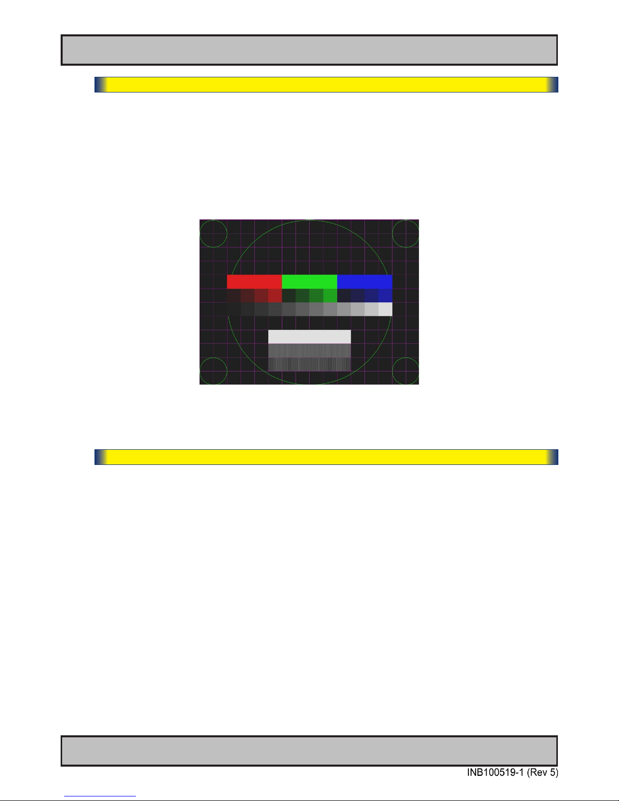
55
User Controls
OSD Menu Functions
IND100064-38
|---2---
Service - Test Pattern
Will show the internal test pattern with greyscales, colors and raster patterned boxes to check for
deviations in the TFT panel/display controller behaviour. It is independent of any current resolution
or specications found in the signal inputs. The test pattern is generated internally in the display
controller and is sent 1:1 directly to the TFT panel. It can be useful during trouble-shooting
situations to determine the source of a display or connectivity problem regarding external
equipment.
To active this function, touch the “MENU” button.
● Note: This function will not inform/report any deviations directly, you need to have the required technical
expertise to interpret the test pattern displayed.
|---2---
Service - Burn In
Sets the unit into “Burn In” mode and enables to write EDID data. More information to follow.
Page 56
56
This page left intentionally blank
Page 57
57
Specications
Page 58
58
IND100129-142
All specifications are subject to change without prior notice!
Specications - HD 12T21 MMD-xxx-Fxxx
SPECIFICATIONS
Note: All specifi cations are subject to change without prior notice!
Please visit www.hatteland-display.com for the latest electronic version.
• Native Resolution : 1024 x 768
• Pixel Pitch (RGB) : 0.24 (H) x 0.24 (V) mm
• Response Time Standard : 35ms (typical), black to white
• Response Time High Bright : 19ms (typical), black to white
• Contrast Ratio Standard : 700:1 (typical)
• Contrast Ratio High Bright : 600:1 (typical)
• Light Intensity Standard : 500 cd/m² (typical)
• Light Intensity High Bright : 1000 cd/m² (typical)
• Viewable Angle Standard : +/- 80 deg. (Up/Down/Left/Right) (typical)
• Viewable Angle High Bright : +/- 80 deg. (D/L/R), +/- 60 deg. (U) (typ)
• Active Display Area : 245.76 (H) x 184.32 (V) mm
• Max Colors : 16.7 million
• 314.00 (W) x 272.00 (H) x 64.50 (D) mm
• 12.36" (W) x 10.71" (H) x 2.54" (D)
• 4 x M6 VESA mounting 280x150mm, Max 12mm deep
• Weight: 3.8kg / 8.4lbs
• High Quality TFT with LED Backlight
• 12.1 inch viewable image size, Aspect Ratio 4:3
• TFT active-matrix liquid crystal panel
Power Supply options:
• 115&230VAC - 50/60Hz : HD 12T21 MMD-Cxx-Fxxx model
• 12-24 VDC (14VDC nominal) : HD 12T21 MMD-Fxx-Fxxx model
Power Consumption:
• Operating Standard : 21W (typ) - 60W (max)
• Operating High Bright : 29W (typ) - 60W (max)
A P P R O V A L S & C E R T I F I C A T E S
Physical Considerations:
TFT Technology:
TFT Characteristics:
Power Specifications:
This product have been tested / type approved by the following classification societies:
IEC 60945 4th (EN 60945:2002) IAC S E10 ClassNK - Nippon Kaiji Kyokai (Pending)
GL - Germanischer Lloyd DNV - Det Norske Veritas ABS - American Bureau of Shipping
CCS - China Classification Society (Pending) BV - Bureau Veritas LRS - Lloyd’s Register of Shipping (Pending)
Compass Safe Distance: HD 12T21 MMD-xxx-Fxxx Standard: 125cm Steering: 75cm
• Digital separate synchronization
• Composite synchronization
• Synchronization on green
• Auto detects VGA -> XGA, interlaced and non interlaced
• Video Signal : Analog RGB 0,7Vp-p
: Input Impedance 75 Ohm
Synchronization Range:
• Horizontal : 31.5 kHz to 91.1 kHz
• Vertical : 60 Hz* to 85 Hz
* Recommended for optimal picture quality
Resolutions:
• VGA : 640 x 480 (including 640 x 350)
• SVGA : 800 x 600 (including 720 x 400)
• XGA : 1024 x 768*
* Recommended for optimal picture quality
Video Signals:
• Interlaced HDTV, NTSC, PAL and SECAM video
• Composite video
Synchronization:
Supported Signals:
• DVI-D Signal IN : 2 x 24p DVI (female)
• RGB Signal IN : 2 x 15p HD D-SUB (female)
• Comp. Video IN : 3 x BNC connector (female)
• SCOM RS-422/485 : 1 x Phoenix Terminal Block 3.81, non-isolated+Buzzer
• RGB Signal OUT : 1 x 15p HD D-SUB (female) - Clone of RGB IN*
• If Touchscreen : 1 x USB TYPE A Connector (female)
• Ethernet : 1 x RJ45 Connector for Remote Control
• SCOM RS-232 : 1 x 9p D-SUB (female) non-isolated
• Potmeter : 1 x 9p D-SUB (male)
(Potentiometer IN, +5VDC OUT, BRT +/- IN)
• If AC Power IN : 1 x Std IEC Inlet
• If DC Power IN : 1 x 2p Phoenix MSTB 2,5/2-GF-5,08 THT
*Tested at recommended resolutions. The RGB output signal is at same resolution and
sync as the RGB input. The output is working even if the display unit is turned off, but
power cable/supply must be connected/provided.
Signal Terminals:
• Operating : Temperature -15 deg. C to +55 deg. C
- Humidity up to 95%
• Storage : Temperature -20 deg. C to +60 deg. C
- Humidity up to 95%
• IP Rating : Protection: IP66 front - IP22 rear (EN60529)
Safety Considerations:
Even although the test conditions for bridge units provide for a maximum
operating temperature of 55°C, continuous operation of all electronic
components should, if possible, take place at ambient temperatures of only
25°C. This is a necessary prerequisite for long life and low service costs.
Behind front bezel - Glass Display Control™ (GDC) IP66:
• Power On/Off, On Screen Display Menu, Brightness Control (-/+)
• Hotkeys (left/right), Mode/Status Indicator (Service)
• Buzzer (not visible), Light Sensor (not visible)
• Projected Capacitive Touch Screen (Multitouch, USB interface)
• Optical Bonding Technology
• Sunlight Readable / High Bright (includes Optical Bonding) model
• Single 12-24VDC Power Input
Environmental Considerations:
User Controls:
Factory Options:
For a full overview of typenumbers, please review the following link:
www.hatteland-display.com/pdflink/ind100780-3.php
• HD CMB SX1-A1 = 1 x Console Mount Kit
• HD 12BRD SX1-A1 = 1 x Mounting Bracket
• HD TMB SX1-A1 = 1 x Table Mount Bracket. EN60945 Tested*
Please see user manual/datasheet for more information
Available Accessories:
* Release date to be con rmed. Please contact us for more information.
Page 59
59
IND100129-143
All specifications are subject to change without prior notice!
Specications - HD 15T21 MMD-xxx-Fxxx
SPECIFICATIONS
Note: All specifi cations are subject to change without prior notice!
Please visit www.hatteland-display.com for the latest electronic version.
• Native Resolution : 1024 x 768
• Pixel Pitch (RGB) : 0.297 (H) x 0.297 (V) mm
• Response Time Standard : 8ms (typical), black to white
• Response Time High Bright : 19ms (typical), black to white
• Contrast Ratio Standard : 700:1 (typical)
• Contrast Ratio High Bright : 800:1 (typical)
• Light Intensity Standard : 400 cd/m² (typical)
• Light Intensity High Bright : 1000 cd/m² (typical)
• Viewable Angle Standard : +/- 80 deg. (Up/Down/Left/Right) (typical)
• Viewable Angle High Bright : +/- 80 deg. (D/L/R), +/- 60 deg. (U) (typ)
• Active Display Area : 304.1 (H) x 228.1 (V) mm
• Max Colors : 16.7 million
• 356.00 (W) x 307.00 (H) x 71.50 (D) mm
• 14.02" (W) x 12.09" (H) x 2.81" (D)
• 4 x M6 VESA mounting 280x150mm, Max 12mm deep
• Weight: 4.9kg / 10.8lbs
• High Quality TFT with LED Backlight
• 15.0 inch viewable image size, Aspect Ratio 4:3
• TFT active-matrix liquid crystal panel
Multi-power Supply:
• 115&230VAC - 50/60Hz + 24 VDC - HD 15T21 MMD-Mxx-Fxxx
Note: You may connect either AC power or DC power or both. In case both sources
are connected, power will be sourced from the AC input. If AC input is lost, there will
be a uninterrupted switch-over to DC input.
Power Consumption:
• Operating Standard : 22W (typ) - 60W (max)
• Operating High Bright : 34W (typ) - 60W (max)
A P P R O V A L S & C E R T I F I C A T E S
Physical Considerations:
TFT Technology:
TFT Characteristics:
Power Specifications:
This product have been tested / type approved by the following classification societies:
IEC 60945 4th (EN 60945:2002) I ACS E10 ClassNK - Nippon Kaiji Kyokai (Pending)
GL - Germanischer Lloyd DNV - Det Norske Veritas ABS - American Bureau of Shipping
CCS - China Classification Society (Pending) BV - Bureau Veritas LRS - Lloyd’s Register of Shipping (Pending)
Compass Safe Distance: HD 15T21 MMD-xxx-Fxxx Standard: 125cm Steering: 75cm
• Digital separate synchronization
• Composite synchronization
• Synchronization on green
• Auto detects VGA -> XGA, interlaced and non interlaced
• Video Signal : Analog RGB 0,7Vp-p
: Input Impedance 75 Ohm
Synchronization Range:
• Horizontal : 31.5 kHz to 91.1 kHz
• Vertical : 60 Hz* to 85 Hz
* Recommended for optimal picture quality
Resolutions:
• VGA : 640 x 480 (including 640 x 350)
• SVGA : 800 x 600 (including 720 x 400)
• XGA : 1024 x 768*
* Recommended for optimal picture quality
Video Signals:
• Interlaced HDTV, NTSC, PAL and SECAM video
• Composite video
Synchronization:
Supported Signals:
• DVI-D Signal IN : 2 x 24p DVI (female)
• RGB Signal IN : 2 x 15p HD D-SUB (female)
• Comp. Video IN : 3 x BNC connector (female)
• SCOM RS-422/485 : 1 x Phoenix Terminal Block 3.81, non-isolated+Buzzer
• RGB Signal OUT : 1 x 15p HD D-SUB (female) - Clone of RGB IN*
• If Touchscreen : 1 x USB TYPE A Connector (female)
• Ethernet : 1 x RJ45 Connector for Remote Control
• SCOM RS-232 : 1 x 9p D-SUB (female) non-isolated
• Potmeter : 1 x 9p D-SUB (male)
(Potentiometer IN, +5VDC OUT, BRT +/- IN)
• AC Power IN : 1 x Std IEC Inlet
• DC Power IN : 1 x 2p Phoenix MSTB 2,5/2-GF-5,08 THT
*Tested at recommended resolutions. The RGB output signal is at same resolution and
sync as the RGB input. The output is working even if the display unit is turned off, but
power cable/supply must be connected/provided.
Signal Terminals:
• Operating : Temperature -15 deg. C to +55 deg. C
- Humidity up to 95%
• Storage : Temperature -20 deg. C to +60 deg. C
- Humidity up to 95%
• IP Rating : Protection: IP66 front - IP22 rear (EN60529)
Safety Considerations:
Even although the test conditions for bridge units provide for a maximum
operating temperature of 55°C, continuous operation of all electronic
components should, if possible, take place at ambient temperatures of only
25°C. This is a necessary prerequisite for long life and low service costs.
Behind front bezel - Glass Display Control™ (GDC) IP66:
• Power On/Off, On Screen Display Menu, Brightness Control (-/+)
• Hotkeys (left/right), Mode Status Indicator (Service)
• Light Sensor (not visible), Buzzer (not visible)
• Projected Capacitive Touch Screen (Multitouch, USB interface)
• Optical Bonding Technology
• Sunlight Readable / High Bright (includes Optical Bonding) model
Environmental Considerations:
User Controls:
Factory Options:
For a full overview of typenumbers, please review the following link:
www.hatteland-display.com/pdflink/ind100780-3.php
• HD CMB SX1-A1 = 1 x Console Mount Kit
• HD 15BRD SX1-A1 = 1 x Mounting Bracket
• HD TMB SX1-A1 = 1 x Table Mount Bracket. EN60945 Tested*
Please see user manual/datasheet for more information
Available Accessories:
* Release date to be con rmed. Please contact us for more information.
Page 60
60
IND100129-144
All specifications are subject to change without prior notice!
Specications - HD 17T21 MMD-xxx-Fxxx
SPECIFICATIONS
Note: All specifi cations are subject to change without prior notice!
Please visit www.hatteland-display.com for the latest electronic version.
• 390.00 (W) x 351.00 (H) x 73.50 (D) mm
• 15.35" (W) x 13.82" (H) x 2.89" (D)
• 4 x M6 VESA mounting 280x150mm, Max 12mm deep
• Weight: 6.2kg / 13.6lbs
• High Quality TFT with LED Backlight
• 17.0 inch viewable image size, Aspect Ratio 5:4
• TFT active-matrix liquid crystal panel
• Native Resolution : 1280 x 1024
• Pixel Pitch (RGB) : 0.264 (H) x 0.264 (V) mm
• Response Time : 5ms (typical), “black” to “white”
• Contrast Ratio : 1000:1 (typical)
• Light Intensity Standard : 350 cd/m² (typical)
• Light Intensity High Bright : 1000 cd/m² (typical)
• Viewable Angle : +/- 80 deg. (typical) (Up/Down/Left/Right)
• Active Display Area : 337.92 (H) x 270.336 (V) mm
• Max Colors : 16.7 million
Multi-power Supply:
• 115&230VAC - 50/60Hz + 24 VDC - HD 17T21 MMD-Mxx-Fxxx
Note: You may connect either AC power or DC power or both. In case both sources
are connected, power will be sourced from the AC input. If AC input is lost, there will
be a uninterrupted switch-over to DC input.
Power Consumption:
• Operating Standard : 32W (typ) - 60W (max)
• Operating High Bright : TBD W (typ) - 60W (max)
A P P R O V A L S & C E R T I F I C A T E S
Physical Considerations:
TFT Technology:
TFT Characteristics:
Power Specifications:
This product have been tested / type approved by the following classification societies:
IEC 60945 4th (EN 60945:2002) I ACS E10 ClassNK - Nippon Kaiji Kyokai (Pending)
GL - Germanischer Lloyd DNV - Det Norske Veritas ABS - American Bureau of Shipping
CCS - China Classification Society (Pending) BV - Bureau Veritas LRS - Lloyd’s Register of Shipping (Pending)
Compass Safe Distance: HD 17T21 MMD-xxx-Fxxx Standard: 125cm Steering: 75cm
• Digital separate synchronization
• Composite synchronization
• Synchronization on green
• Auto detects VGA -> SXGA, interlaced and non interlaced
• Video Signal : Analog RGB 0,7Vp-p
: Input Impedance 75 Ohm
Synchronization Range:
• Horizontal : 31.5 kHz to 91.1 kHz
• Vertical : 60 Hz* to 85 Hz
* Recommended for optimal picture quality
Resolutions:
• VGA : 640 x 480 (including 640 x 350)
• SVGA : 800 x 600 (including 720 x 400)
• XGA : 1024 x 768
• SXGA : 1280 x 1024*
* Recommended for optimal picture quality
Video Signals:
• Interlaced HDTV, NTSC, PAL and SECAM video
• Composite video
Synchronization:
Supported Signals:
• DVI-D Signal IN : 2 x 24p DVI (female)
• RGB Signal IN : 2 x 15p HD D-SUB (female)
• Comp. Video IN : 3 x BNC Connector (female)
• SCOM RS-422/485 : 1 x Phoenix Terminal Block 3.81, non-isolated+Buzzer
• RGB Signal OUT : 1 x 15p HD D-SUB (female) - Clone of RGB IN*
• If Touchscreen : 1 x USB TYPE A Connector (female)
• Ethernet : 1 x RJ45 Connector for Remote Control
• SCOM RS-232 : 1 x 9p D-SUB (female) non-isolated
• Potmeter : 1 x 9p D-SUB (male)
(Potentiometer IN, +5VDC OUT, BRT +/- IN)
• AC Power IN : 1 x Std IEC Inlet
• DC Power IN : 1 x 2p Phoenix MSTB 2,5/2-GF-5,08 THT
*Tested at recommended resolutions. The RGB output signal is at same resolution and
sync as the RGB input. The output is working even if the display unit is turned off, but
power cable/supply must be connected/provided.
Signal Terminals:
• Operating : Temperature -15 deg. C to +55 deg. C
- Humidity up to 95%
• Storage : Temperature -20 deg. C to +60 deg. C
- Humidity up to 95%
• IP Rating : Protection: IP66 front - IP22 rear (EN60529)
Safety Considerations:
Even although the test conditions for bridge units provide for a maximum
operating temperature of 55°C, continuous operation of all electronic
components should, if possible, take place at ambient temperatures of only
25°C. This is a necessary prerequisite for long life and low service costs.
Behind front bezel - Glass Display Control™ (GDC) IP66:
• Power On/Off, On Screen Display Menu, Brightness Control (-/+)
• Hotkeys (left/right), Mode Status Indicators (ECDIS, Service)
• Buzzer (not visible), Light Sensor (not visible)
• Projected Capacitive Touch Screen (Multitouch, USB interface)
• Optical Bonding Technology
• Sunlight Readable / High Bright (includes Optical Bonding) model
• Color Calibrated models (ECDIS)
Environmental Considerations:
User Controls:
Factory Options:
For a full overview of typenumbers, please review the following link:
www.hatteland-display.com/pdflink/ind100780-3.php
• HD CMB SX1-A1 = 1 x Console Mount Kit
• HD 17BRD SX1-A1 = 1 x Mounting Bracket
• HD TMB SX1-B1 = 1 x Table Mount Bracket. EN60945 Tested*
Please see user manual/datasheet for more information
Available Accessories:
* Release date to be con rmed. Please contact us for more information.
Page 61
61
IND100129-145
All specifications are subject to change without prior notice!
Specications - HD 19T21 MMD-xxx-Fxxx
SPECIFICATIONS
Note: All specifi cations are subject to change without prior notice!
Please visit www.hatteland-display.com for the latest electronic version.
• 429.00 (W) x 382.00 (H) x 74.50 (D) mm
• 16.89" (W) x 15.04" (H) x 2.93" (D)
• 4 x M6 VESA mounting 280x150mm, Max 12mm deep
• Weight: 7.8kg / 17.2lbs
• High Quality TFT with LED Backlight
• 19.0 inch viewable image size, Aspect Ratio 5:4
• TFT active-matrix liquid crystal panel
• MVA (Multi-domain Vertical Alignment) LCD Technology
• Native Resolution : 1280 x 1024
• Pixel Pitch (RGB) : 0.294 (H) x 0.294 (V) mm
• Response Time : 20ms (typical), “black” to “white”
• Contrast Ratio : 1000:1 (typical)
• Light Intensity Standard : 300 cd/m² (typical)
• Light Intensity High Bright : 800 cd/m² (typical)
• Viewable Angle : +/- 89 deg. (typical) (Up/Down/Left/Right)
• Active Display Area : 376.32 (H) x 301.056 (V) mm
• Max Colors : 16.7 million
Multi-power Supply:
• 115&230VAC - 50/60Hz + 24 VDC - HD 19T21 MMD-Mxx-Fxxx
Note: You may connect either AC power or DC power or both. In case both sources
are connected, power will be sourced from the AC input. If AC input is lost, there will
be a uninterrupted switch-over to DC input.
Power Consumption:
• Operating Standard : 42W (typ) - 125W (max)
• Operating High Bright : 72W (typ) - 125W (max)
A P P R O V A L S & C E R T I F I C A T E S
Physical Considerations:
TFT Technology:
TFT Characteristics:
Power Specifications:
This product have been tested / type approved by the following classification societies:
IEC 60945 4th (EN 60945:2002) IAC S E10 ClassNK - Nippon Kaiji Kyokai (Pending)
GL - Germanischer Lloyd DNV - Det Norske Veritas ABS - American Bureau of Shipping
CCS - China Classification Society (Pending) BV - Bureau Veritas LRS - Lloyd’s Register of Shipping (Pending)
Compass Safe Distance: HD 19T21 MMD-xxx-Fxxx Standard: 125cm Steering: 75cm
• Digital separate synchronization
• Composite synchronization
• Synchronization on green
• Auto detects VGA -> SXGA, interlaced and non interlaced
• Video Signal : Analog RGB 0,7Vp-p
: Input Impedance 75 Ohm
Synchronization Range:
• Horizontal : 31.5 kHz to 91.1 kHz
• Vertical : 60 Hz* to 85 Hz
* Recommended for optimum picture quality
Resolutions:
• VGA : 640 x 480 (including 640 x 350)
• SVGA : 800 x 600 (including 720 x 400)
• XGA : 1024 x 768
• SXGA : 1280 x 1024*
* Recommended for optimum picture quality
Video Signals:
• Interlaced HDTV, NTSC, PAL and SECAM video
• Composite video
Synchronization:
Supported Signals:
• DVI-D Signal IN : 2 x 24p DVI (female)
• RGB Signal IN : 2 x 15p HD D-SUB (female)
• Comp. Video IN : 3 x BNC Connector (female)
• SCOM RS-422/485 : 1 x Phoenix Terminal Block 3.81, non-isolated+Buzzer
• RGB Signal OUT : 1 x 15p HD D-SUB (female) - Clone of RGB IN*
• If Touchscreen : 1 x USB TYPE A Connector. (female)
• Ethernet : 1 x RJ45 Connector for Remote Control
• SCOM RS-232 : 1 x 9p D-SUB (female) non-isolated
• Potmeter : 1 x 9p D-SUB (male)
(Potentiometer IN, +5VDC OUT, BRT +/- IN)
• AC Power IN : 1 x Std IEC Inlet
• DC Power IN : 1 x 2p Phoenix MSTB 2,5/2-GF-5,08 THT
*Tested at recommended resolutions. The RGB output signal is at same resolution and
sync as the RGB input. The output is working even if the display unit is turned off, but
power cable/supply must be connected/provided.
Signal Terminals:
• Operating : Temperature -15 deg. C to +55 deg. C
- Humidity up to 95%
• Storage : Temperature -20 deg. C to +60 deg. C
- Humidity up to 95%
• IP Rating : Protection: IP66 front - IP22 rear (EN60529)
Safety Considerations:
Even although the test conditions for bridge units provide for a maximum
operating temperature of 55°C, continuous operation of all electronic
components should, if possible, take place at ambient temperatures of only
25°C. This is a necessary prerequisite for long life and low service costs.
Behind front bezel - Glass Display Control™ (GDC) IP66:
• Power On/Off, On Screen Display Menu, Brightness Control (-/+)
• Hotkeys (left/right), Mode Status Indicators (ECDIS, Service)
• Buzzer (not visible), Light Sensor (not visible)
• Projected Capacitive Touch Screen (Multitouch, USB interface)
• Optical Bonding Technology
• Sunlight Readable / High Bright (includes Optical Bonding) model
• Color Calibrated models (ECDIS)
Environmental Considerations:
User Controls:
Factory Options:
For a full overview of typenumbers, please review the following link:
www.hatteland-display.com/pdflink/ind100780-3.php
• HD CMB SX1-A1 = 1 x Console Mount Kit
• HD TMB SX1-B1 = 1 x Table Mount Bracket. EN60945 Tested*
Please see user manual/datasheet for more information
Available Accessories:
* Release date to be con rmed. Please contact us for more information.
Page 62
62
IND100129-146
All specifications are subject to change without prior notice!
Specications - HD 24T21 MMD-xxx-Fxxx
SPECIFICATIONS
Note: All specifi cations are subject to change without prior notice!
Please visit www.hatteland-display.com for the latest electronic version.
• 593.00 (W) x 384.00 (H) x 70.00 (D) mm
• 23.35" (W) x 15.12" (H) x 2.76" (D)
• 4 x M6 VESA mounting 280x150mm, Max 12mm deep
• Weight: TBD kg
• High Quality TFT with LED Backlight
• 24.0 inch viewable image size, Widescreen, Aspect Ratio 16:9
• TFT active-matrix liquid crystal panel, RGB vertical stripe
• MVA (Multi-domain Vertical Alignment) LCD Technology
• Native Resolution : 1920 x 1080 (FHD)
• Pixel Pitch (RGB) : 0.276 (H) x 0.276 (V) mm
• Response Time : 25 ms (typical), “black” to “white”
• Contrast Ratio : 3000:1 (typical)
• Light Intensity Standard : 300 cd/m² (typical)
• Light Intensity High Bright : TBD
• Viewable Angle : +/- 89 deg. (typical) (Up/Down/Left/Right)
• Active Display Area : 531.36 (H) x 298.89 (V) mm
• Max Colors : 16.7 million
Multi-power Supply:
• 115&230VAC - 50/60Hz + 24 VDC - HD 24T21 MMD-Mxx-Fxxx
Note: You may connect either AC power or DC power or both. In case both sources
are connected, power will be sourced from the AC input. If AC input is lost, there will
be a uninterrupted switch-over to DC input.
Power Consumption:
• Operating Standard : 49W (typ) - 125W (max)
• Operating High Bright : TBD W (typ) - 125W (max)
A P P R O V A L S & C E R T I F I C A T E S
Physical Considerations:
TFT Technology:
TFT Characteristics:
Power Specifications:
This product have been tested / type approved by the following classification societies:
IEC 60945 4th (EN 60945:2002) IAC S E10 ClassNK - Nippon Kaiji Kyokai (Pending)
GL - Germanischer Lloyd DNV - Det Norske Veritas ABS - American Bureau of Shipping
CCS - China Classification Society (Pending) BV - Bureau Veritas LRS - Lloyd’s Register of Shipping (Pending)
Compass Safe Distance: HD 24T21 MMD-xxx-Fxxx Standard: 70cm Steering: 45cm
• Digital separate synchronization
• Composite synchronization
• Synchronization on green
• Auto detects VGA -> WUXGA, interlaced and non interlaced
• Video Signal : Analog RGB 0,7Vp-p
: Input Impedance 75 Ohm
Synchronization Range:
• Horizontal : 31.5 kHz to 91.1 kHz
• Vertical : 60 Hz* to 85 Hz
* Recommended for optimal picture quality
Resolutions:
• VGA : 640 x 480 (including 640 x 350)
• SVGA : 800 x 600 (including 720 x 400)
• XGA : 1024 x 768
• SXGA : 1280 x 1024
• UXGA : 1600 x 1200
• FHD : 1920 x 1080*
• WUXGA : 1920 x 1200
* Recommended for optimal picture quality
Video Signals:
• Interlaced HDTV, NTSC, PAL and SECAM video
• Composite video
Synchronization:
Supported Signals:
• DVI-D Signal IN : 2 x 24p DVI (female)
• RGB Signal IN : 2 x 15p HD D-SUB (female)
• Comp. Video IN : 3 x BNC Connector (female)
• SCOM RS-422/485 : 1 x Phoenix Terminal Block 3.81, non-isolated+Buzzer
• RGB Signal OUT : 1 x 15p HD D-SUB (female) - Clone of RGB IN*
• If Touchscreen : 1 x USB TYPE A Connector (female)
• Ethernet : 1 x RJ45 Connector for Remote Control
• SCOM RS-232 : 1 x 9p D-SUB (female) non-isolated
• Potmeter : 1 x 9p D-SUB (male)
(Potentiometer IN, +5VDC OUT, BRT +/- IN)
• AC Power IN : 1 x Std IEC Inlet
• DC Power IN : 1 x 2p Phoenix MSTB 2,5/2-GF-5,08 THT
*Tested at recommended resolutions. The RGB output signal is at same resolution and
sync as the RGB input. The output is working even if the display unit is turned off, but
power cable/supply must be connected/provided.
Signal Terminals:
• Operating : Temperature -15 deg. C to +55 deg. C
- Humidity up to 95%
• Storage : Temperature -20 deg. C to +60 deg. C
- Humidity up to 95%
• IP Rating : Protection: IP66 front – IP22 rear (EN60529)
Safety Considerations:
Even although the test conditions for bridge units provide for a maximum
operating temperature of 55°C, continuous operation of all electronic
components should, if possible, take place at ambient temperatures of only
25°C. This is a necessary prerequisite for long life and low service costs.
Behind front bezel - Glass Display Control™ (GDC) IP66:
• Power On/Off, On Screen Display Menu, Brightness Control (-/+)
• Hotkeys (left/right), Mode Status Indicators (ECDIS, Service)
• Buzzer (not visible), Light Sensor (not visible)
• Projected Capacitive Touch Screen (Multitouch, USB interface)
• Optical Bonding Technology
• Sunlight Readable / High Bright (includes Optical Bonding) model*
• Color Calibrated models (ECDIS)
Environmental Considerations:
User Controls:
Factory Options:
For a full overview of typenumbers, please review the following link:
www.hatteland-display.com/pdflink/ind100780-3.php
• HD CMB SX1-B1 = 1 x Console Mount Kit
• HD TMB SX1-C1 = 1 x Table Mount Bracket. EN60945 Tested
Please see user manual/datasheet for more information
Available Accessories:
* Release date to be con rmed. Please contact us for more information.
Page 63
63
IND100129-154
All specifications are subject to change without prior notice!
Specications - HD 26T21 MMD-xxx-Fxxx
SPECIFICATIONS
Note: All specifi cations are subject to change without prior notice!
Please visit www.hatteland-display.com for the latest electronic version.
• 621.00 (W) x 435.00 (H) x 98.20 (D) mm
• 24.45" (W) x 17.13" (H) x 3.86" (D)
• 4 x M6 VESA mounting 280x150mm, Max 12mm deep
• Weight: 14.8kg / 32.6lbs
• High Quality TFT with CCFL Backlight
• 25.54 inch viewable image size, Widescreen, Aspect Ratio 16:10
• S-MVA, Active Matrix, Thin Film Transistor (TFT)
• RGB Vertical Stripe
• Native Resolution : 1920 x 1200
• Pixel Pitch (RGB) : 0.2865 (H) x 0.2865 (V) mm
• Response Time : 8 ms (typical), "gray" to "gray"
• Contrast Ratio : 1500:1 (typical)
• Light Intensity Standard : 350 cd/m
2
(typical)
• Light Intensity High Bright : TBD
• Viewable Angle : +/- 88 deg. (typical) (Up/Down/Left/Right)
• Active Display Area : 550.08 (H) x 343.8 (V) mm
• Max Colors : 16.7 million
Multi-power Supply:
• 115&230VAC - 50/60Hz + 24 VDC - HD 26T21 MMD-Mxx-Fxxx
Note: You may connect either AC power or DC power or both. In case both sources
are connected, power will be sourced from the AC input. If AC input is lost, there will
be a uninterrupted switch-over to DC input.
Power Consumption:
• Operating AC/DC: 107W (typ) - 125W (max)
A P P R O V A L S & C E R T I F I C A T E S
Physical Considerations:
TFT Technology:
TFT Characteristics:
Power Specifications:
This product have been tested / type approved by the following classification societies: (*=pending)
IEC 60945 4th (EN 60945:2002) IAC S E10 ClassNK - Nippon Kaiji Kyokai* GL - Germanischer Lloyd
DNV - Det Norske Veritas ABS - American Bureau of Shipping CCS - China Classification Society* BV - Bureau Veritas
LRS - Lloyd’s Register of Shipping*
• Digital separate synchronization
• Composite synchronization
• Synchronization on green
• Auto detects VGA -> WUXGA, interlaced and non interlaced
• Video Signal : Analog RGB 0,7Vp-p
: Input Impedance 75 Ohm
Synchronization Range:
• Horizontal : 31.5 kHz to 91.1 kHz
• Vertical : 60 Hz* to 85 Hz
* Recommended for optimal picture quality
Resolutions:
• VGA : 640 x 480 (including 640 x 350)
• SVGA : 800 x 600 (including 720 x 400)
• XGA : 1024 x 768
• SXGA : 1280 x 1024
• UXGA : 1600 x 1200
• FHD : 1920 x 1080
• WUXGA : 1920 x 1200*
* Recommended for optimal picture quality
Video Signals:
• Interlaced HDTV, NTSC, PAL and SECAM video
• Composite video
Synchronization:
Supported Signals:
• DVI-D Signal IN : 2 x 24p DVI (female)
• RGB Signal IN : 2 x 15p HD D-SUB (female)
• Comp. Video IN : 3 x BNC Connector (female)
• SCOM RS-422/485 : 1 x Phoenix Terminal Block 3.81, non-isolated+Buzzer
• RGB Signal OUT : 1 x 15p HD D-SUB (female) - Clone of RGB IN*
• If Touchscreen : 1 x USB TYPE A Connector (female)
• Ethernet : 1 x RJ45 Connector for Remote Control
• SCOM RS-232 : 1 x 9p D-SUB (female) non-isolated
• Potmeter : 1 x 9p D-SUB (male)
(Potentiometer IN, +5VDC OUT, BRT +/- IN)
• AC Power IN : 1 x Std IEC Inlet
• DC Power IN : 1 x 2p Phoenix MSTB 2,5/2-GF-5,08 THT
*Tested at recommended resolutions. The RGB output signal is at same resolution and
sync as the RGB input. The output is working even if the display unit is turned off, but
power cable/supply must be connected/provided.
Signal Terminals:
• Operating : Temperature -15 deg. C to +55 deg. C
- Humidity up to 95%
• Storage : Temperature -20 deg. C to +60 deg. C
- Humidity up to 95%
• IP Rating : Protection: IP66 front – IP22 rear (EN60529)
• Compass Safe Dist. : HD26T21MMD-xxx-Fxxx - Std: 130cm Steering: 70cm
Safety Considerations:
Even although the test conditions for bridge units provide for a maximum
operating temperature of 55°C, continuous operation of all electronic
components should, if possible, take place at ambient temperatures of only
25°C. This is a necessary prerequisite for long life and low service costs.
Behind front bezel - Glass Display Control™ (GDC) IP66:
• Power On/Off, On Screen Display Menu, Brightness Control (-/+)
• Hotkeys (left/right), Mode Status Indicators (ECDIS, Service)
• Buzzer (not visible), Light Sensor (not visible)
• Capacitive Touch Screen (USB interface)*
• Optical Bonding Technology
• Sunlight Readable / High Bright (includes Optical Bonding) model*
• Color Calibrated models (ECDIS)
• Single AC Power 115&230VAC - 50/60Hz Input
Environmental Considerations:
User Controls:
Factory Options:
For a full overview of typenumbers, please review the following link:
www.hatteland-display.com/pdflink/ind100780-3.php
• HD CMB SX1-C1 = 1 x Console Mount Kit
• HD TMB SX1-C1 = 1 x Table Mount Bracket. EN60945 Tested
Please see user manual/datasheet for more information
Available Accessories:
* Release date to be con rmed. Please contact us for more information.
Page 64
64
This page left intentionally blank
Page 65
65
Technical Drawings
Page 66
66
IND100132-218
Technical Drawings - HD 12T21 MMD-xxx-Fxxx
This document is the property of Hatteland Display AS. This document and any authorized reproduction thereof, must not be used in any way against the interest of Hatteland Display AS.
Any authorized reproduction, in whole or in part, must include this legend. Hatteland Display Proprietary information. Not to be distributed to any third party without written permission.
Dimensions might be shown with or without decimals and indicated as mm [inches]. Tolerance on drawings is +/- 1mm. For accurate measurements, check relevant DWG file.
TBD, DRAWINGS PENDING
Page 67
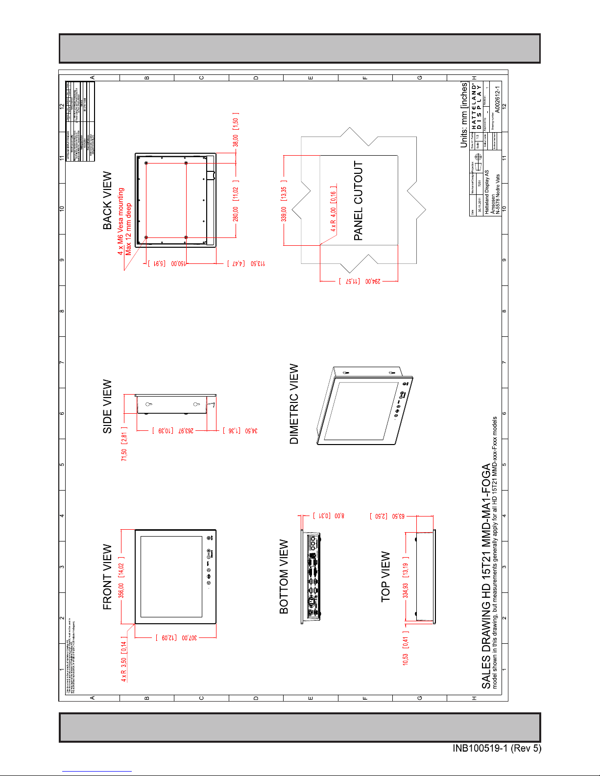
67
IND100132-219
Technical Drawings - HD 15T21 MMD-xxx-Fxxx
This document is the property of Hatteland Display AS. This document and any authorized reproduction thereof, must not be used in any way against the interest of Hatteland Display AS.
Any authorized reproduction, in whole or in part, must include this legend. Hatteland Display Proprietary information. Not to be distributed to any third party without written permission.
Dimensions might be shown with or without decimals and indicated as mm [inches]. Tolerance on drawings is +/- 1mm. For accurate measurements, check relevant DWG file.
Page 68
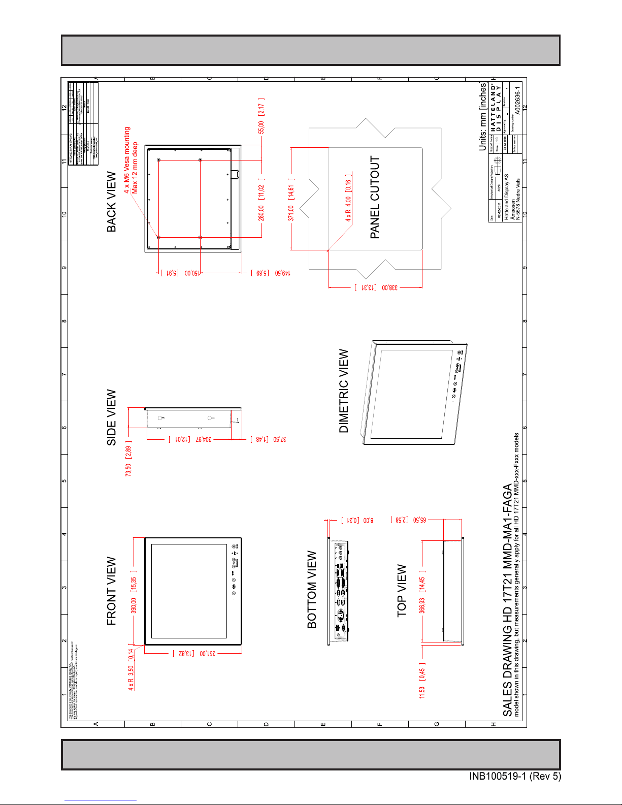
68
IND100132-220
Technical Drawings - HD 17T21 MMD-xxx-Fxxx
This document is the property of Hatteland Display AS. This document and any authorized reproduction thereof, must not be used in any way against the interest of Hatteland Display AS.
Any authorized reproduction, in whole or in part, must include this legend. Hatteland Display Proprietary information. Not to be distributed to any third party without written permission.
Dimensions might be shown with or without decimals and indicated as mm [inches]. Tolerance on drawings is +/- 1mm. For accurate measurements, check relevant DWG file.
Page 69
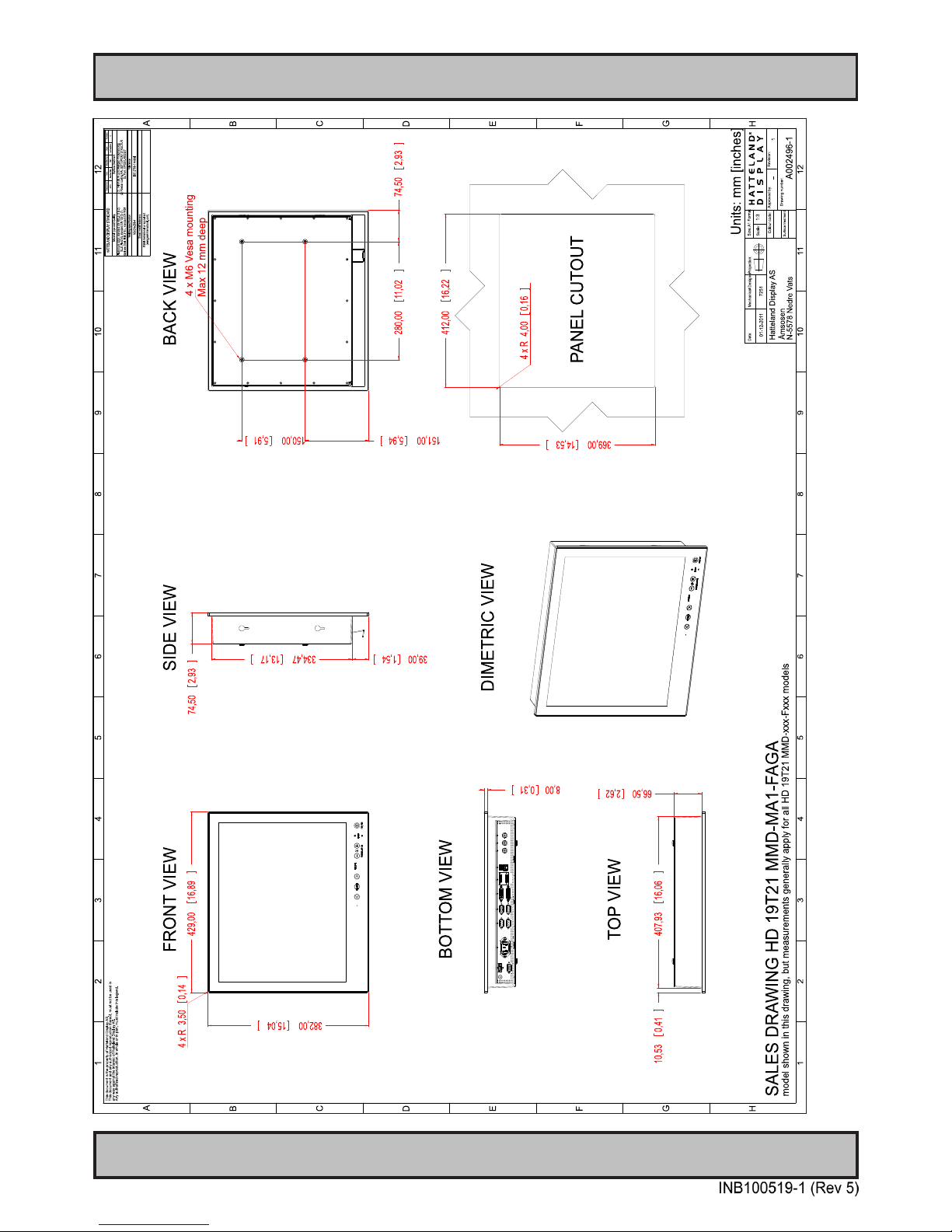
69
IND100132-221
Technical Drawings - HD 19T21 MMD-xxx-Fxxx
This document is the property of Hatteland Display AS. This document and any authorized reproduction thereof, must not be used in any way against the interest of Hatteland Display AS.
Any authorized reproduction, in whole or in part, must include this legend. Hatteland Display Proprietary information. Not to be distributed to any third party without written permission.
Dimensions might be shown with or without decimals and indicated as mm [inches]. Tolerance on drawings is +/- 1mm. For accurate measurements, check relevant DWG file.
Page 70
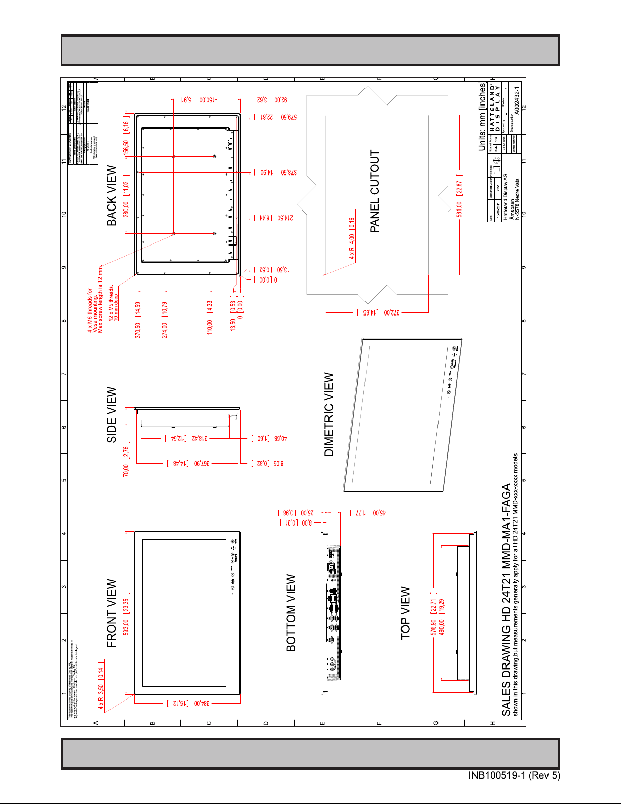
70
IND100132-222
Technical Drawings - HD 24T21 MMD-xxx-Fxxx
This document is the property of Hatteland Display AS. This document and any authorized reproduction thereof, must not be used in any way against the interest of Hatteland Display AS.
Any authorized reproduction, in whole or in part, must include this legend. Hatteland Display Proprietary information. Not to be distributed to any third party without written permission.
Dimensions might be shown with or without decimals and indicated as mm [inches]. Tolerance on drawings is +/- 1mm. For accurate measurements, check relevant DWG file.
Page 71
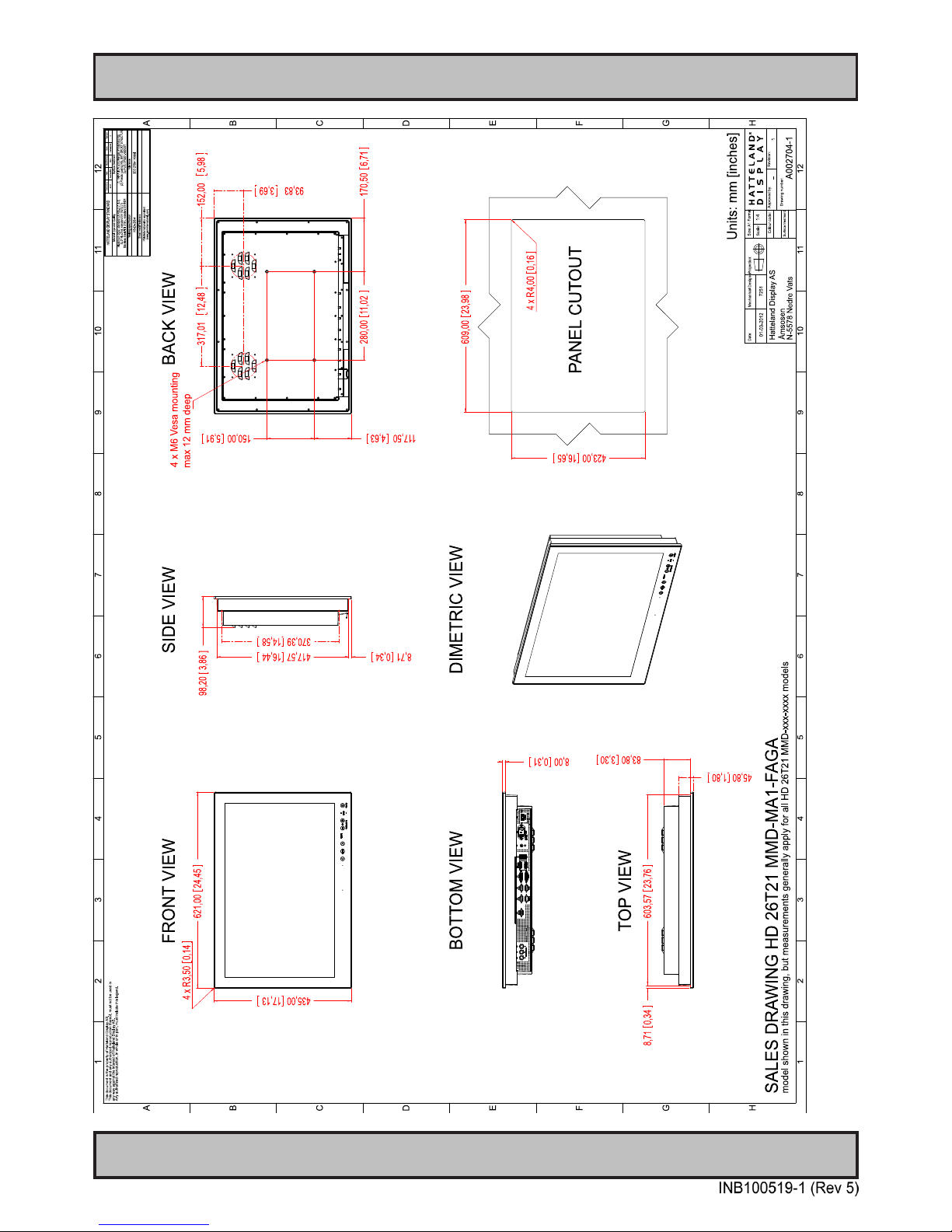
71
IND100132-236
Technical Drawings - HD 26T21 MMD-xxx-Fxxx
This document is the property of Hatteland Display AS. This document and any authorized reproduction thereof, must not be used in any way against the interest of Hatteland Display AS.
Any authorized reproduction, in whole or in part, must include this legend. Hatteland Display Proprietary information. Not to be distributed to any third party without written permission.
Dimensions might be shown with or without decimals and indicated as mm [inches]. Tolerance on drawings is +/- 1mm. For accurate measurements, check relevant DWG file.
Page 72
72
This page left intentionally blank
Page 73
73
Technical Drawings - Accessories
Page 74
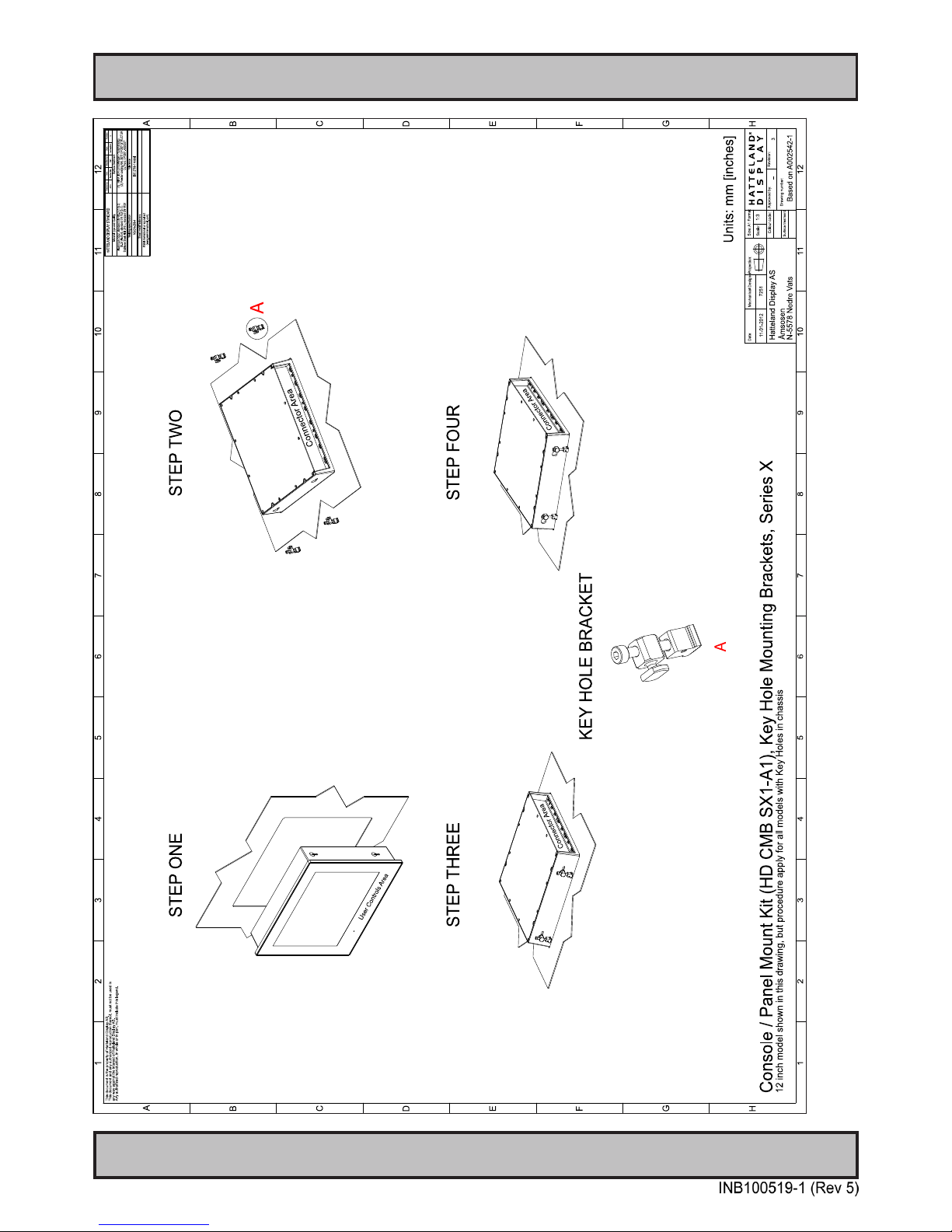
74
IND100132-229
This document is the property of Hatteland Display AS. This document and any authorized reproduction thereof, must not be used in any way against the interest of Hatteland Display AS.
Any authorized reproduction, in whole or in part, must include this legend. Hatteland Display Proprietary information. Not to be distributed to any third party without written permission.
Dimensions might be shown with or without decimals and indicated as mm [inches]. Tolerance on drawings is +/- 1mm. For accurate measurements, check relevant DWG file.
Technical Drawings - HD CMB SX1-A1
Console Mount Kit 12”,15”,17”,19”
Page 75
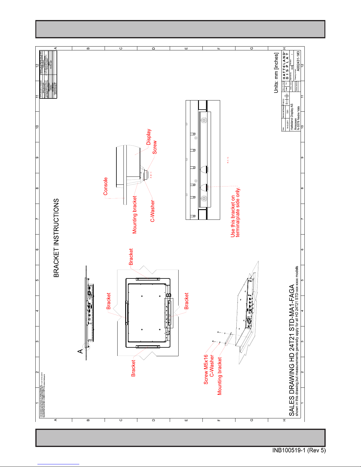
75
IND100132-240
This document is the property of Hatteland Display AS. This document and any authorized reproduction thereof, must not be used in any way against the interest of Hatteland Display AS.
Any authorized reproduction, in whole or in part, must include this legend. Hatteland Display Proprietary information. Not to be distributed to any third party without written permission.
Dimensions might be shown with or without decimals and indicated as mm [inches]. Tolerance on drawings is +/- 1mm. For accurate measurements, check relevant DWG file.
Technical Drawings - HD CMB SX1-B1
Console Mount Kit 24”
Page 76
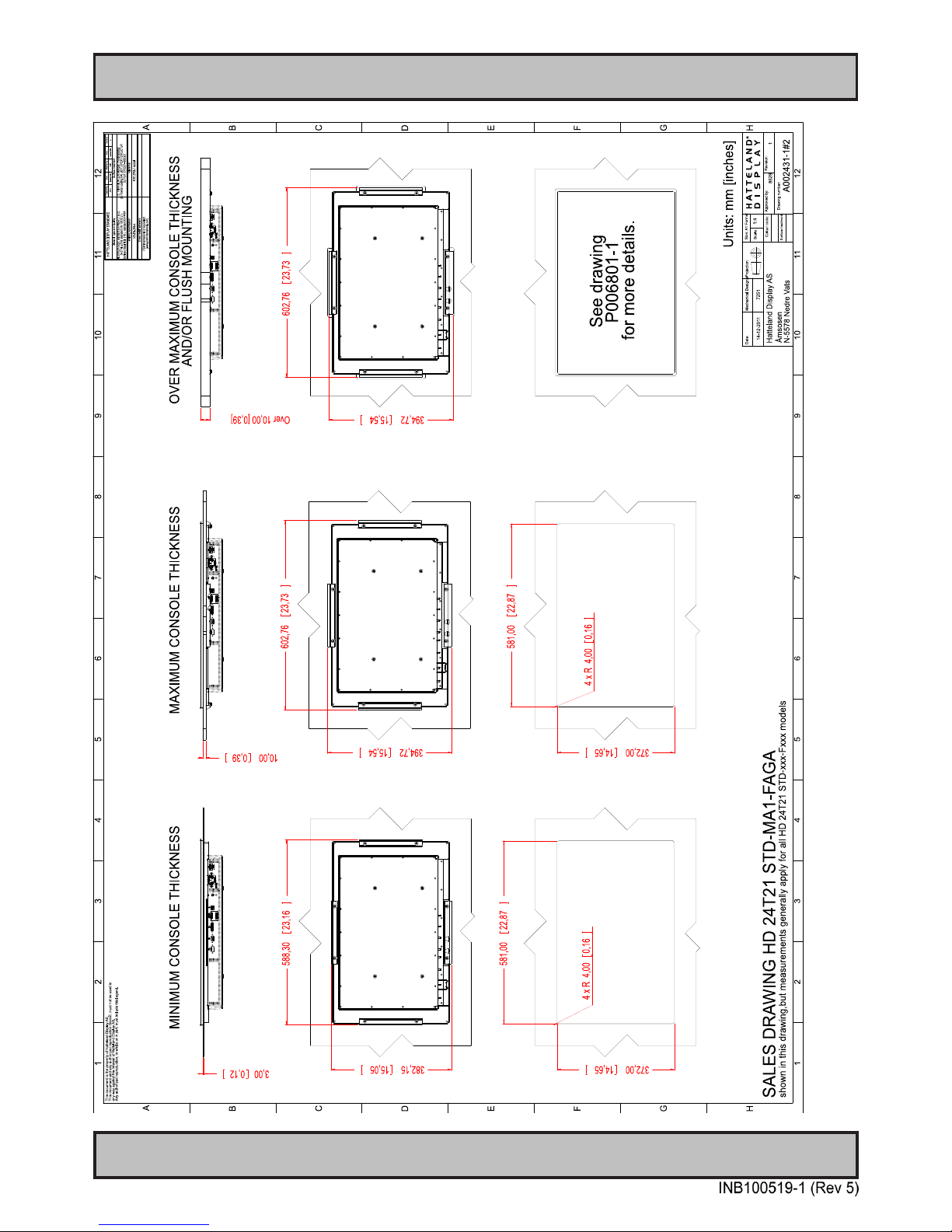
Technical Drawings - HD CMB SX1-B1
76
IND100132-240
This document is the property of Hatteland Display AS. This document and any authorized reproduction thereof, must not be used in any way against the interest of Hatteland Display AS.
Any authorized reproduction, in whole or in part, must include this legend. Hatteland Display Proprietary information. Not to be distributed to any third party without written permission.
Dimensions might be shown with or without decimals and indicated as mm [inches]. Tolerance on drawings is +/- 1mm. For accurate measurements, check relevant DWG file.
Console Mounting 24”
Page 77
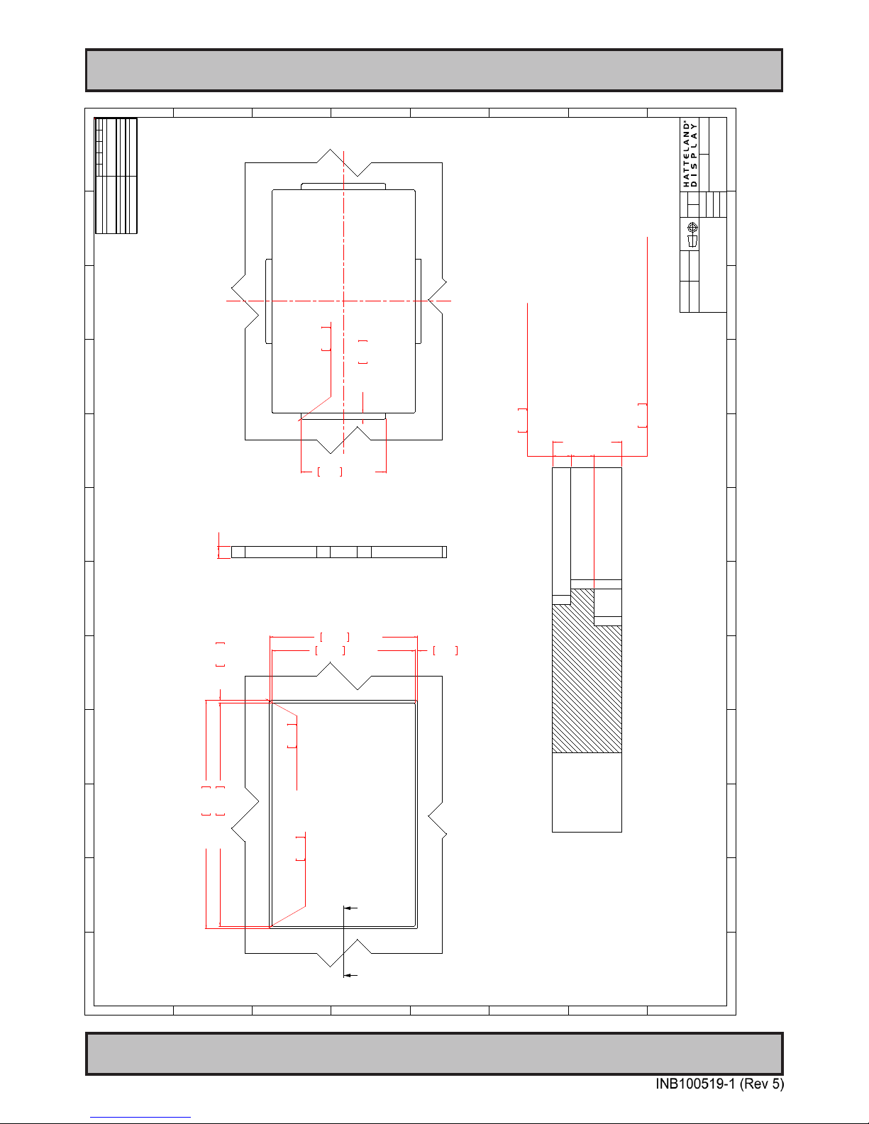
Technical Drawings - HD CMB SX1-B1
77
IND100132-240
This document is the property of Hatteland Display AS. This document and any authorized reproduction thereof, must not be used in any way against the interest of Hatteland Display AS.
Any authorized reproduction, in whole or in part, must include this legend. Hatteland Display Proprietary information. Not to be distributed to any third party without written permission.
Dimensions might be shown with or without decimals and indicated as mm [inches]. Tolerance on drawings is +/- 1mm. For accurate measurements, check relevant DWG file.
Flush Mounting 24”
FRONT VIEW SIDE VIEW BACK VIEW
PANEL CUTOUT FOR HD 24T21 XXX-XXX-XXXX, FLUSH MOUNTING.
Units: mm [inches]
H
12
G
F
E
3
4
56
D
C
B
A
123
4
56
78
78
G
F
E
9 10
D
C
B
1 1 1 2
A
9 10 11 12
H
07-11-2011
7251
Hatteland Display AS
Åmsosen
N-5578 Nedre Vats
P006801-1
Date:
Mechanical Designer
Projection:
This document is the property of Hatteland Display AS.
This document and any authorized reproduction thereof, must not be used in
any way against the interest of Hatteland Display AS.
Any authorized reproduction, in whole or in part, must include this legend.
--
1
Revision:
Approved by:
Drawing number:
HATTELAND DISPLAY STANDARD
Material type and Quality: Surface treatment:
Sheet metal fasteners:
Welding specification Tolerance:
Aluminium 5052; standard EN 485-2 (1 & 2)
St-37 Alu/Zink; standard EN 10215 (1)
Stainless Steel AISI 316 L; standard EN 4404
(1) TRIKATION (Zinc/Mangan Phosphatizing)
(2) Powder coating RAL 9011 EPOXY STRUCTUR
Du Pont: EP0301-4950327
PSM International or equivalent
(www.psminternational.com)
NS-EN-288-4
ISO 2768-1 middel
Created by:
4701
Date:
23-09-2004
Modified by:
7251
Date:
14-03-2008
Revision
2
Size: A1 Format
1:3
Colour code:
Scale:
Surface treatment:
581,00 22,87
372,00
14,65
594,00
23,39
385,00 15,16
4 x R
4,00
0,16
4 x R
4,00
0,16
6,50 0,26
6,50 0,26
AA
Console thickness.
16,00 0,63
220,00 8,66
4 x R
4,00
0,16
C
L
C
L
8,00 Sunken face for Display.0,31
10,00 Max thickness for mounting the bracket.0,39
Console thickness.
A-A (2 : 1)
Page 78

78
INB100519-1 (Rev 5)
This page left intentionally blank
Page 79
79
Appendixes
Page 80
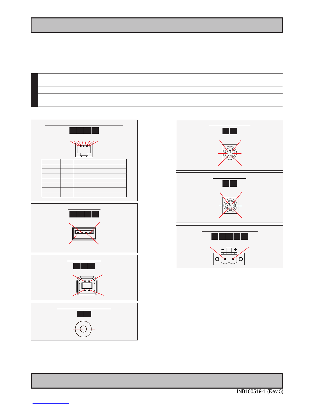
80
IND100241-13
Appendix
Pinout Assignments
2 pin DC Power Input, Phoenix
1 2 3 A B
Pin 2: Negative - Pin 1: Positive +
ID’s (1,2,3,A,B) denotes where connector is (by factory default) or may be available (through factory customization).
Note that some combinations may not be possible due to space restrictions. List also valid for customized models.
All pin out assignments are seen from users Point of View (POV) while looking straight at the connector.
Some connectors are not available on certain units due to product range specications. Please review the dedicated
datasheet or technical drawings for your actual unit to identify and determine the presence of desired connector.
1 Available for MMD (Maritime Multi Displays) units.
2 Available for STD (Industrial Standard Displays) units.
3 Available for MMC (Maritime Multi Computers / Panel Computers) units.
A For 8/13 inch sizes only
B For 12/15/17/19/24/26 inch sizes only
1 pin RCA/BNC COMP. VIDEO
1 B
Ground Shield
Pin 1: Video Signal
5 pin PS/2 KEYBOARD
3 B
Pin 1: Keyboard Data
Pin 3: Ground
Pin 5: Keyboard Clock
Pin 2: Not Connected
Pin 4: Vcc +5V
Pin 6: Not Connected
5 pin PS/2 MOUSE
3 B
Pin 1: Mouse Data
Pin 3: Ground
Pin 5: Mouse Clock
Pin 2: Not Connected
Pin 4: Vcc +5V
Pin 6: Not Connected
4 pin USB TYPE B
2 A B
Pin 2: Negative Data
Pin 3: Positive Data
Pin 4: Ground
Pin 1: VCC +5V
4 pin USB TYPE A
1 3 A B
Pin 2: Negative Data
Pin 1: VCC +5V
Pin 3: Positive Data
Pin 4: Ground
8 pin RJ45 10/100/1000mbps LAN/Ethernet
1 3 A B
1 2 3 4 5 6 7 8
PIN 01 D0P+ Differential Pair 0 (Positive)
PIN 02 D0N- Differential Pair 0 (Negative)
PIN 03 D1P+ Differential Pair 1 (Positive)
PIN 04 D2P+ Differential Pair 2 (Positive)
PIN 05 D2N- Differential Pair 2 (Negative)
PIN 06 D1N- Differential Pair 1 (Negative)
PIN 07 D3P+ Differential Pair 3 (Positive)
PIN 08 D3N- Differential Pair 3 (Negative)
Page 81
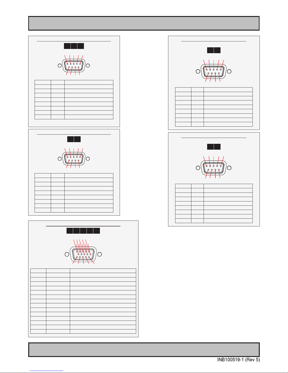
Pinout Assignments
81
IND100241-13
Appendix
15 pin DSUB High Density Analog RGB/VGA
1 2 3 A B
5 4 3 2 1
15 14 13 12 11
10 9 8 7 6
PIN 01 RED Red, analog
PIN 02 GREEN Green, analog
PIN 03 BLUE Blue, analog
PIN 04 ID2/RES Reserved for monitor ID bit 2 (grounded)
PIN 05 GND Digital ground
PIN 06 RED_RTN Analog ground red
PIN 07 GREEN_RTN Analog ground green
PIN 08 BLUE_RTN Analog ground blue
PIN 09 KEY/PWR +5V power supply for DDC (optional)
PIN 10 GND Digital ground
PIN 11 ID0/RES Reserved for monitor ID bit 0 (grounded)
PIN 12 ID1/SDA DDC serial data
PIN 13 HSYNC. Horizontal sync or composite sync, input
PIN 14 VSYNC. Vertical sync, input
PIN 15 ID3/SCL DDC serial clock
9 pin DSUB Serial COM RS-232 non-isolated
1 2 B
5 4 3 2 1
9 8 7 6
PIN 01 BUZ+ Buzzer Control Positive*
PIN 02 TxD Transmit Data
PIN 03 RxD Receive Data
PIN 04 DTR Data Terminal Ready
PIN 05 GND Ground
PIN 06 DSR Data Set Ready
PIN 07 RTS Request To Send
PIN 08 CTS Clear To Send
PIN 09 BUZ- Buzzer Control Negative*
*Wake On Ring is not enabled
9 pin DSUB Serial COM RS-485/RS-422
Full Duplex Mode
3 B
5 4 3 2 1
9 8 7 6
PIN 01 TxD- Transmit Data Negative
PIN 02 TxD+ Transmit Data Positive
PIN 03 RxD+ Receive Data Positive
PIN 04 RxD- Receive Data Negative
PIN 05 GND Signal Ground
PIN 06 N/C No internal connection
PIN 07 N/C No internal connection
PIN 08 N/C No internal connection
PIN 09 N/C No internal connection
9 pin DSUB Serial COM RS-485/RS-422
Half Duplex Mode
3 B
5 4 3 2 1
9 8 7 6
PIN 01 Res. Reserved, do not connect
PIN 02 Res. Reserved, do not connect
PIN 03 Data+ Data Positive
PIN 04 Data- Data Negative
PIN 05 GND Signal Ground
PIN 06 N/C No internal connection
PIN 07 N/C No internal connection
PIN 08 N/C No internal connection
PIN 09 N/C No internal connection
9 pin DSUB Serial COM RS-232 non-isolated
3 B
5 4 3 2 1
9 8 7 6
PIN 01 DCD Data Carrier Detect
PIN 02 RxD Receive Data
PIN 03 TxD Transmit Data
PIN 04 DTR Data Terminal Ready
PIN 05 GND Signal Ground
PIN 06 DSR Data Set Ready
PIN 07 RTS Request To Send
PIN 08 CTS Clear To Send
PIN 09 RI Ring Indicator
Page 82
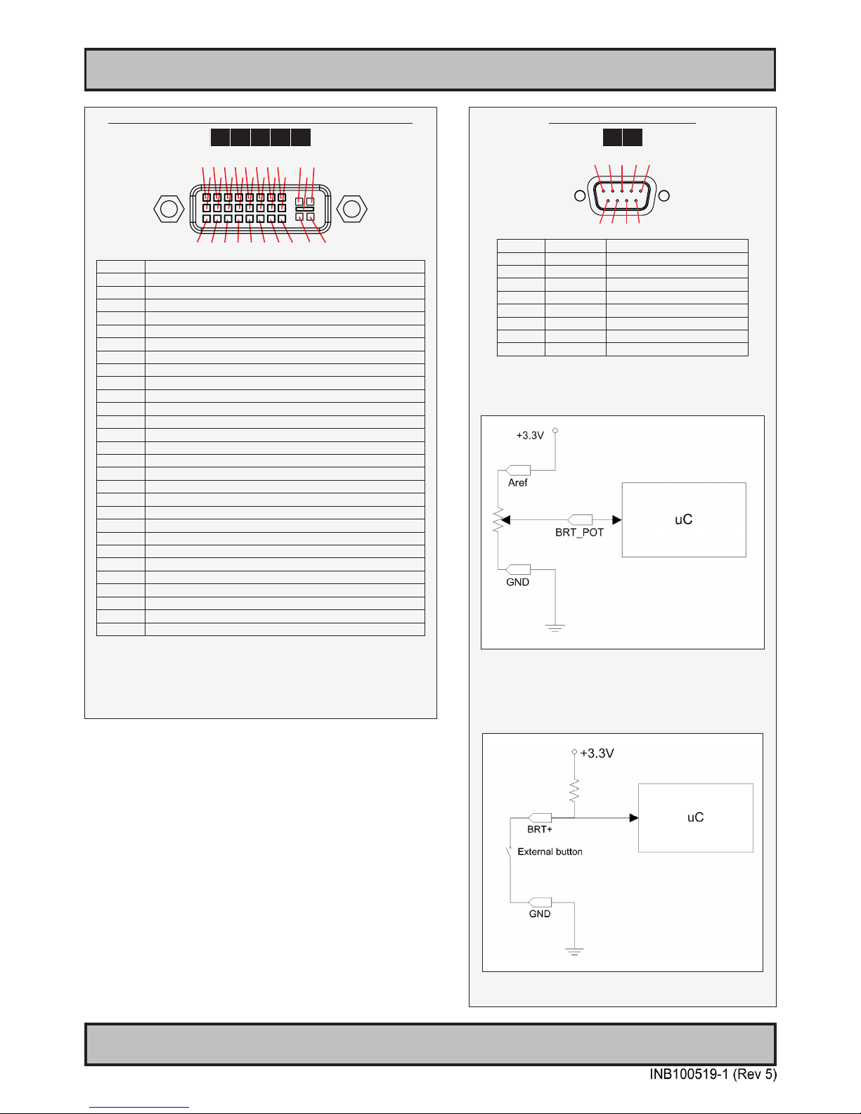
Pinout Assignments
82
IND100241-13
Appendix
18/24/24+5 pin DVI-D, DVI-I, Single Link, Dual Link Combined
1 2 3 A B
1 2 3 4 5 6 7 8 C1 C2
9 10 11 12 13 14 15 16 C5
17 18 19 20 21 22 23 24 C3 C4
PIN 01 T.M.D.S. Data2 - (Digital - RED link 1)
PIN 02 T.M.D.S. Data2 + (Digital + RED link 1)
PIN 03 T.M.D.S. Data2/4 Shield
PIN 04 T.M.D.S. Data4 - (Digital - GREEN link 2)
PIN 05 T.M.D.S. Data4 + (Digital + GREEN link 2)
PIN 06 DDC Clock
PIN 07 DDC Data
PIN 08 Analog Vertical Sync (DVI-I only)
PIN 09 T.M.D.S. Data1 - (Digital - GREEN link 1)
PIN 10 T.M.D.S. Data1 + (Digital + GREEN link 1)
PIN 11 T.M.D.S. Data1/3 Shield
PIN 12 T.M.D.S. Data3 - (Digital - BLUE link 2)
PIN 13 T.M.D.S. Data3 + (Digital + BLUE link 2)
PIN 14 +5V Power (for standby mode)
PIN 15 Ground (for +5V and analog sync)
PIN 16 Hot Plug Detect
PIN 17 T.M.D.S. Data0 - (Digital - BLUE link 1) and digital sync.
PIN 18 T.M.D.S. Data0 + (Digital + BLUE link 1) and digital sync.
PIN 19 T.M.D.S. Data0/5 Shield
PIN 20 T.M.D.S. Data5 - (Digital - RED link 2)
PIN 21 T.M.D.S. Data5 + (Digital - RED link 2)
PIN 22 T.M.D.S. Clock Shield
PIN 23 T.M.D.S. Clock + (Digital clock + (Links 1 and 2)
PIN 24 T.M.D.S. Clock - (Digital clock - (Links 1 and 2)
PIN C1 Analog RED
PIN C2 Analog GREEN
PIN C3 Analog BLUE
PIN C4 Analog Horizontal Sync.
PIN C5 Analog Ground (return for RGB signals)
DDC = Display Data Channel.
.M.D.S = Transition Minimized Differential Signal
PIN C1,C2,C3,C4 = Only present on DVI-I connectors.
NOTE: Connector shows a DUAL LINK design, but some units may not support it.
Only units with 1920x1200 or more in resolution require / support DUAL LINK.
9 pin DSUB Potmeter Control
1 B
5 4 3 2 1
9 8 7 6
PIN 01 +5V +5V out
PIN 02 Res. Reserved, do not connect
PIN 03 Res. Reserved, do not connect
PIN 04 Aref For potensiometer
PIN 05 +12V +12V out
PIN 06 BRT_POT Potmeter in
PIN 07 BRT – Button in
PIN 08 BRT+ Button in
PIN 09 GND Ground
Potentiometer shall be 10kΩ and
connected like this illustration below:
The BRT+ and BRT- can be used for controlling the
brilliance by using external buttons. Example for
the BRT+ input below:
Page 83
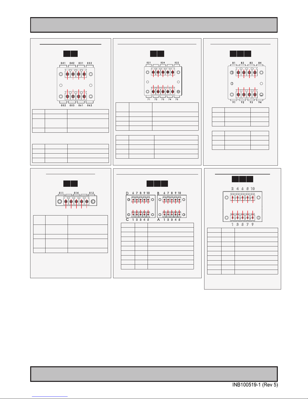
Pinout Assignments
83
IND100241-13
Appendix
5 pin Digital Output Module
“Safety Signal Relay”
3 A
X1
DIG
OUT
1 2 3 4 5
PIN 1 X1 - Out: 11
COM (Common
Center Terminal)
PIN 2 X1 - N/C
Not Connected
Not in use
PIN 3 X1 - Out: 14 NO (Normally Open)
PIN 4 X1 - N/C
Not Connected
Not in use
PIN 5 X1 - Out: 12 NC (Normally Closed)
8 pin CAN I/O Module, 2 channels
“HT 00254 OPT-A1”
3 A B
X8
CAN1
X9
CAN2
1 2 3 4
1 2 3 4
Pin 1 X8 - Can1: 81 In Low
Pin 2 X8 - Can1: 82 Out Low
Pin 3 X8 - Can1: 83 In High
Pin 4 X8 - Can1: 84 Out High
Pin 1 X9 - Can2: 91 In Low
Pin 2 X9 - Can2: 92 Out Low
Pin 3 X9 - Can2: 93 In High
Pin 4 X9 - Can2: 94 Out High
8 pin Digital Output / Input Module
“Solid State Relay”
3 A
X1
DIG
OUT
X1
DIG
IN
1 2 3 4
1 2 3 4
Pin 1 X1 - Out: 41 Out +
Pin 2 X1 - Out: 42 Out -
Pin 3 X1 - Out: 31
COM (Common Center
Terminal) *
Pin 4 X1 - Out: 32 NC (Normally Closed)*
* IEC 60950 Compliant, 48VDC
Pin 1 X1 - In: 52 +24VDC
Pin 2 X1 - In: 53 GND (Ground)
Pin 3 X1 - In: 61 +24VDC
Pin 4 X1 - In: 62 +Input
10 pin Digital Output / Input & Serial Module
“Mechanical Relay & COM (isolated RS-422/485)”
3 A
X1
DIG
OUT
X7
SER
I/O
1 2 3 4 5
1 2 3 4 5
PIN 1 X1 - Out: 21
COM (Common Center
Terminal)
PIN 2 X1 - N/C Not Connected / Not used
PIN 3 X1 - Out: 24 NO (Normally Open)
PIN 4 X1 - N/C Not Connected / Not used
PIN 5 X1 - Out: 22 NC (Normally Closed)
PIN 1 X7 - In: 71 Rx+ (Receive Data +)
PIN 2 X7 - In: 72 Rx- (Receive Data -)
PIN 3 X7 - Out: 73 Tx+ (Transmit Data +)
PIN 4 X7 - Out: 74 Tx- (Transmit Data -)
PIN 5 X7 - GND: 75 SGnd (Signal Ground)
10 pin RS-422 / RS-485 NMEA Module, 2 ports
“PCA100293-1”
3 A B
6 7 8 9 10
1 2 3 4 5
6 7 8 9 10
1 2 3 4 5
PIN 1 TxD- Transmit Data Negative
PIN 2 TxD+ Transmit Data Positive
PIN 3 GND Isolated Ground
PIN 4 RxD- Receive Data Negative
PIN 5 RxD+ Receive Data Positive
PIN 6 TxD- Transmit Data Negative
PIN 7 TxD+ Transmit Data Positive
PIN 8 GND Isolated Ground
PIN 9 RxD- Receive Data Negative
PIN 10 RxD+ Receive Data Positive
10 pin RS-422 / RS-485 Module
1 2 B
2 4 6 8 10
1 3 5 7 9
PIN 1* RxD+ Receive Data Positive
PIN 2 GND Ground
PIN 3* RxD- Receive Data Negative
PIN 4 +5V +5V Out
PIN 5* TxD+ Transmit Data Positive
PIN 6 BUZ- Buzzer Control Negative
PIN 7* TxD- Transmit Data Negative
PIN 8 BUZ+ Buzzer Control Positive
PIN 9 GNDR Ground 100Ω
PIN 10 GND Ground
*Pin 1,3,5,7 = RS-485 Full Duplex (4-wire)
*Pin 5,7 = RS-485 Half Duplex (2-wire)
Page 84
84
IND100077-8
Appendix
Basic Trouble-shooting
GENERAL ISSUES FOR TFT PANEL BASED PRODUCTS
Note: Applies for a range of various products. This is only meant as a general guide.
NO PICTURE / LED BEHAVIOUR:
If there is no light at all in the LED at the FRONT, check power cables. If the LED in front is green then check if the
brightness is set/adjusted to max brightness. Lack of image is most likely to be caused by incorrect connection, lack of
power or wrong BIOS settings.
SCROLLING / UNSTABLE IMAGE:
Signal cable may not be completely connected to computer or TFT display. Check the pin assignments and signal
timings of the display and your video card with respect to recommended timing and pin assignments. Make sure that
the video card is compatible and that it is properly seated / installed on the computer.
DISPLAY AREA IS NOT CENTERED / SIZED CORRECTLY
Make sure that a supported video mode has been selected on the display, or on the video card / system. If it is
impossible to position the image correctly, i.e. the image adjustment controls will not move the image far enough, then
test it again using another graphics card for the PC system. This situation may occur with a custom graphics card that
is not close to standard timings or if something is in the graphics line that may be affecting the signal, such as a signal
splitter (please note that normally a signal splitter will not have any adverse effect). If it is impossible to change to the
correct resolution/color depth, check if you have the right graphics driver installed in your system.
IMAGE APPEARANCE:
A faulty TFT panel can have black lines, pixel errors, failed sections, ickering or ashing image. Incorrect graphic
card refresh rate, resolution or interlaced mode will probably cause the image to be the wrong size, it may scroll,
icker badly or possibly even no image is present. Sparkling on the display may be a faulty TFT panel signal cable,
and it needs service attention.
RGB Signal Only: Horizontal interference can usually be corrected by adjusting the PHASE (OSD menu).
Vertical interference can usually be corrected by adjusting the FREQUENCY (OSD menu).
DEW CONDENSATION BEHIND GLASS:
Note that this problem will not occur on bonded products. For non-bonded products, do the following:
Power on the TFT product and set brightness to 100%. Turn off any automatic screensavers on PC or similar. During
minutes the dew will be gone. To speed up the process, use a fan heater for a reasonable time. Do not overheat the
unit.
GENERAL ISSUES FOR COMPUTER BASED PRODUCTS
Note: Applies for a range of various products. This is only meant as a general guide.
CD-ROM FAILURE OR READ/DETECTION PROBLEMS:
If the product are operated/located in a area with extreme condensation, the CD/DVD drive may not work correctly
due to condensation on the read head. Keep the product on for a while until it’s reached normal operating
temperature, and retry accessing discs. Otherwise, consider using USB memory sticks or alternative storage devices.
NO CD-ROM AVAILABLE ON YOUR PRODUCT FOR INSTALLING DRIVERS/SOFTWARE:
Please use USB memory sticks, USB Floppy drive, USB CD-Rom Drive or alternative storage devices to
transfer/install software on CD-ROM-less units.
Page 85
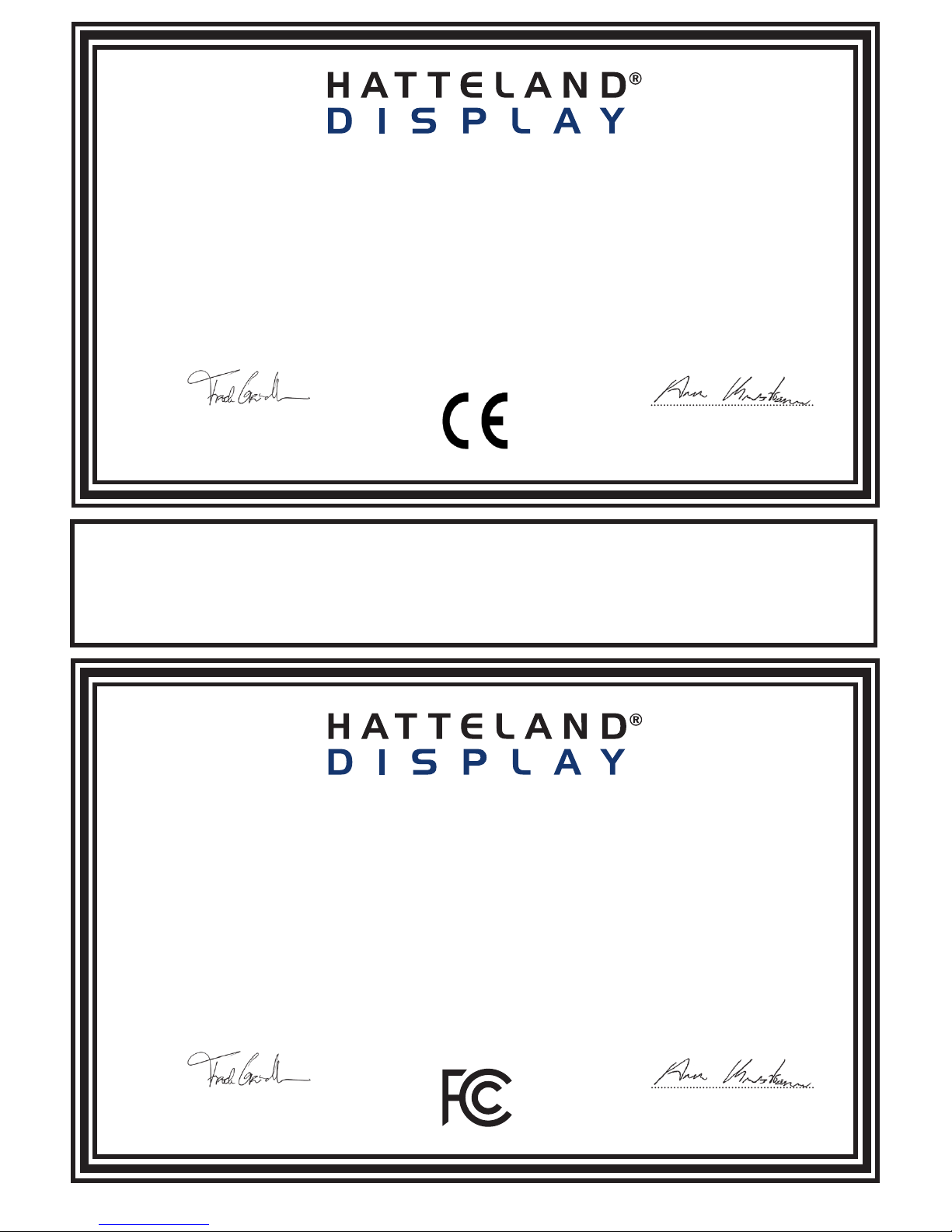
IND100237-1
Declaration of Conformity
We, manufacturer, Hatteland Display AS, Åmsosen, N-5578 Nedre Vats, Norway
declare under our sole responsibility that the
JH MMD, JH MMC, JH STD, JH MIL, HM NMD, HM MIL, HM CMD, HT STD, HD MMD, HM MMD, HT MMC
and HD MMC product ranges is in conformity with the following standards in accordance with the EMC Directive.
Low Voltage Directive 2006/95/EC
EN 60950
EMC Directive 2004/108/EC
EN 55022 Class A
EN 55024
Signature:........................................................
Frode Grindheim
Vice President Product Management
Nedre Vats, Norway
CE MARK FIRST AFFIXED DATE (11 March 2010)
Signature:........................................................
Arne Kristiansen
Site Manager - Test & Commission Division
Oslo, Norway
Declaration of Conformity
We, manufacturer, Hatteland Display AS, Åmsosen, N-5578 Nedre Vats, Norway
declare under our sole responsibility that the products listed below comply with
FCC 47 CFR Part 15, Subpart B, Class A:
JH MMD, JH MMC, JH STD, JH MIL, HM NMD, HM MIL, HM CMD,
HT STD, HD MMD, HM MMD, HT MMC and HD MMC product ranges.
Note: This equipment has been tested and found to comply with the limits for a Class A digital device, pursuant to part 15 of the FCC Rules.
These limits are designed to provide reasonable protection against harmful interference when the equipment is operated in a commercial
environment. This equipment generates, uses, and can radiate radio frequency energy and, if not installed and used in accordance with the
instruction manual, may cause harmful interference to radio communications. Operation of this equipment in a residential area is likely to
cause harmful interference in which case the user will be required to correct the interference at his own expense.
Signature:........................................................
Frode Grindheim
Vice President Product Management
Nedre Vats, Norway
FCC MARK FIRST AFFIXED DATE (16 February 2012)
Signature:........................................................
Arne Kristiansen
Site Manager - Test & Commission Division
Oslo, Norway
Declaration of Conformity
We, manufacturer, Hatteland Display AS, Åmsosen, N-5578 Nedre Vats, Norway
declare under our sole responsibility that the JH MMD, JH MMC, JH STD, JH MIL, HM NMD, HM MIL, HM CMD, HT STD,
HD MMD, HM MMD, HT MMC and HD MMC product ranges is in conformity with IEC 60945 4th (EN 60945:2002) and IACS E10
(where applicable)
Page 86
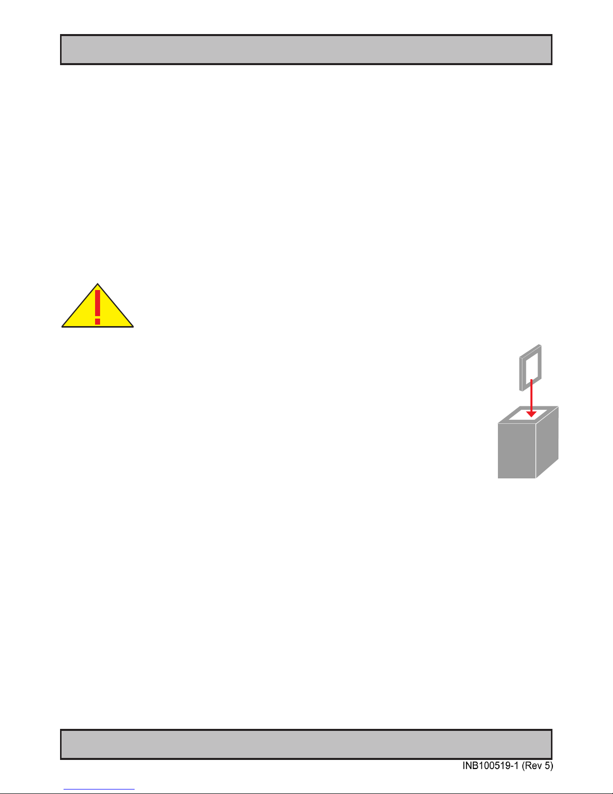
86
IND100077-14
Appendix
Return of goods:
(Applies not to warranty/normal service/repair of products)
Hatteland Display referenced as “manufacturer” in this document.
Before returning goods, please contact your system supplier before sending anything directly to manufacturer. When
you return products after loan, test, evaulation or products subject for credit, you must ensure that all accessories
received from our warehouse is returned. This applies to cables, powermodules and additional equipment except
screws or similar, user manual, datasheets or other written paper documents. Furthermore, the product must not have
any minor / medium or severe scratches, chemical spills or similar on the backcover, front frame or glass.
This is needed to credit the invoice 100%. Missing parts will not be subject for credit, and you will not get total credit
for returned product. You will either be charged separately or the amount is withdrawn from the credit. If you decide to
ship the missing items on the after hand, you will get 100% credit for that particular invoice or items received at
manufacturer incoming goods control. Please contact our service/sales department if additional questions
Return Of Goods Information
Make sure you surround the product with the following material (whenever possible):
Use the original packaging from manufacturer, rm foam material, bubble wrap, lots of PadPack paper
or foam chips/polyester wrapped in sealed plastic bags. Please make sure that the unit is protected
with a surrounding plastic bag to prevent dust accumulation around the unit.
If you do not have the original packaging or are uncertain how to secure the unit properly,
please consider seeking advice from nearby shipping or transportation ofces, if in doubt!
Do not under any circumstances use loose foam chips, expanded polyester, clothes, cardboard with
sharp edges/spikes, too little or nothing to secure the unit inside the box. Do not use cardboard
boxes that are clearly too weak or not suitable for securing the unit properly during overseas shipment.
Handling and packing units for return/credit
To prevent damage during shipping and transportation, respect the guidelines below.
Page 87
87
IND100077-7
Appendix
Terms
Terms Of Sale And Delivery
1) APPLICATION
The terms of sale and delivery apply for Hatteland Display.
2) PRICE
a) The price is per each, if nothing else has been stated, VAT not included. Price is based on the prices from our suppliers, current
custom rates, taxes, rate of exchange and international raw material prices. We reserve ourselves the rights to adjustments in case
of alternation on the above mentioned.
b) Included in the price is the supplier’s standard packing. In case of re-packing/smaller quantities we reserve ourselves the right to
add an additional sum for warrantable packing according to CECC 0015 (Basic inspection for protection of electrostatic sensitive
devices)
3) VALIDITY
If nothing else has been stated in our quotation, the offer is valid for 30 days from the date of quotation.
4) PACKAGE QUOTATION
A package quotation means that all the components offered, must be ordered by us. If one component or more are removed from the
quotation, the prices given in the package quotation are not valid.
5) TERMS OF PAYMENT
Cash on delivery or payment in advance. Net granted for companies, schools and institutions only, according to agreement. In case of
too late payment 1.5% interest/month will be charged. Seller has mortage rights in the goods delivered until the purchase price,
additional interests and charges have been paid in full. Accepted bill is not considered as payment until it has been honoured in full.
6) TIME OF DELIVERY
The quoted time of delivery is based on information from our suppliers. We disclaim any responsibility for the consequences of any
delay or cancellation from our suppliers. Belated delivery gives not solely the right for cancellation.
7) DELIVERY POINT OF TIME
Goods are considered delivered to customer when handed over to charterer.
8) FREIGHT / PACKING / FORWARDING FEE
Hatteland Display AS charge NOK 50,- in forwarding fee for orders below NOK 1000,-.
Freight charge according to expenses for orders above NOK 1000,-. VAT not included.
9) COMPLAINT
By receipt customer must check goods for obvious defects which have to be claimed within 8 days from receipt. Otherwise acceptance
of complaint can not be counted on.
10) GUARANTEE / SERVICES
Time of guarantee is calculated from our date of shipment, and applies to the extent that we are covered by our supplier’s guarantee
regulations. The guarantee does no longer apply if:
I) there has been encroached upon the goods without seller’s consent
II)termsofpaymentisnotfullled
III) the goods have been damaged due to unskilled treatment
IV) components which are sensitive for static electricity have not been unpacked and treated in a secure way.
Minimum requirements: CECC 00015’s standards for handling of such components. The guarantee does not include fair wear and tear.
11) RESPONSIBLITY
Sellerundertaketodeliverfaultlessandfunctionalcapablegoodsaccordingtoexistingtechnicalspecications.Sellerdisclaim
responsibility for any damage or loss which directly or indirectly may be caused due to failure or defect with the delivered goods, if
carelessness from the seller can be limited up to the cost of the goods. The supplier’s responsibility for defects with the supplied
goods do not include secondary damage or loss.
Page 88

88
IND100077-7
Appendix
Terms
INSTRUCTIONS FOR THE CONSIGNEE
12) CANCELLATION / RETURN
Bindingsalescontractisconcludedwhenwehaveconrmedcustomer’spurchaseorder.Anydisagreementsinourorderconrmation
must be reported to seller within 6 days. The agreement can not be altered without our permission, after acceptance from our
supplier. If goods are wanted to be returned, a Return No must be assigned from seller. Returned goods without a Return No will not
be accepted. By return of stock listed goods, 20% return fee is charged. Returned goods are shipped on customer’s account and risk.
13) LOAN, RENT and DEMO
When borrowing of goods for demo/test, the date of return must be added to the document. If no date has been stated, date of
return is two weeks from the date of the document. Before return, seller must be contacted for a Return No (RTK). Goods which have
been sold with an agreed right of return within stated terms, shall also have a Return No. The Return No must be obtained before the
stated date of return. Returned goods without a Return No, or which have not been packed in original packing, will not be accepted.
14) LIMITATIONS
If any of our suppliers claim limited delivery terms towards us, our terms of delivery will be restricted according to those.
15) SOFTWARE
Sold or borrowed software is not allowed to be copied or spread in other ways, without a written permission.
16) RE-EXPORT
Goods delivered from seller may be subject to special rules of exportation in their supplier’s native country. Buyer is responsible to obtain
necessary permissions for further export/re-sale.
17) QUESTION IN DISPUTE
To settle any dispute the Karmsund Herredsrett is approved the legal venue.
1) CONTROL
Control the goods immediately by receipt. Examine the quantity towards the invoice/packinglist/shipping documents. Look for outward
defects on the packing which may indicate damage on or loss of contents. Control the container and the seals for any defects.
2) SECURING EVIDENCE
When defects on the goods have been found, evidence must be secured, and seller must be informed. Call the transporter and point out the
defects. Add a description of the defects on the goods receipt, the forwarder’s copy of the way-bill or on the driving slip.
3) RESCUE
Bound the damage. Try to restrict the damage and the loss. Seller will compensate expences incurred due to reasonable security efforts in
addition to damage and loss.
4) COMPLAINT
Write immediately a complaint to the transporter or his agent. Forward immediately the complaint to the transporter or his agent, and hold
the transporter responsible for the defects. The complaint must be sent at the latest:
- for carriage by sea: within 3 days
- for overland / air transportation within 7 days
5) DOCUMENTATION
For any claims the following documentation is required, and must be forwared to the company or their agent: invoice, way-bill and/or bill of
landing, and/or statement of arrival, inspection document, besides a copy of the letter of complaint to the transporter.
Page 89
89
IND100351-2
Appendix
Pixel Defect Policy
PIXEL DEFECT POLICY
Dot-defects (Bright or dark spots on the panel)
Due to the effect that dot failures are part of the TFT technology such failure occurrence cannot be prevented basically. Even though
dot defects usually occur during production process, new defects can appear within the lifespan of a TFT display. Neither the production
at LCD-supplier nor the use of a LCD-Monitor after shipment can be inuenced by Hatteland Display. Hence Hatteland Display cannot be
made responsible for such dot failures. However Hatteland Display understand and accepts the responsibility towards the customers for
the delivery of new displays, therefore accepts a limitation on dot defect’s occurrence on new displays delivered to the customer.
PRINCIPLES
a. One pixel consists of 3 dots (Red, Green and Blue)
b. Dot defects are differentiated between:
• Bright dot defects: Spot on the panel appear as pixels or sub pixels that are always lit. Non-extinguishing dot.
• Dark dot defects: Spot on the panel appear as pixels or sub pixels that are always dark (off). Non-lightening dot.
c. Inspector observes the LCD from normal direction at a distance of 50cm above the worktable. Dark dots are counted
under entire white screen. Bright dots are counted under entire black screen.
d. Dot failures within tolerances below do not qualify for warranty claims.
PIXEL DEFECT TOLERANCES
Bright dot
≤ 4 dots
Two adjacent bright dots * ≤ 2
Distance between 2 dot defects * ≥ 15mm
Dark dots ≤ 8
Total number of bright or dark dot defects. * ≤ 8
* 1 or 2 adjacent dot defects considered as 1 defect.
EXTRAORDINARY CIRCUMSTANCES
Possible cases which cannot be inuenced either by customer or Hatteland Display.
Examples for extraordinary circumstances:
• Allocation from LCD-Supplier
• Outstanding high number of LCD-panels with bright dots but within LCD-suppliers Specication.
• Sharply increased demand by customer
In such cases a mutual agreement is inevitable.
Examples:
• Acceptance of bright dots in “non-critical” display areas.
• Acceptance of bright dots with dened color.
Last Revised July 2007
Page 90
90
IND100077-112
Appendix
Notes
General Notes:
- The unit is type approved according to EN60945 4th, 4.4, equipment category b) protected from the weather.
- Other type approvals applies for the different products.
Please see the appropriate “Specications” page in this manual for more information.
- Use of brillance and Glass Display Control™ (touch key functions) may inhibit visibility of information at night.
Note for units equipped with an PCTS (Projected Capacitive) Touch Screen:
For Maritime Multi Display (MMD) / Industrial Standard Display (STD) units the touch screen signals are routed through
the display unit via the USB port and can not be controlled / detect status by the unit itself in any way. It means that even
if the unit was turned off by the front bezel Power ON/OFF function, the touch screen is still active and it will still send
touch screen signals through the pipeline.
This can be an issue to consider when you are cleaning the front glass. In order to avoid sending touch screen signals,
you have to either physically cut power to the unit, making sure that no lights illuminate, or disconnect the USB cable
physically from either computer or display unit. You may also disable the touch screen functionality from within the
Operating System (OS) or via customized functions from within applications running on the external computer you have
connected.
Maritime Multi Computer (MMC, Panel Computer) uses internal USB connection and can be controlled by the Operating
System (OS). So, in order to clean the glass without any touch screen movement beeing detected, you either have to
shut down the Operating System (either via customized functions from within applications or by touching the Power On/
Off symbol) to make sure the unit has been shut down before attempting to clean the glass surface.
To learn more about how to properly clean glass surfaces, review the “Ergonomics” section in the “General Installation
Recommendations” chapter earlier in this manual.
Page 91
91
IND100077-24
Appendix
User Notes
Page 92
92
Appendix
IND100077-118
Rev. By Date Notes
00 -1 BUSE15 Feb 2012 Release for internal review.
01 ALL
BU
SE
17 Mar 2012 Revised after internal review.
02 ABSE20 Apr 2012 Revised Console Mount Kit+Table Mount Bracket typenumbers (page 6,16,17,52,53,54,55,56,57,68,69,70,71)
Replace MMC drawing with MMD/STD drawing (page 69,70)
03 BU
AK
SE
16 Aug 2012 Added text for MADI, DCDi functions, page 35,36
Revised type approvals, page 54,55,56,57,58,59
04 AB
BU
SE
13 Nov 2012 Revised minor text elements throughout manual where needed
Revised Contents of Package (Console Mounting kit now part of standard factory delivery), page 5
Added note about Full/Half duplex, page 79
05 BUSE10 Jan 2013 Added point 1. to Ergonomics section, cleaning of glass, page 12
Added Installation procedures for HD TMB SX1-C1 and HD 19BRD SX1-A1, page 18,19,20
Added new functions: “OSD Lock mode/Full Mode” and “OSD Key Outdoor”, page 32,45,46,47
- Reference to ECN: http://www.hatteland-display.com/mails/01_2013_ecn.html
Revised text for “OSD Mode/Full”, note #2, concerning power off and on, reverts back to Simplied, page 46
Revised text for “LED Drive”, default is 0-31, not 0-100, page 51
Revised text for “GDC Sensitivty”, added caution how to reset this value via SCOM command, page 51
Added Mounting Bracket (BRD version 1) accessory typenumber for 12,15,17 inch, page 58,59,60
Added High Bright specications for 17 and 19 inch, page 60,61
Added note for PCTS (Projected Capacitive) Touch Screen, page 90
Revision History
Page 93
93
Revision History
Appendix
IND100077-118
Page 94

www.hatteland-display.com
 Loading...