

Page 1
Operating Manual
Mounting instruction
H129 V2
for the radio control system of the company
Serial number:
(Please fill in the serial numbers here:)
____________________________________________________________________________________________________________
Hatox GmbH • Geschäftsführer: Dipl.-Ing. Thomas Haug • Registergericht Mannheim HRB 700804 •
Ust-Id-Nr.: DE249790235
Page 1 of 19
Page 2

Chapter
content
0
Extent of supply
1
Safety instructions
2
General information
3
Safety features in the Hatox system
4
Functioning recheck
5
Optical check
6
Initial operation
7
Indication LEDs
8
Maintenance
9
Warranty
10
Safety
11
Source of danger
12
Safety measures in working area
13
Protective devices
14
Behavior in case of danger
15
Trouble shooting
16
Mounting instruction
17
Maintenance
18
Disposal
19
Technical data
20
Interface H 129V2
A
CAN protocol example
Table of contents;
____________________________________________________________________________________________________________
Hatox GmbH • Geschäftsführer: Dipl.-Ing. Thomas Haug • Registergericht Mannheim HRB 700804 •
Ust-Id-Nr.: DE249790235
Page 2 of 19
Page 3

0. Extent of supply
1 X H129V2 with Antenna socket and antenna
1. Safety instructions:
Even if you have worked with radio remote controls before, please read this operating
manual before initial operation carefully! Only this one contains the latest information for
your Hatox system and how to use it!
Please note in any case the respective working safety and protective precaution
instructions! Only instructed and authorized personnel may operate the Hatox system! The
safety features integrated in the Hatox system have to be checked on a regular basis.
In case of any failures the Hatox module has to be turned off at once. The modul has to
be deactivated via stop button (has to be connected directly to supply) . The connecting
cable has be disconnected from the stationary transceiver of the unit to be controlled.
Never operate a defective Hatox system!
Contact you distributor or Hatox directly!
Always stay in range of sight with the unit to be controlled!
Never trust the LCD display. The shown information may be wrong.
By neglecting this advice you jeopardize yourself or other persons! Hatox declines any
warranty or liability in this case! The radio system is only suitable for the control of
construction machinery and industrial equipment. Only there the applied safety measures
(STOP, zero position) are fully effective. A different use is not allowed and absolves Hatox
from any responsibility!
____________________________________________________________________________________________________________
Hatox GmbH • Geschäftsführer: Dipl.-Ing. Thomas Haug • Registergericht Mannheim HRB 700804 •
Ust-Id-Nr.: DE249790235
Page 3 of 19
Page 4

2. General information
The power supply of the radio control is provided in most of the case via the connecting
cable.
For machines that have never been operated with a radio control before, generally a
ground wire (neutral) has to be added. Otherwise the power supply to the Hatox
electronics cannot be set up!
Please mind that the operating voltage of the radio systems complies with the connecting
values of the unit to be controlled. The valid operating voltage is written down in the
enclosure.
Never expose the Hatox components to the harsh water jet of a high pressure cleaner!
The same applies for the transmitter!
The module may only be installed in an upright position to the outer wall of the switching
cabinet (the antenna shall always overlap the wall). It is important that the antenna is not
shielded by metal parts, neither partly nor totally.
The module shall always be installed in that manner that the antenna remains visible with
every position change of the transmitter.
When operating never disconnect the antenna from the stationary transceiver. This
worsens the quality of reception.
In case of service and maintenance work please disconnect the Hatox control completely
from the machine (including possibly an external antenna).
3. Safety features in the Hatox system
In the portable H153V2: stop button
In the stationary H129V2: stop output
In order to grant a fault-free operation please adhere exactly to the following rules for
operation: The machine can only be turned on (provided that the transmitter is ready for
operation) if no buttons and joysticks are operated.
____________________________________________________________________________________________________________
Hatox GmbH • Geschäftsführer: Dipl.-Ing. Thomas Haug • Registergericht Mannheim HRB 700804 •
Ust-Id-Nr.: DE249790235
Page 4 of 19
Page 5

4. Functioning recheck:
For keeping up the operating safety a regular functioning recheck of the Hatox radio
control is necessary. For daily one-shift operation we recommend this check at least once
per day or after every change of shifts. The check can be done by help of the LEDs on the
stationary unit/units. For that the transmitter has to be put in a ready-to-operate status.
5. OPTIcal check:
Before starting to operate please check if the transmitter shows any damages!
Please check if all protective devices are provided and in working order!
Never work with a unit that shows damages like that!
Have those defects fixed immediately!
6. Initial operation:
STOP-control: Press the stop push button connected with the module. Afterwards please
check if the machine is in stop status, i.e. if it is turned off. (Switch-off time depending on
application. Please check the time in the operating manual of the machine).
Additionally, please effect the testing procedures which are described in the manual
of the machine!
____________________________________________________________________________________________________________
Hatox GmbH • Geschäftsführer: Dipl.-Ing. Thomas Haug • Registergericht Mannheim HRB 700804 •
Ust-Id-Nr.: DE249790235
Page 5 of 19
Page 6
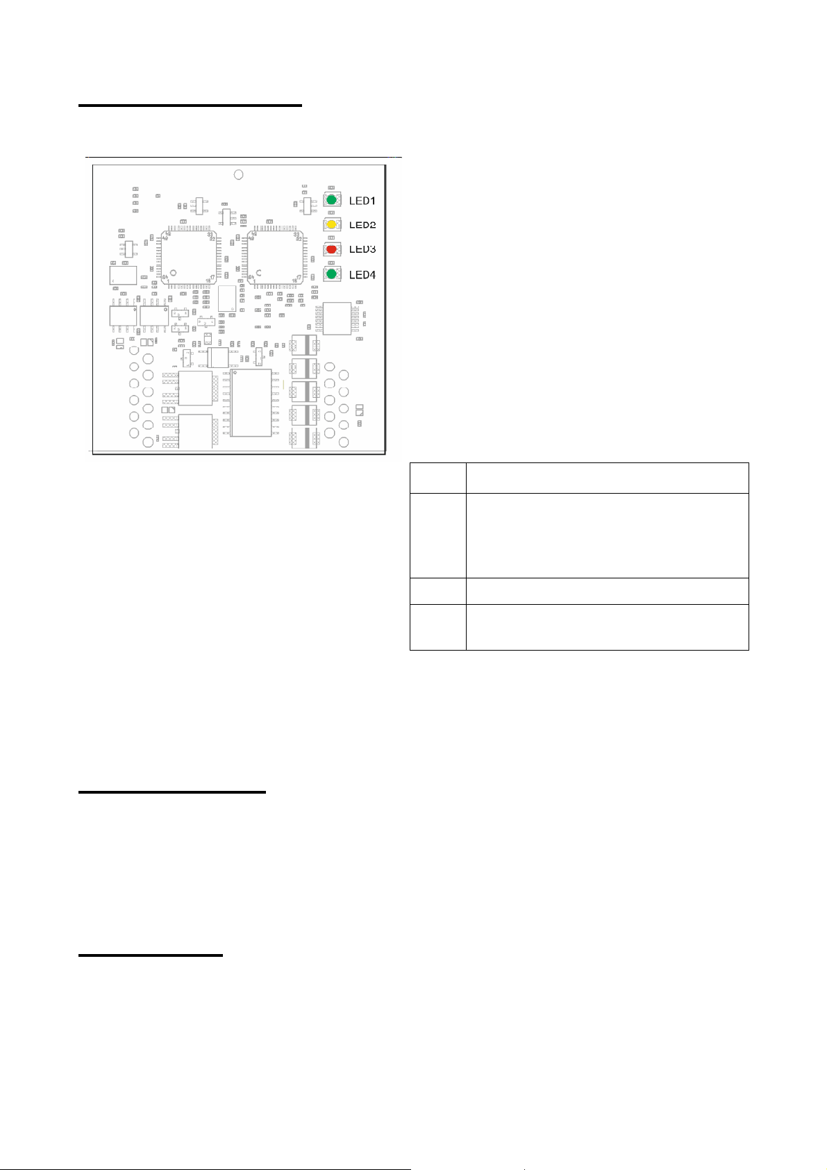
7. Indication LEDs
LED1:
POWER ON. Operating voltage
LED2:
CAN activity between controller and
stationary transceiver. Permanent
alluminating when the system is
turned on.
LED3:
Error
LED
4:
Radio: Irregular flashing shows that
the connection is not best.
Function of the LEDs at the H129V2:
8. Maintenance:
When doing electric welding at the machine to be controlled, the receiver has to be
disconnected from the power supply! Otherwise the receiver electronics is
endangered to be damaged!
9. Warranty:
We grant a warranty of 6 months on all Hatox radio remote controls (transmitter, receiver,
____________________________________________________________________________________________________________
Hatox GmbH • Geschäftsführer: Dipl.-Ing. Thomas Haug • Registergericht Mannheim HRB 700804 •
Ust-Id-Nr.: DE249790235
Page 6 of 19
Page 7

battery charger) from the date of sale on. In case of despatch to the manufacturer of the
machine please negotiate the warranty with the seller of the complete system. Special
conditions may exist.
Labor and material expenses are included in the warranty. Freight has to be taken over by
the buyer. Excluded from warranty are: Wear and tear parts, relays and batteries. The
warranty of functioning is not valid by damage, accident damage, neglect, incorrect use,
disobeying the operating instructions, not-adhering to the operating-, test- and service
advices as well as repairs or device changes not authorized by Hatox.
Hatox is not liable for indirect damages and reserves the right to decide for repair or
exchange.
____________________________________________________________________________________________________________
Hatox GmbH • Geschäftsführer: Dipl.-Ing. Thomas Haug • Registergericht Mannheim HRB 700804 •
Ust-Id-Nr.: DE249790235
Page 7 of 19
Page 8

10. Safety of this system:
This system is equipped with electronical safety features.
Interferences by other radio remote controls are excluded by an individual code for
each system.
WE THINK OF YOUR SAFETY !
Beware of incorrect operation or abuse. This can have consequences for your life, for
the machine or other material values.
The following persons may operate the Hatox control:
They have to be qualified and instructed acc. to the rules and regulations.
They have to obey this manual and also the manual of the machine to be controlled.
(SEE MANUAL OF THE MACHINE TO BE CONTROLLED)
The operator has to see to it that no unauthorized personnel gets hold of the radio control
once he has put it down (for a break etc.), e.g.:
by locking away the transmitter
by taking out the batteries
by taking out the stop key cap (if it exists)
The operator has to take care that
the user of the radio control has access to the operating manual
that the user has read and understood it
____________________________________________________________________________________________________________
Hatox GmbH • Geschäftsführer: Dipl.-Ing. Thomas Haug • Registergericht Mannheim HRB 700804 •
Ust-Id-Nr.: DE249790235
Page 8 of 19
Page 9

11. Source of danger
This system enables the wireless operation of machines. The transmission of control
commands is effected, however also outside the range of vision and through or around
obstacles.
THEREFORE YOU SHOULD:
Put the transmitter always at a safe and dry (locked) place which is not accessible to other
persons.
Always turn off the transmitter when it is not in use.
Before installation, repair or maintenance power supply has to be disconnected.
When welding please be sure that both the power supply and every antenna connection
(e.g. to a separate antenna) is disconnected.
12. Safety measures in working area
Ensure a stable position
Make sure that nobody stands in the slewing or working area during (initial) operation
Always use the waist belt / hand strap of the transmitter as far as it is provided
13. Protective Devices
The radio control turns in idle position
by pressing the red stop button in the control panel of the transmitter
when leaving the range
by an error of the transmitter or the stationary receiving or controlling unit
by taking out the batteries
when the capacity of the batteries is too low
These protective devices are provided for the safety of persons and material assets and
must in no way be removed or bypassed !!!
Additional protective devices are depending on design.
Hatox recommends:
protective collar / safety bar
lower positioned control elements
These devices protect the control elements from unwanted operation and therefore from
unintended commands.
____________________________________________________________________________________________________________
Hatox GmbH • Geschäftsführer: Dipl.-Ing. Thomas Haug • Registergericht Mannheim HRB 700804 •
Ust-Id-Nr.: DE249790235
Page 9 of 19
Page 10
14. Behavior in case of danger
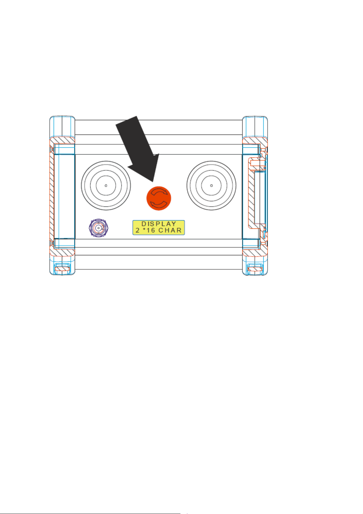
Hatox recommends strongly to use an e-stop-switch. In case of an emergency
immediately press the red stop button in the control panel of the transmitter. For the
further procedure adhere to the operating manual of the machine to be controlled.
____________________________________________________________________________________________________________
Hatox GmbH • Geschäftsführer: Dipl.-Ing. Thomas Haug • Registergericht Mannheim HRB 700804 •
Ust-Id-Nr.: DE249790235
Page 10 of 19
Page 11

15. Trouble shooting:
Appearing Error
Possible causes
Trouble shooting
System cannot be put into
operation
System is not locked in yet (is
shown by „SCAN“ on the display)
After turning on wait up to 5 sec.,
until „STOP“ is shown on the
display. Then activate On/Horn. As
soon as „RUN“ is shown in the
display, the system is activated.
System cannot be put into
operation, no display indication
batteries empty
Insert new or recharged batteries
Battery or battery shaft is defect,
e.g.
contact corrosion
battery leaked
Check if the same effect happens
with a different pair of batteries. If
not, dispose the batteries in a
proper manner and replace them
by new ones.
In case that the contacts are
corroded, have them cleaned by a
person skilled in this.
Period of operating is too short.
Wrong or discharged batteries
were inserted.
Check if the power supply of the
battery charger was disconnected
or if the connection was not
properly made.
The transmission of control
commands to the machine is
disturbed.
No radio connection
Check the function of the LEDs at
the stationary transceiver (see
above).
Check the installation of the
stationary transceiver. There
should be intervisibility to the
antenna.
Install the stationary tranceiver as
described above!
Stationary transceiver resp. the
antenna of the transceiver is built in
a metal cabinet, a vehicle or in the
machine to be controlled.
Install the stationary tranceiver as
described above!
Individual functions cannot be
controlled.
Interruption of the control cable
resp. individual cables between the
machine to be controlled and the
stationary transceiver or the
stationary controller.
Check the plug for tight
connection, good contact etc.
Check the wiring in the switch
cabinet, connector, etc.
____________________________________________________________________________________________________________
Hatox GmbH • Geschäftsführer: Dipl.-Ing. Thomas Haug • Registergericht Mannheim HRB 700804 •
Ust-Id-Nr.: DE249790235
Page 11 of 19
Page 12
16. Mounting instruction
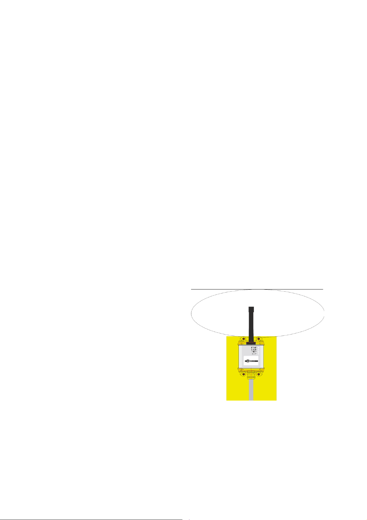
Only install the stationary transceiver
vertically on a outer wall of the object to
be controlled (The antenna should
always rise up over the wall). It has to be
ensured that the antenna is not shielded
by metal parts, neither partly nor totally.
Connecting instructions and initial operation.
The connection to the machine may only be done by an authorized expert who is
familiar with the machine!
There are following additional installation instructions:
For any work at the machine and at the Hatox system the stationary unit/s have to be
switched off the power.
The VDE-specifications as well as the local EVU-regulations and the accident
prevention guidelines (UVV) strictly have to be observed.
Hatox does not takes over any responsibility, liability and warranty for any possible
personal injury, damage to property and consequential loss which result from inproper
or reckless use of this system or which contravene the regulations, which this operating
instruction, the operating instruction and the general regulations of the machine to be
controlled are base on.
It has to be seen to it that the stationary transceiver unit is installed at a well accessible
position and not in the object to be controlled.
Generally switch the machine to be contolled off the power before you connect the
Hatox system.
Installation of the transceiver:
____________________________________________________________________________________________________________
Hatox GmbH • Geschäftsführer: Dipl.-Ing. Thomas Haug • Registergericht Mannheim HRB 700804 •
Ust-Id-Nr.: DE249790235
Page 12 of 19
Page 13

17. Maintenance:
The operator has to take care that the devices of the wireless control are checked on a
regular basis – at least however once per year by an authorized person (specialist).
A specialist is a person who has sufficient knowledge in wireless controls and machine
controls in general as well as in the area of the individual machine to be controlled due
to his special education and experience. He has to be familiar with the relevant
governmental labor protection laws, accident prevention regulations, regulations and
general accepted rules of technics (such as DIN-standards, VDE-regulations,
regulations of the mutual indemnity society, EU-standards, technical regulations of
other member countries of the European Union or other states of the agreement of the
European Economic Area).
He has to be familiar with the work-safe state of the devices for the wireless
transmission of control commands.
18. Disposal
Avoid pollution.
Electronic pieces and parts of it are hazardous waste!
This applies especially for rechargeable batteries.
Instruct a specialist with the material processing and disposal.
Save the environment! Use rechargeable batteries only. Avoid the use of standard
batteries (non-rechargeable) !
____________________________________________________________________________________________________________
Hatox GmbH • Geschäftsführer: Dipl.-Ing. Thomas Haug • Registergericht Mannheim HRB 700804 •
Ust-Id-Nr.: DE249790235
Page 13 of 19
Page 14

19. Technical data:
Storage temperature:
-40° C to + 80° C
Operating temperature:
-20° C + 70° C
Protection class (not valid for battery charger):
Depending on assembling
Frequency range
902-928 MHz
Baud rate:
4800 baud (bits per sec.)
Range:
50 up to 500 meters (depending on installation and
environment)
Power supply of the portable unit:
2 * 1,2 V NiMh- battery (AA)
Power supply of the stationary unit:
6 – 36 V DC
Outputs stop:
Max. 36 V DC / 1,2 A
____________________________________________________________________________________________________________
Hatox GmbH • Geschäftsführer: Dipl.-Ing. Thomas Haug • Registergericht Mannheim HRB 700804 •
Ust-Id-Nr.: DE249790235
Page 14 of 19
Page 15
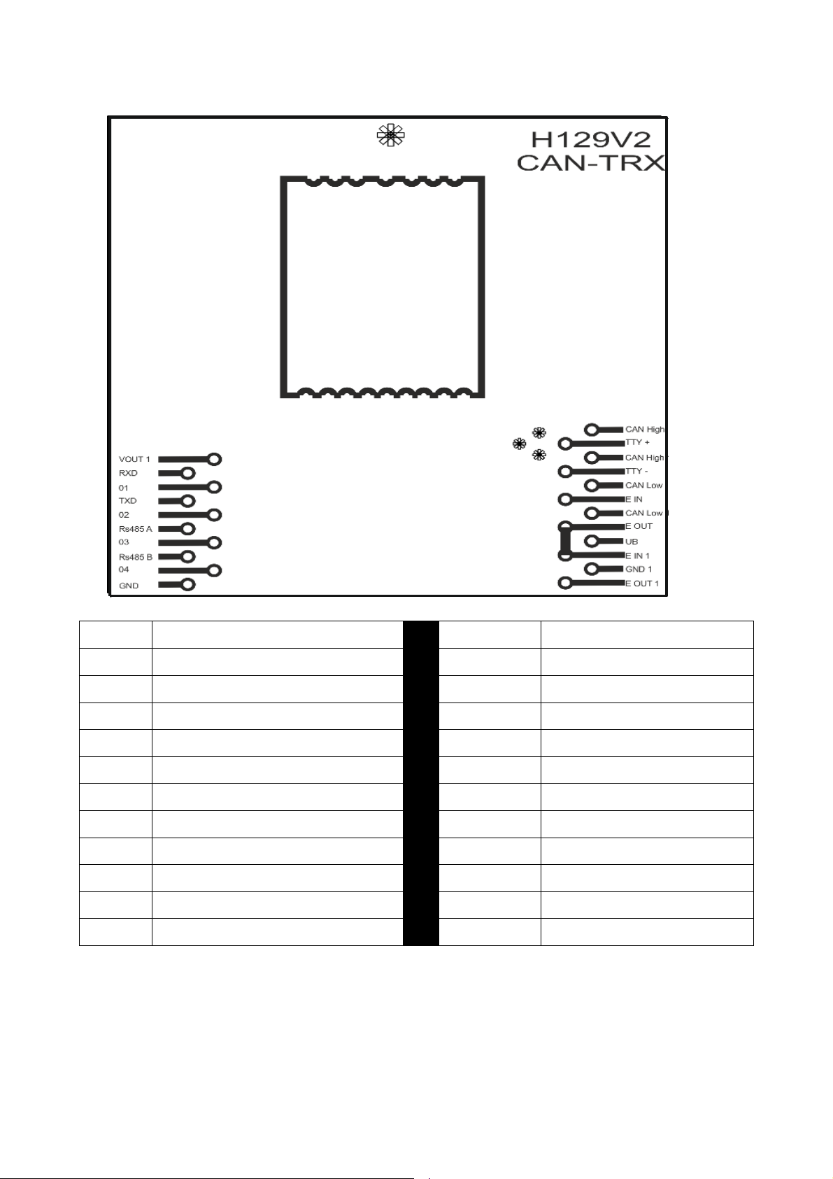
20. INTERFACE H129V2
CAN High 1
CAN High 1
TTY +
Serial Interface
VOUT1
Supply for Outputs 6- 36 V DC
CAN High 2
CAN High 2
RXD
RS232 serial Interface RECEIVE
TTY-
TTY -
1
Output 1
CAN Low 1
CAN Low 1
TXD
RS232 serial Interface TRANSMIT
EIN
Stop-Input / 6-36 V DC
2
Output 2
CAN Low 2
CAN Low 2
RS485A
RS485 serial Interface -A
EOUT
Stop-Output
3
Output 3
UB
Supply 6- 36V DC
RS485B
RS485 serial Interface -B
EIN 1
Stop-Input 1 / 6-36 V DC
4
Output 4
GND
Ground
GND
Ground
EOUT 1
Stop-Output 1
____________________________________________________________________________________________________________
Hatox GmbH • Geschäftsführer: Dipl.-Ing. Thomas Haug • Registergericht Mannheim HRB 700804 •
Ust-Id-Nr.: DE249790235
Page 15 of 19
Page 16

Enclosure A
EXAMPLE FOR CAN PROTOCOL
Generally:
Baudrate: 125kBaud
Node-No.: 0x64 (100dez)
Mode: Can-Open-Slave
PDO’s:
Msg: Id: Data: Function:
TPDO1 0x1E4 Dat0 | Dat1 | Dat2 | Dat3 | Dat4 | Dat5 | Dat6 | Dat7 Analog
TPDO2 0x2E4 Dat0 | Dat1 | Dat2 | Dat3 | 0x00 | 0x00 | 0x00 | Dat7 Digital
RPDO2 0x364 Dat0 | Dat1 | Dat2 | Dat3 | Dat4 | Dat5 | Dat6 | Dat7 Display Text
Transmit PDO1 (Analog):
Dat0 = ANA1 – (0x00 – 0x7F – 0xFF) - Joystick right up/down (up=0xFF down=0x00)
Dat1 = ANA2 – (0x00 – 0x7F – 0xFF) - Joystick middle up/down (up=0xFF, down=0x00)
Dat2 = ANA3 – (0x00 – 0x7F – 0xFF) - Joystick left up/down (up=0xFF, down=0x00)
Dat3 = ANA4 – (0x00 – 0x7F – 0xFF) - not used (0x7F)
Dat4 = ANA5 – (0x00 – 0x7F – 0xFF) - not used (0x7F)
Dat5 = ANA6 – (0x00 – 0x7F – 0xFF) - not used (0x7F)
Dat6 = ANA7 – (0x00 – 0x7F – 0xFF) - not used (0x7F)
Dat7 = ANA8 – (0x00 – 0x7F – 0xFF) - not used (0x7F)
Transmit PDO2 (Digital):
Dat0 => Bit0: Emergency stop
Bit1: Enable
Bit2: Zero position
Bit3: MRC
Bit4: Winch
Bit5: ODS
Bit6: DS
Bit7: Support Ramp
Dat1 => Bit0: Headrest Ramp
Bit1: ---
Bit2: ---
Bit3: ---
Bit4 ---
Bit5: ---
Bit6: ---
Bit7: ---
Page 17

Dat2 => Bit0: Teachmode
Bit1: -- Bit2: ---
Bit3: ---
Bit4: ---
Bit5: ---
Bit6: ---
Bit7: ---
Dat3 => Bit0: ---
Bit1: ---
Bit2: ---
Bit3: ---
Bit4: ---
Bit5: ---
Bit6: ---
Bit7: Emergency Stop
Dat4 0x00
Dat5 0x00
Dat6 0x00
Dat7 => Bit0: Emergency Stop
Bit1: no data receiving
Bit3-2: „00“ receive quality 0%
„01“ receive quality <20%
„11“ receive quality 20 – 60%
„10“ receive quality 60 – 100%
Bit7-4 “0000” no joystick error
“0001” joystick error ANA1
“0010” joystick error ANA2
“0011” joystick error ANA3
“0100” joystick error ANA4
“0101” joystick error ANA5
“0110” joystick error ANA6
“0111” joystick error ANA7
“1000” joystick error ANA8
“1111” different errors available
Receive PDO2 (Text Display):
Dat0 xx – Line
Dat1 yy – Column
Dat2-7 6 chars in ascii code
1 line with 16 chars
Example:
ID: Data: Describtion:
0x364 0x01 | 0x01 | 0x48 | 0x41 | 0x54 | 0x4F | 0x58 | 0x20 „HATOX“
Page 18

Information to the user
Note: This equipment has been tested and found to comply with the limits for a Class A
digital device, pursuant to part 15 of the FCC Rules. These limits are designed to provide
reasonable protection against harmful interference when the equipment is operated in a
commercial environment. This equipment generates, uses, and can radiate radio
frequency energy and, if not installed and used in accordance with the instruction manual,
may cause harmful interference to radio communications. Operation of this equipment in a
residential area is likely to cause harmful interference in which case the user will be
required to correct the interference at his own expense.
Changes or modifications not expressly approved by the party responsible for compliance
could void the user's authority to operate the equipment.
This device complies with part 15 of the FCC Rules and with Industry Canada licenceexempt RSS standard(s). Operation is subject to the following two conditions: (1) This
device may not cause harmful interference, and (2) this device must accept any
interference received, including interference that may cause undesired operation.
Le présent appareil est conforme aux CNR d'Industrie Canada applicables aux appareils
radio exempts de licence. L'exploitation est autorisée aux deux conditions suivantes : (1)
l'appareil ne doit pas produire de brouillage, et (2) l'utilisateur de l'appareil doit accepter
tout brouillage radioélectrique subi, même si le brouillage est susceptible d'en
compromettre le fonctionnement.
Integration of Module
The Grantee is required to ensure equipment authorisation of the end product, which
includes the module, under all operating conditions and modes.
Label
End products shall bear a permanent label on which module certification numbers is
displayed. The certification number shall be preceded by the text: “Contains:”, so it
appears as follows:
Contains FCC ID: FCC ID of the module
or
Contains IC: IC certification number of the module
Users Manual
The users manual of the end product needs to include the following information:
Changes or modifications not expressly approved by the party responsible for
compliance could void the user's authority to operate the equipment.
Page 19
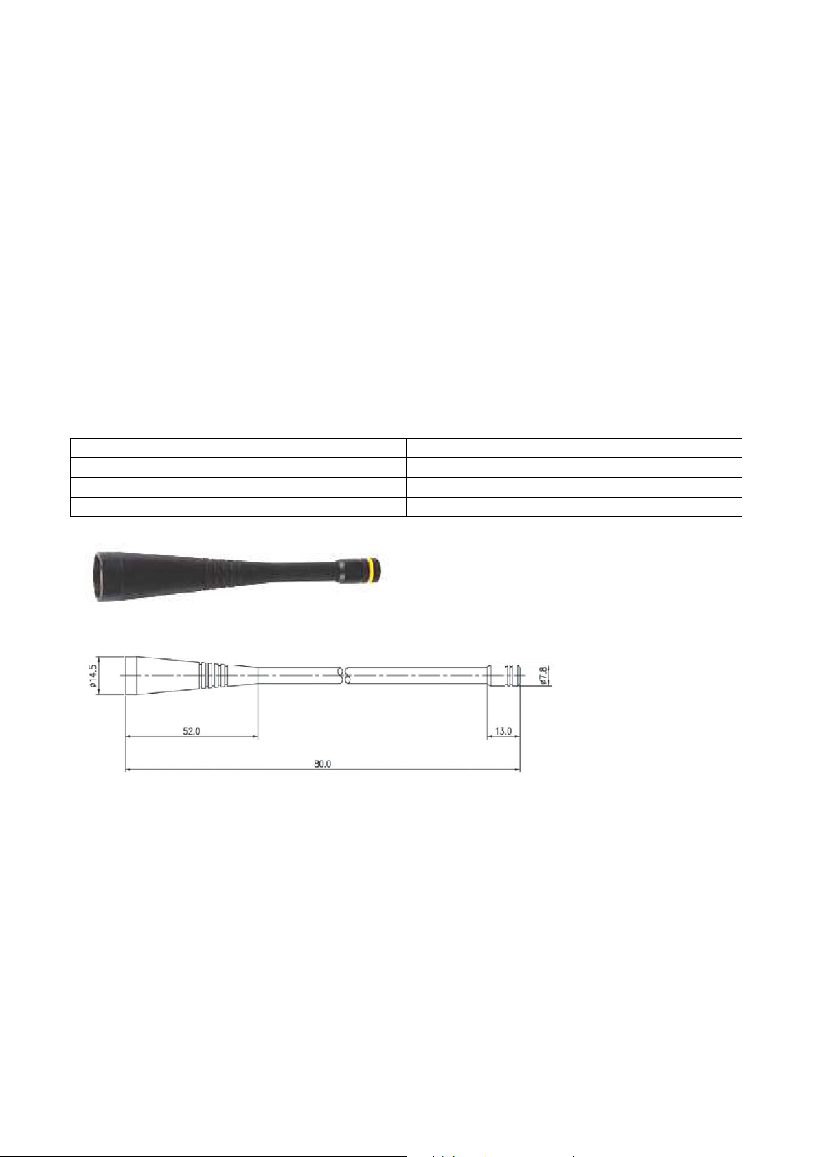
Frequency
915 MHz
Typ
Peitsche Lambda/4
Connector
R-SMA
Gain
0 dBi
This device complies with part 15 of the FCC Rules and with Industry Canada licenceexempt RSS standard(s). Operation is subject to the following two conditions: (1)
This device may not cause harmful interference, and (2) this device must accept any
interference received, including interference that may cause undesired operation.
Le présent appareil est conforme aux CNR d'Industrie Canada applicables aux
appareils radio exempts de licence. L'exploitation est autorisée aux deux conditions
suivantes : (1) l'appareil ne doit pas produire de brouillage, et (2) l'utilisateur de
l'appareil doit accepter tout brouillage radioélectrique subi, même si le brouillage
est susceptible d'en compromettre le fonctionnement.
RF Exposure
According to the low output power of the device, the module is allowed to be used in
portable application.
Approved Antennas:
 Loading...