

Page 1
Original / Authorized Agent Stamp
Product Serial Number:
Purchase Date:
* To ensure your warranty validation, please place your agent's stamp in the box and fill in the purchase date. If the
agent stamp and purchase date cannot be supplied, the warranty period will based on the manufacturing date of
the product.
Download File
www.uprtek.com
uSpectrum PC Software
User Manual
HATO ONE
HATO Agricultural Lighting
T. +31 (0)46 4585050
https://www.hato.lighting
Handelsstraat 31 (Handelsstraat 29 visitor address)
6135 KK Sittard The Netherlands
Page 2
Introduction
1
System Overview
3.1 Main Page
3.2 Measurement Modes Introduction
3.3 Measurement Introduction
3.4 Measurement Setting Introduction
3.5 Continuous Measurement Introduction
3.6 Customizing BASIC Mode List
3.7 Instruction of Spectrum Mode
3.8 FLICKER Mode Introduction
3.9 FREQUENCY Mode Introduction
3.10 ANALYSE Mode Introduction
3.11 CRI Mode Introduction
3.12 Switch Between CIE1931 & CIE1976
3.13 Compare Mode Introduction
3.16 Connecting with Mobile APP
3.17 Connecting with uSpectrum
3
Preparations before Use
2.3 System Reset
2
......................................................... 04
.
................................................. 18
......................................................... 19
.................. 21
.............................. 22
................. 23
......... 26
.......................... 27
........................ 28
............................. 29
...................... 30
........................ 31
.................................. 32
............. 34
........................ 35
3.14 BROWSER Mode Introduction
....................... 36
3.15 Transferring Data with PC Connection
.......... 37
.......................... 38
Specification
4.1 Product Specification
4.2 Product Appearance and Dimension
4
Appendices
5.1 Product Warranty Terms
5.2 Measurement Indexes
5.3 Q&A
5
......................................................... 42
........................................ 43
............... 45
.......................... 39
........................................................... 48
.................................. 49
....................................... 53
.................................................................. 59
To get more information related to operation, firmware upgrade
and warranty terms; online application for correction and Repair
service, please contact [email protected]
- 1 - - 2 -
............................................. 05
............................... 06
............................ 07
...................... 07
................................ 08
...................................... 09
........................................ 13
.................................................... 14
1.1 Packing Contents
1.2 Appearance Introduction
1.3 Annual Product Calibration
1.4 Product Notes and Precautions
2.1 Preparing Before Use
2.2 Basic Measurement
Contents
Page 3

1
- 3 - - 4 -
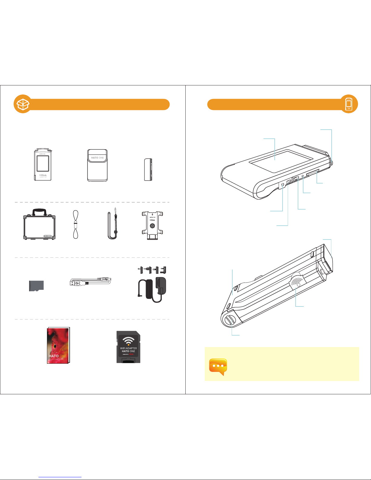
1.1 Packing Contents
1.2 Appearance Introduction
1.3 Annual Product Calibration
1.4 Product Notes and Precautions
Introduction
Page 4
- 5 - - 6 -
If the system crashes, please press the power key for 3
seconds to turn off the system.
If the problem still can’t be fixed, please use a pin to
press the reset key to turn off the system.
1.2 Appearance Introduction
Sensor Cover
Capture Key
Battery Cover
SD Card Slot
Power Key
Reset Key
Mini USB
Power Jack
Battery
3.5” Touch Screen
Strap Hole
1.1 Packing Contents
SD card
HATO ONE
spectro- gallilux meter
( It is used to connect with PC software.)
User manual
Please check HATO ONE spectro- gallilux meter packing
before use, contact your agent if there are missing items.
WiFi Wing
wireless remote control card
( It is used to connect with APP.)
Strap Neck Strap
Battery
USB Cable
Power Adaptor
Protection Bag
Case
Stand Bracket
User Manual
Page 5

2
- 7 - - 8 -
As the product is a high-precision instrument, please use it cautiously.
To ensure the accuracy of measurements, annual calibration is recommended.
Please consult the customer service department for the calibration service:
[email protected]
HATO ONE spectro- gallilux meter is a high-precision instrument. Please
unpack with care. Any vibration or collision may cause instrument damage.
If the product doesn’t work normally or needs repair, please don’t
attempt any repairs. All repairs must be performed by the authorized
customer service agent.
Most LCD screens have a very small and inconsequential defective pixel
rate (usually less than 0.1%). This results in occasional pinpoints of white
or other colors but will not affect the accuracy of measurements.
1.
2.
Precautions / Warnings
Please read the following precautions to avoid fire, excessive heat, chemical
leakage and explosion :
◆ Do not disassemble or modify the battery.
◆ Do not expose the battery to heat (fire) or water/moisture.
◆When disposing used/old batteries, wrap with insulation tape to shield the battery from
electrical contact with metallic objects, which might ignite a fire or explosion.
◆If the unit is plugged into the power adapter and the battery seems to be overheating, or if
there is smoke or peculiar odors emanating from the unit, unplug immediately to avoid the
possibility of fire.
◆However, do not touch the cables if there is heat emanating from near the cables as melted
or deformed cables could expose wiring and result in burns or electric shock.
◆Do not use cloth or anything to wrap or cover the equipment while charging – this could
cause the unit to overheat, melting the casing or causing fire.
◆If the unit is accidently immersed in water, or if moisture has seeped inside, or metal objects
have dropped into the casing, immediately remove the battery to avoid fire or electric shock.
◆Do not operate or store the battery in high-temperature environments-it will cause battery
leakage and/or shorten the life of the battery .
◆Do not use paint thinner, benzene or other organic solvents to clean the equipment – this
may damage the exterior finish or touch screen, and may even ignite fire.
1.3 Annual Product Calibration
1.4 Product Notes and Precautions
Preparations before Use
2.1 Preparing Before Use
2.2 Basic Measurement
2.3 System Reset
Page 6

- 9 - - 10 -
2.1 使用前準備
3
2
1
2.1 Preparing Before Use
Battery installation:
Step1. Hold HATO ONE, then press the battery cover.
Step2. Press the battery cover down to remove it.
Step3. Install the battery after removing battery cover.
※ Press the battery cover down then you can remove the
cover smoothly from HATO ONE.
1. Please charge the battery for 6 hours at first time usage.
2. To avoid any interruption while measuring, please check
battery status before use.
3. Please purchase a new battery if it gets low easily after being
fully charged, which means battery life comes to an end.
4. Usage time will depends on battery life, HATO ONE
battery can operate 5 hours after being fully charged.
2
1
Battery charging:
1. Plug power charging cable into power jack to start charging.
2. Power Off Status: Users can check power key, it will light in red while
charging and light off after being fully charged.
3. Power On Status: Users can check HATO ONE screen, it will appear
a lightning symbol to indicate charging, and lightning symbol will
disappear after being fully charged.
※ The power key will light
up in red, and light off
after fully charged.
when charging and disappear
after being fully charged.
※ Lightning symbol will appear
2.1 Preparing Before Use
3
Page 7
- 11 - - 12 -
2.1 使用前準備 2.1 使用前準備
1
2
1
3
2
4
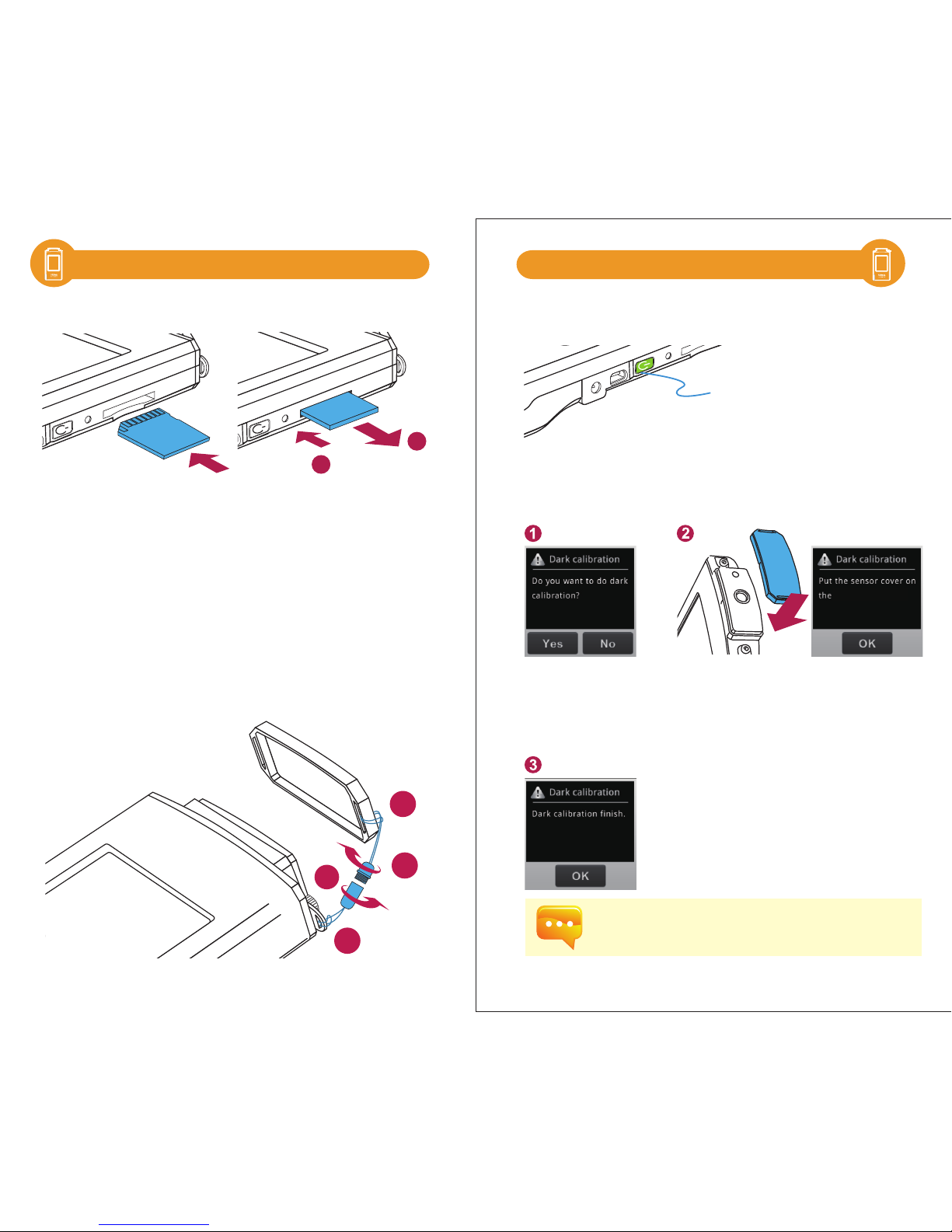
※ Press to remove the SD card
※ Insert the memory card
Installing the SD Card:
Remove the SD Card:
according to the direction.
Strap installation:
Step1. Unscrew the strap.
Step2. Tie the strap to the strap hole of HATO ONE.
Step3. Tie the strap to the sensor cover.
Step4. Screw the strap.
Press the Power button for 1 second and then release it.
※ When the power is on, the Power
button will turn on the green indicator.
When the power is off, the green
indicator will be off.
Power on
Dark calibration
When the system is powered on and the power key is in green, the screen will
show the Dark Calibration.
“
Do you want to
do dark calibration?”
Please select “Yes” .
After the sensor cover is put on,
please select “OK”.
When the screen shows “Dark calibration completed”,
please press “OK” to enter the main page.
It is recommended performing dark calibration every time
when it is powered on.
2.1 使用前準備
2.1 Preparing Before Use2.1 Preparing Before Use
HATO ONE.
Page 8

- 13- - 14 -
Set date and time
After the dark calibration is completed, please set date and time before
measurement.
Go to the next page.
Select “Option
”.
Select “Date” and
“
Time
”.
After the setting is
finished, please
press “Yes”.
After the setting is
finished, please
press “Yes”.
4 5
Please press the power key for 3 seconds to turn off the
system.
Measure
Select “Basic” to enter measurement page.
The measurement data
will be shown on the
screen after beep sound.
Press Capture key at
appropriate distance.
Point the sensor head at the target
light source.
Beep sound
while measuring
2.1 使用前準備 2.1 使用前準備
2.1 使用前準備
2.1 Preparing Before Use
2.2 Basic Measurement
Page 9
- 15- - 16 -
2.3
Save measurement data
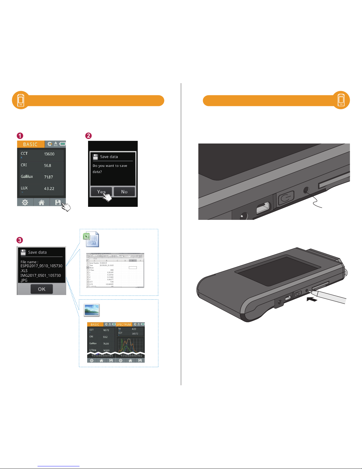
Press Save key on the lower right of the screen, and select “Yes” key.
The measurement data
are saved in the memory
card successfully.
Please record the file
name if necessary.
JPG file name:
IMGYYYY_MMDD_HHMMSS
.JPG
EXCEL file name:
ESPDYYYY_MMDD_HHMMSS
.xls
▲Can save the original data completely.
Fixed (Year) (Month) (Date) (Time)
Fixed (Year) (Month) (Date) (Time)
System Reset
Users can press the reset key to turn off the system
if system crashes.
Reset Key
to turn off the system.
※ Use a pen to press the reset key
2.2 Basic Measurement
Page 10

3
- 17- - 18 -
System Overview
3.1 Main Page
3.2 Measurement Modes Introduction
3.3 Measurement Introduction
3.4 Measurement Setting Introduction
3.5 Continuous Measurement Introduction
3.6 Customizing BASIC Mode List
3.7 Instruction of Spectrum Mode
3.8 FLICKER Mode Introduction
3.9 FREQUENCY Mode Introduction
3.10 ANALYSE Modes Introduction
3.11 CRI Mode Introduction
3.12 Switch Between CIE1931 & CIE1976
3.13 Compare Mode Introduction
3.14 BROWSER Mode Introduction
3.16 Connecting with Mobile APP
3.17 Connecting with uSpectrum
3.15 Transferring Data with PC Connection
Page 11
CIE
FREQUENCY
FLICKER
- 19 - - 20 -
3.1 3.1
Next
page
BASIC
ANALYSE
SPECTRUM
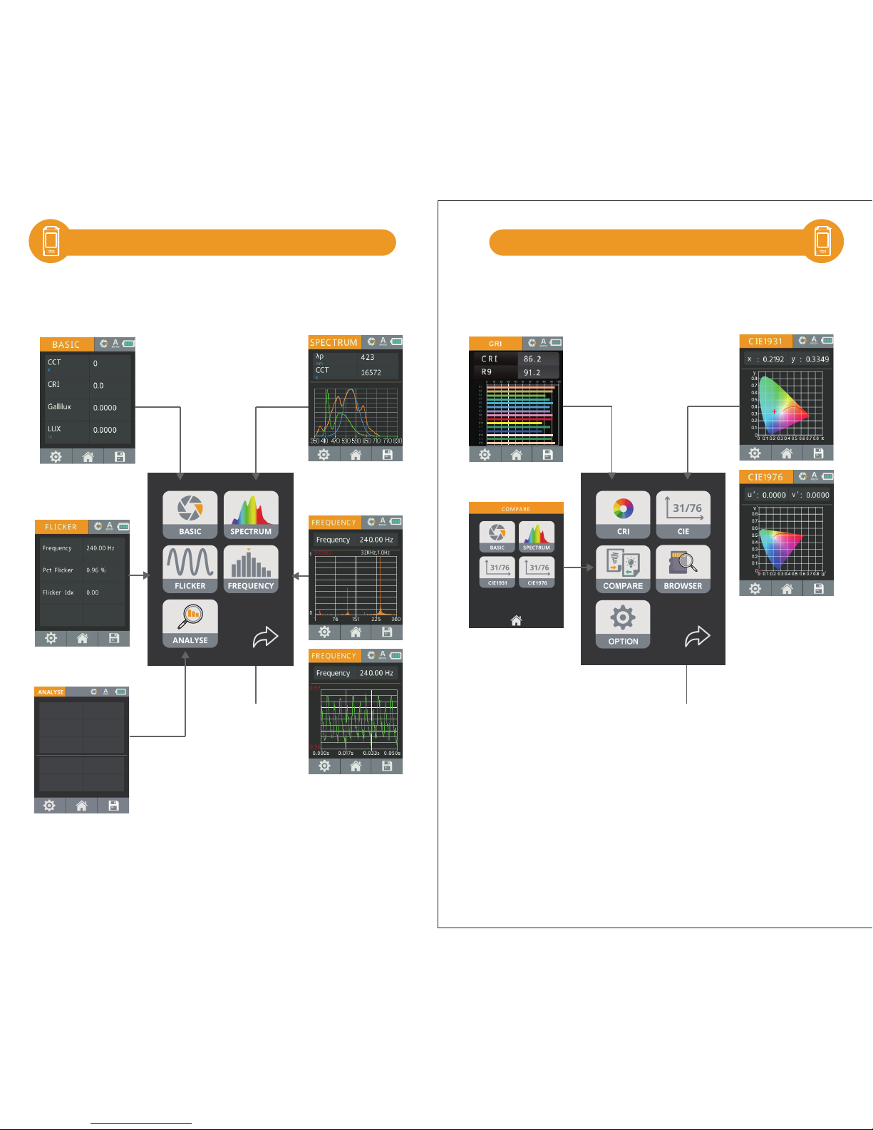
The interface of the product is touch screen operation. By touching the
screen with your figure, you may select the target menu or option.
The sub menus of each measurement mode are as shown below.
The interface of the product is touch screen operation. By touching the
screen with your figure, you may select the target menu or option.
The sub menus of each measurement mode are as shown below.
Back
page
COMPARE
CRI
Main Page Main Page
ID 0
LUX 0.0000 lx
Gallilux 0.0000
LUX Avg 00.00
Gallilux Avg 0.00
The analyse button allows you
to analyse the data of a defined
number of measurements.
Page 12
8
5 6 7
1 2 3 4
- 21 - - 22 -
3.2 3.3
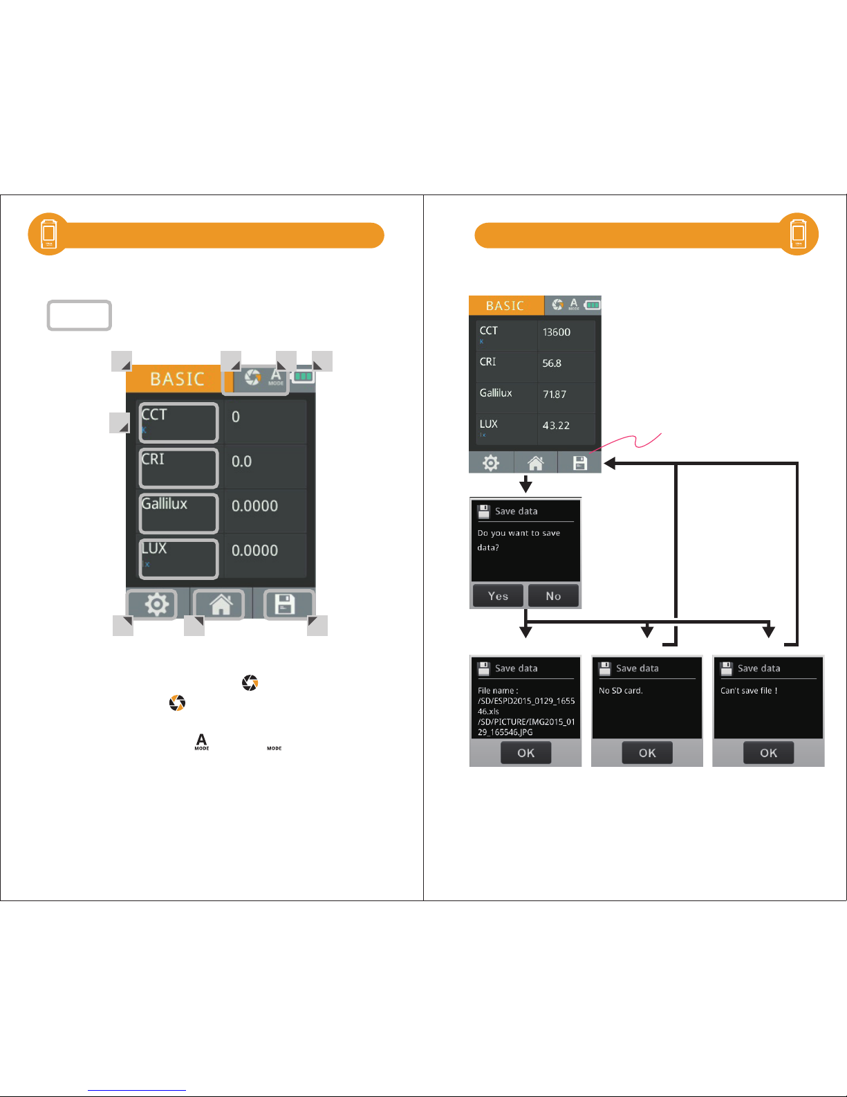
1. Measuring Mode - Basic
2. Measuring Function –Single operation
/continuous operation . For continuous measurement,
please refer to 3.5.
3. Exposure Mode -Automatic /Manual
4. Battery Power
5. Measurement Setting - please refer to 3.4.
6. Back to Main Page
7. Store the measured data- please refer to 3.3.
8. Show measured data – It shows different data based on the
measuring mode. You may make selections by yourself.
Save measured data:
Press save button
to save file
Confirm
Success Failed Failed
Please insert SD card
Please change SD card
Measurement IntroductionMeasurement Modes Introduction
Interface introduction:
Means button
M
Page 13
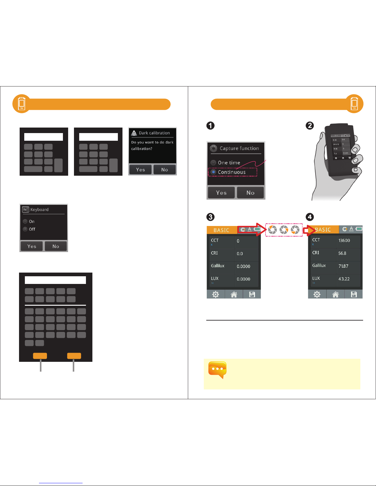
Keyboard
Long time exposure
Off
Normal
32K
1.0Hz
On
JPG
Sampling time
Dark calibration
Flicker resolution
Compare mode
Frequency domain (start)
1Hz
300Hz
Frequency domain (end)
0.000s
Time domain (start)
0.000s
Time domain (end)
- 23 - - 24 -
3.4 3.4Measurement Setting Introduction Measurement Setting Introduction
Previous
page
Back to
measurement page
Next
page
Measurement page
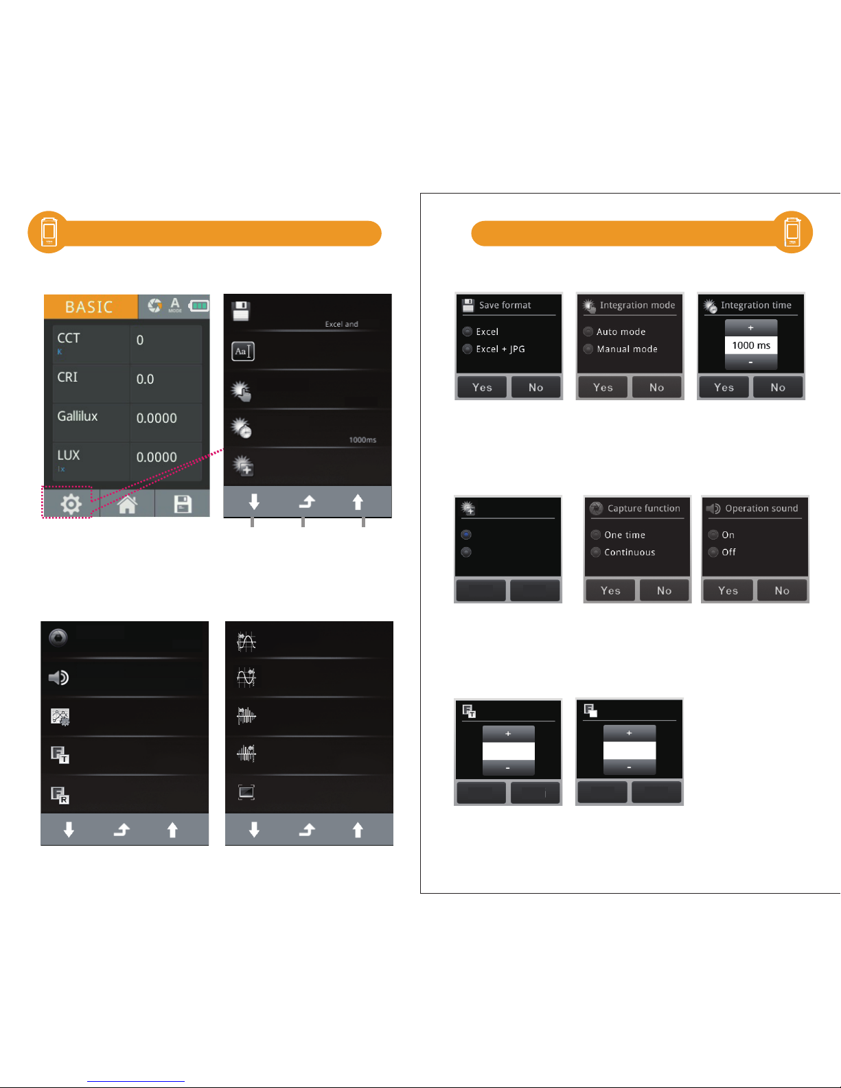
Please go to measurement page to do measurement settings.
+ / -:Adjust key
Yes / No:End of the setting
Capture Function Setting:
Operation Sound Setting:
Integration Time Setting:Integration Mode Setting:Save Format Setting:
Long time exposure Setting:
Sampling time Setting: Flicker resolution Setting:
Integration time
Integration mode
Save format
Auto mode
Off
Operation sound
One time
Capture function
4K
Sampling time
2.0Hz
Flicker resolution
R
Long time exposure
On
Off
Yes No
Yes No
Yes No
Page 14
0 1 2 3 4
5 6 7 8 9
A B C D E F
G H I J K L
M N O P Q R
S T
Y
DEL OK
Z
U V W X
OK
1 2 3
0 BS
4 5 6
7 8 9
OK
1 2 3
0 BS
4 5 6
7 8 9
- 25 - - 26 -
3.4 Measurement Setting Introduction 3.5
Keyboard Instruction:
Keypad ON: The keypad interface will show up when
saving file, which allows you to rename the file.
Keypad OFF: It will skip the keypad interface when saving files,
and name the file automatically.
Confirm the input value and save it,
then return to the interface.
Key in the number or
English letter.
Select it to show the
input value on the
upper side.
Delete the input English
letter or number.
Keyboard Setting:
Dark calibration Setting:Frequency domain(start) : Frequency domain(end) :
Continuous Measurement Introduction
Step1. Select the continuous capture
Step2. Press the capture key
Step3. Processing the continuous measurement
Step4. Press capture key again to stop continuous measurement
Basic mode
(start measurement)
press capture key
Basic mode
(after measurement)
Press the capture key again to
see the measurement results.
HATO ONE will process
measurement with
interval of 3 seconds.
※ The capture symbol
is rotating when HATO
ONE is processing
continuous
measurement.
Select Continuous
1. Continuous measurement has no beep sound after press capture key.
2. Users cannot save the measurement data while processing continuous
measurement.
3. Adjust the integration time is only allowed in the manual mode.
Page 15
5 6 7
1 2 3 4
Interface introduction:
Means button
- 27 - - 28 -
3.6 3.7 Instruction of Spectrum Mode
1. Measuring Mode - SPECTRUM
2. Measuring Function –Single operation
/continuous operation . For continuous measurement,
please refer to 3.5.
3. Exposure Mode -Automatic /Manual
4. Battery Power
5. Measurement Setting - please refer to 3.4.
6. Back to Main Page
7. Store the measured data- please refer to 3.3.
y
For more information about Measurement Index,
please refer to 5.2.
CRI CCT LUX
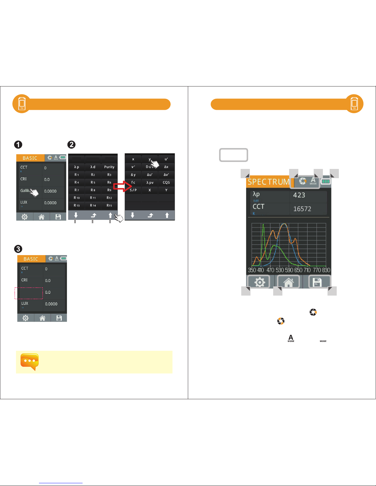
Customizing BASIC Mode List
Step1. Tap the box of measuring unit
Step2. Select an item from the list
Step3. The new data item will be displayed
Previous
page
Back to
BASIC mode
Next
page
The 4 items on the Basic list can be customized with different
units of measure (e.g. Gallilux fc, R9, LUX).
M
Page 16
- 29 - - 30 -
3.8 3.9
M
M
5 6 7
1 2 3 4
Interface introduction:
Means button
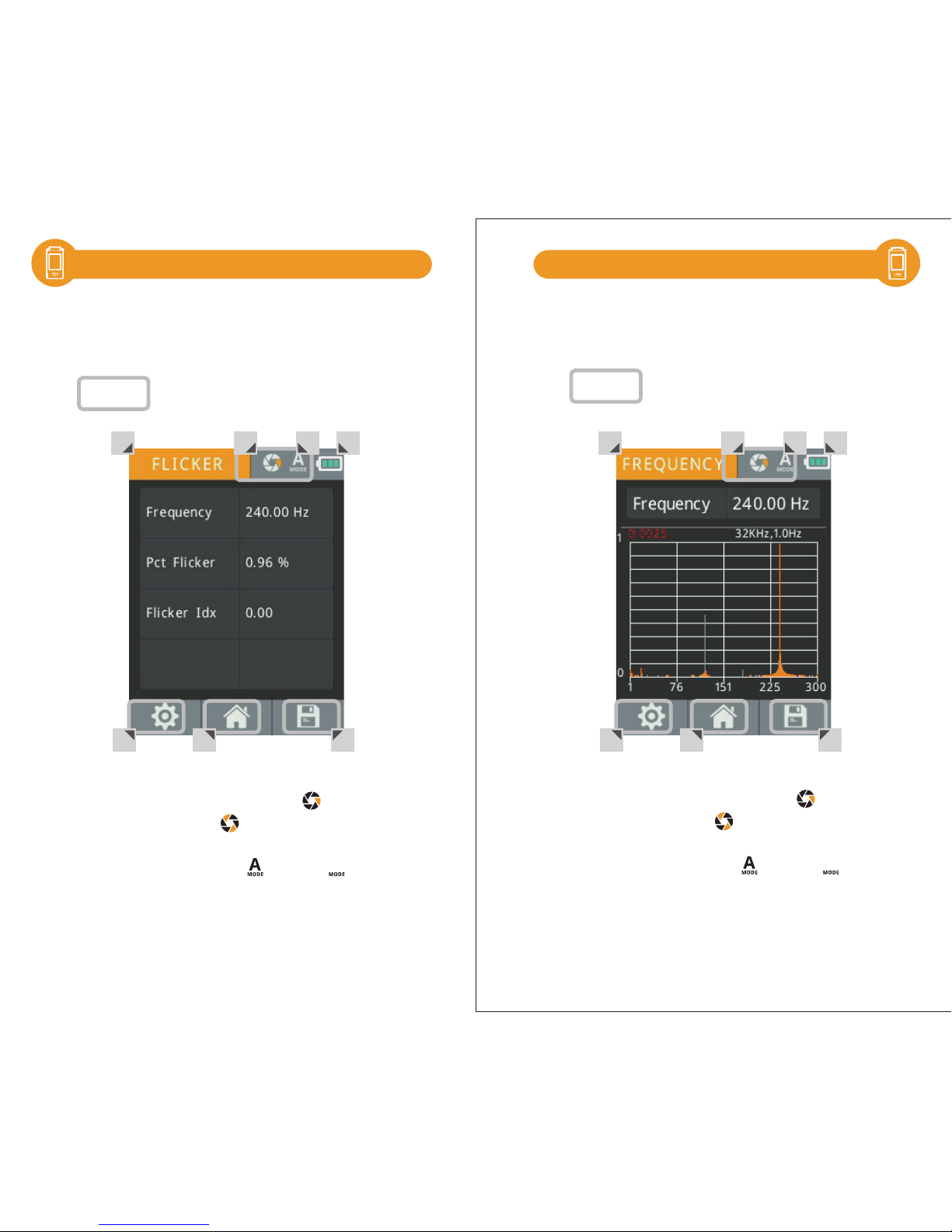
1. Measuring Mode - FLICKER
2. Measuring Function –Single operation
/continuous operation . For continuous measurement,
please refer to 3.5.
3. Exposure Mode -Automatic /Manual
4. Battery Power
5. Measurement Setting - please refer to 3.4.
6. Back to Main Page
7. Store the measured data- please refer to 3.3.
5 6 7
1 2 3 4
1. Measuring Mode - FREQUENCY
2. Measuring Function –Single operation
/continuous operation . For continuous measurement,
please refer to 3.5.
3. Exposure Mode -Automatic /Manual
4. Battery Power
5. Measurement Setting - please refer to 3.4.
6. Back to Main Page
7. Store the measured data- please refer to 3.3.
Interface introduction:
Means button
FLICKER Mode Introduction FREQUENCY Mode Introduction
Page 17
- 31 - - 32 -
3.9 3.10
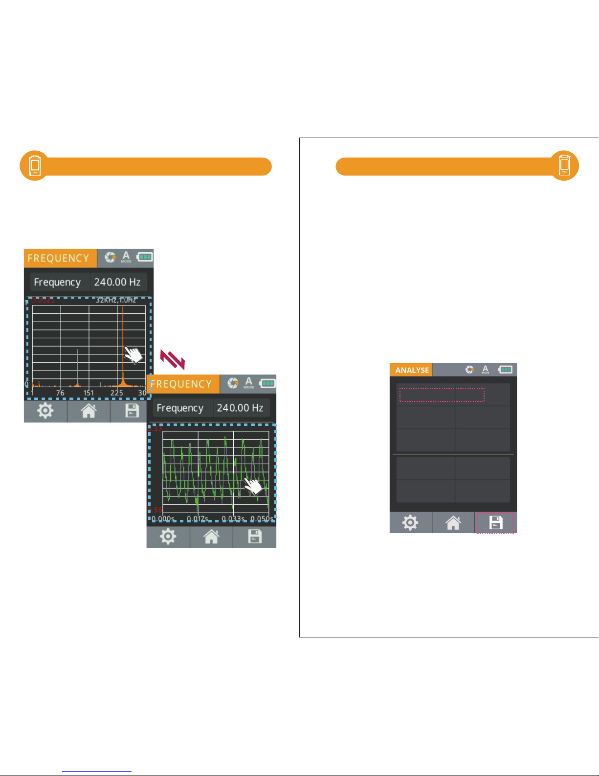
Touch the graph to switch the table between Frequency.
FREQUENCY Mode Introduction ANALYSE Mode Introduction
ID 0
LUX 0.0000 lx
Gallilux 0.0000
LUX Avg 00.00
Gallilux Avg 0.00
The analyse button allows you to measure and analyse data
of your whole barn trough multiple measurements.
Press ID to select the number of measurements.
Press ID to change to another measuring point.
Press Save icon to save the measurements,
When opening measured data on PC a report opens in
which the average, minimum and maximum values on:
LUX, Gallilux, Pct Flicker, Flicker index, Fc, CCT, CRI, CRI - R9
Additionally you will get Uniformity: Emin/Eav and Diversity:
Emin/Emax of lux, gallilux and Fc.
1
Page 18
- 33 - - 34 -
3.11 3.12
M
5 6 7
1 2 3 4
1. Measuring Mode - FREQUENCY
2. Measuring Function –Single operation
/continuous operation . For continuous measurement,
please refer to 3.5.
3. Exposure Mode -Automatic /Manual
4. Battery Power
5. Measurement Setting - please refer to 3.4.
6. Back to Main Page
7. Store the measured data- please refer to 3.3.
Interface introduction:
Means button
CRI Mode Introduction
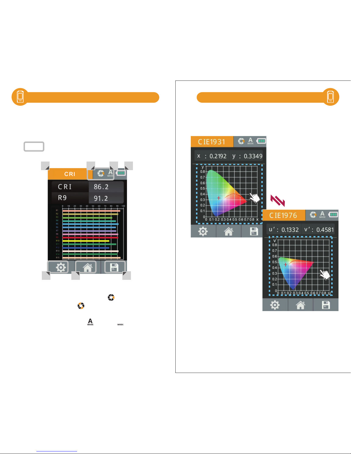
After entering the CRI Mode, user may see the
measured data such as CRI R1~R15 and Ra.
Switch Between CIE1931 & CIE1976
Touch the graph to switch the table between CIE1931
and CIE1976.
Page 19
3.13
- 36 -- 35 -
與手機APP連線
3.14
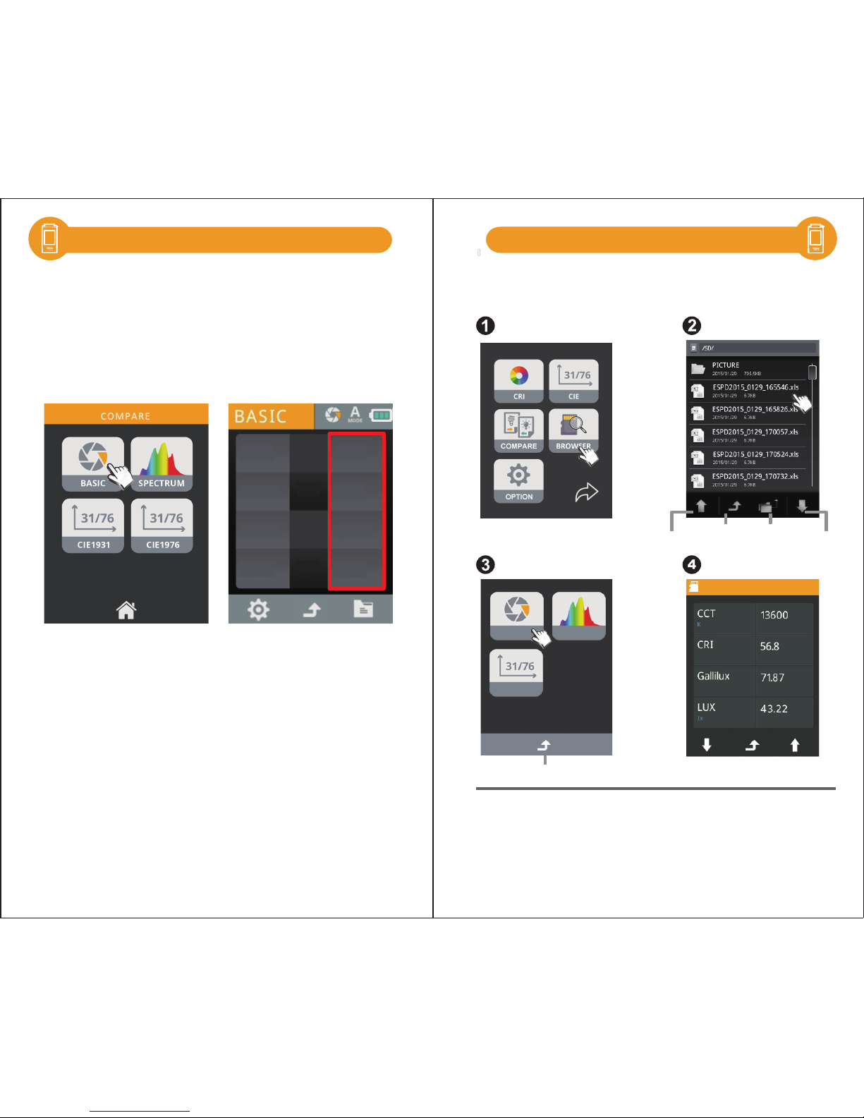
Users can use the real-time measurement or select
the historical measurement data to show the measured
light source data with parallel display. We offer four
modes that allow you to compare the measurement of
the source data: BASIC, SPECTRUM, CIE 1931 and CIE 1976.
After the measurement is
completed, the measured
light source data are
compared by parallel
display.
Select the "light source"
mode you need.
CCT
CRI
Gallilux
LUX
13600
56.8
71.87
43.22 lx
00532
0.0
0.0193
0.0022 lx
Compare Mode Introduction
BROWSER Mode Introduction
The Browser (on Home Screen) allows you to review historical
data that was previously saved to the SD card.
Step1. Press the “BROWSER”icon
Step2. A file browser will show the files on the SD card.
If you select an excel file, a review menu will be displayed.
Step3. Press any of the icons to review the data.
Step4. Displaying the data of excel file .
Previous
page
Back to
main manu
Return to the
previous folder
Next
page
Back to
file list
ESPD2018_0129_165546.xls
BASIC
CIE
SPECTRUM
Page 20
3.15
與手機APP連線
- 38 -- 37 -
WiFi Wing wireless remote control card
Measure
Install APP
Insert WiFi Wing card to the system. At IOS or Android platform, download
HATO ONE APP and install it on your mobile. Then you can connect
it with system for the measurement of wireless control.
※For more operation, please refer to Wing user manual.
Please visit UPRtek official site, http://www.uprtek.com
Download and install the HATO ONE APP on your Mobile.
Select WiFi HATO ONE
HATO ONE
WiFi Wing
wireless remote control card
( It is used to connect with APP.)
HATO ONE
WiFi connection
Transferring Data with PC Connection
Storage the measurement data:
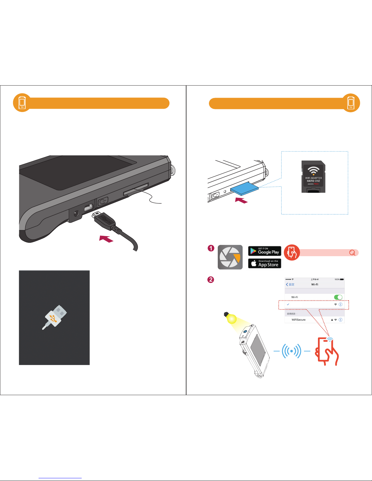
Inside the package has a USB cable, connect the mini USB to HATO ONE
and plug the USB to your PC then you can read the data saved in SD
card.
After connected USB cable, HATO ONE will display as below.
Insert SD card
3.16 Connecting with Mobile APP
Page 21
Set USB PC connection mode
Measure
Install uSpectrum PC software
uSpectrum
Install file
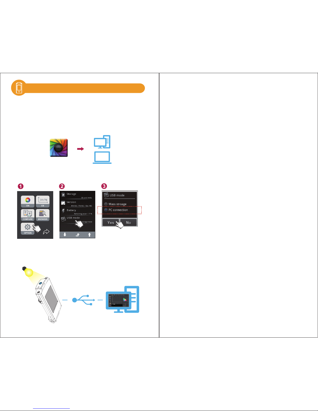
Please visit UPRtek official site, http://www.uprtek.com, Download
and install uSpectrum software on the PC. Then you can connect it
with the system for USB control of measurement.
Select “Option
”.
Select “USB mode”.
Select “PC connection
”
and press Yes.
USB connection
uSpectrum PC software
3.17
- 40 -- 39 -
Connecting with uSpectrum
Page 22
- 41 -
4
- 42 -
Specification
4.1 Product Specification
4.2 Product Appearance and Dimension
Page 23
- 43 - - 44 -
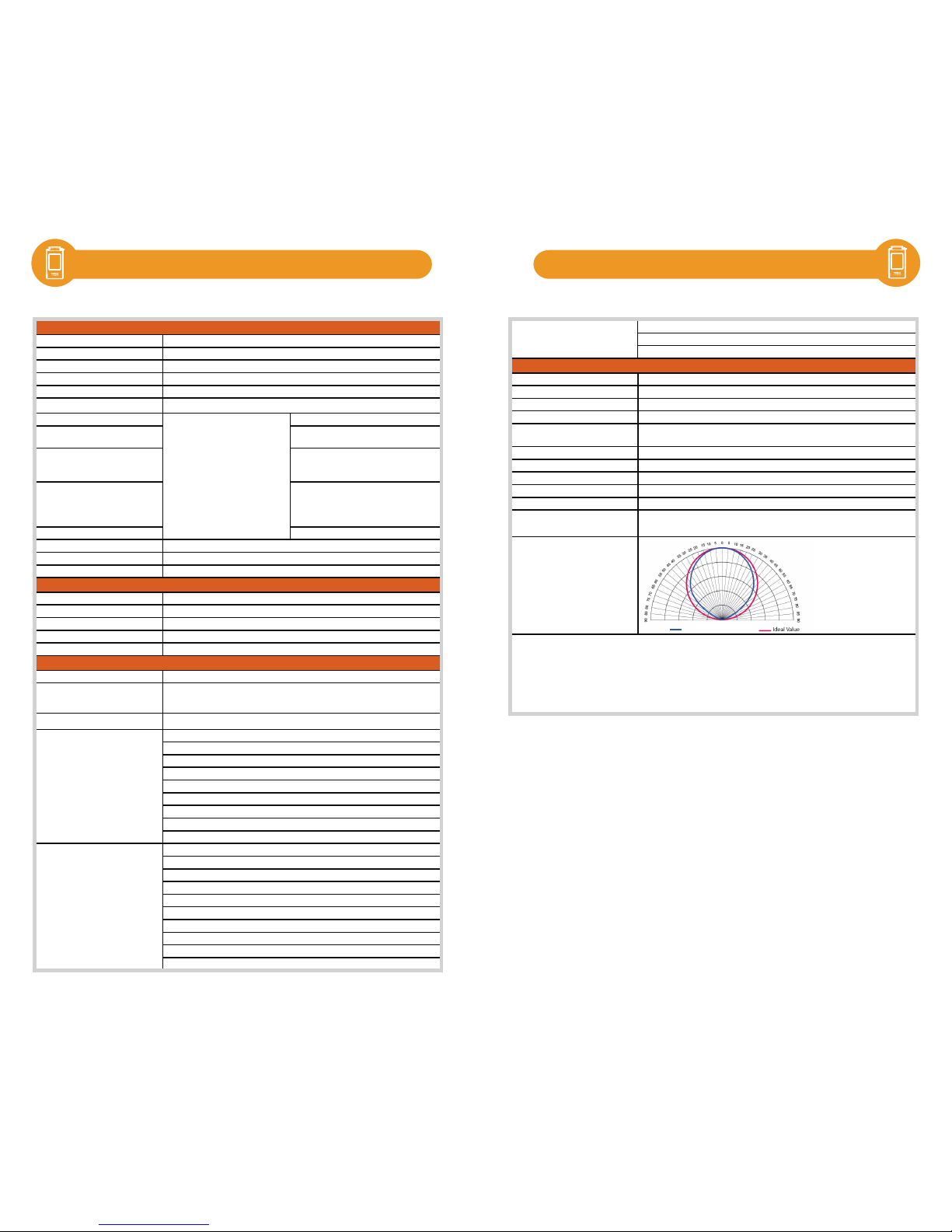
4.1 4.1 Product Specification Product Specification
Sensor
Wavelength Range
Wavelength Data Increment
Spectral Bandwidth
Wavelength Reproducibility
Measurement Range
Illuminance Accuracy ± 2.5%
Illuminance Repeatability (2σ)
0.2% (100 ~ 100,000 lx)
0.5% (5 ~ 100 lx)
Color Accuracy
± 0.002 in CIE 1931 x,y (100 to
100,000 lx)
± 0.0025 in CIE 1931 x,y (5 to 100 lx)
Color Repeatability (2σ)
0.0002 in CIE 1931 x,y (500 to 100,000
lx)
0.0004 in CIE 1931 x,y (30 to 500 lx)
0.001 in CIE 1931 x,y (5 to 30 lx)
CCT Accuracy ± 2%
Stray Light
Integration Time Range
Digital Resolution
Measurement Range
Sampling Rate
Frequency Range
Frequency Resolution
Flicker Accuracy
Capture Function
Operation Mode
Integration Mode
9. Analyze Mode
Measuring Modes
8. Compare Mode
2. Gallilux
(1) CIE 1931 XYZ Value
Measuring Capabilities
1. Illuminance (LUX)/Foot Candle (fc)
3. Correlated Color Temperature (CCT)
4. CIE Chromaticity Coordinates
8. Percent Flicker
9. Flicker Index
7. Flicker Frequency
6. Color Rendering Index (CRI, Ra)/R1 to R15
5. Dominant Wavelength (λd)
5. Frequency Mode
6. Browser Mode
7. Option Mode
4. Flicker Mode
Auto/Manual
1. Basic Mode
2. Spectrum Mode
3. CIE 1931/1976 Chromaticity Mode
Feature
One time/Continuous
Standalone Mode/WiFi Mode
*4
/USB Mode (MSC Mode*5 + PC
connection)
5 to 50k Hz
2, 4, 8, 16, 32 Hz
± 5%
5 to 100,000 lx
100k sample/sec
-25 dB max.
*3
100 us to 1,000 ms
16 bits
Illuminant A @ 2,856 K
*2
350 to 780 nm
1 nm
Approximately 12 nm (Half Bandwidth)
Flicker
Spectrum
CMOS Linear Image Sensor
± 1 nm
*1
5 to 100,000 lx
Display
Max. Files
Battery Operation Time
Power
Data Output Interface
Data Format
Dimensions
Weight (with Battery)
Operating
Storage Temperature/Humidity
Display languages
Cosine Correction
*1:Input source must be a stable light source.
*2 :Temperature 23±2℃ and relative humidity 50% or less.
*3:Input the 550nm monochromatic light and measure the stray light ratio at 550nm ± 40nm.
*4:It can be connected to mobile phones and tablets.
*5:MSC Mode- Mass Storage Class.
The company reserves the right to change product specifications at any time without prior notice.
-10 to 40 ℃, relative humidity 70% or less without condensation
E
nglish/Traditional Chinese/Simplified
C
hinese/Japanese/Spanish/German/French/Italian/Russian
1
47.5 x 78 x 24 mm (H x W x D)
225 g ± 10 g
0 to 35 ℃, relative humidity 70% or less without condensation
A
dapter; 2500 mAh (3.7V Rechargeable Li-ion Battery)
SD Card (SD2.0,SDHC/up to 32G)/Mini USB Port (USB 2.0)/WiFi SD Card
compatible with iOS and Android
Compatible Excel/JPG
3.5" 320X240 Resistive Touch LCD
≒ 68,000 Files @ 8GB SD Card (Excel + JPG)
≦ 5 hours / Fully Charged
1
2. Scotopic and Photopic Ratio (S/P)
System Configurations
10. Peak Wavelength (λp)
11. Peak Wavelength Value (λpV)
Measuring Capabilities
HATO ONE spectro- gallilux meter
Page 24
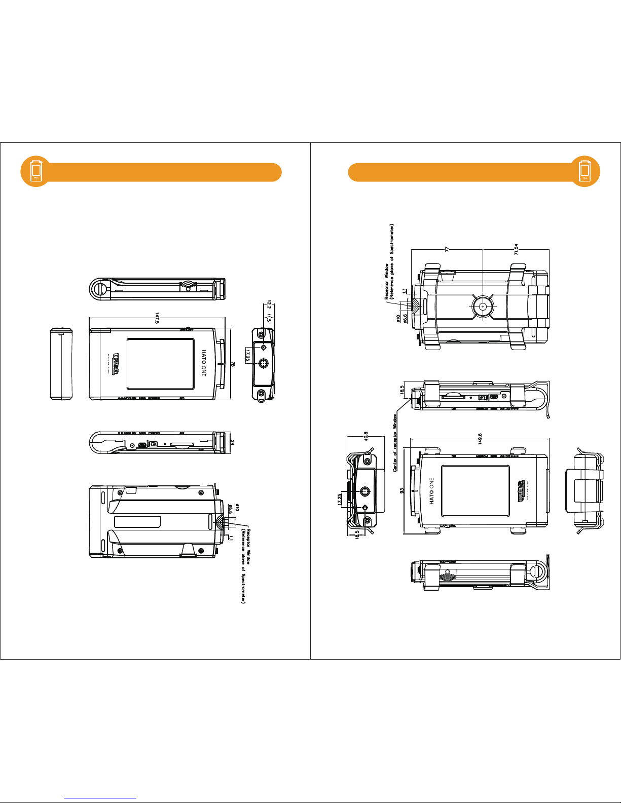
- 45 - - 46 -
4.2 4.2
Unit: mm Unit: mm
Product Appearance and Dimension Product Appearance and Dimension
Back Support Installation Diagram
Page 25

5
- 47 - - 48 -
Appendices
5.1 Product Warranty Terms
5.2 Measurement Indexes
5.3 Q&A
Page 26
- 49 - - 50 -
5.1 Product Warranty Terms 5.1 Product Warranty Terms
■
■
■
■
■
■
UPRTEK provides the service of repairing or changing
equivalent products for the customer in case of the material
or functional defect and fault during the product warranty
period.
If the consumer finds any functional defect or fault or finds
any part missing within 7 days after purchasing the
product, it should consult the original seller and report to
the vendor immediately. Moreover, it should leave the
contact information, so the customer service personnel of
the original vendor will check it out and generate the
number of changing new product for the customer. In this
case, the original vendor provides the service of “changing
new product” within 7 days.
The customer should return the product to the original
vendor within 30 days after getting the repair number. As
for the international customer, it permits the flexibility of
logistical time and expands the time for returning the
product to the original vendor.
If it exceeds the period for changing new product (seven
days), the functional non-compliance or defect found on
the product should go through RMA workflow. When any
product needs to be returned to the original vendor for
repair, it should consult the business service personnel
via Email, fax or phone call to apply for repair number
before returning the product to the original vendor for
repair service.
After the original vendor receives the returned product, the
internal engineer of the Company will check it initially and
confirms the causes for product defect. If it is within the
warranty period and it is the functional fault of the product,
it should follow the general repair workflow. However, if
the engineer checks it is human damage rather than
functional fault, it is inapplicable to the warranty term.
Remarks: It requires complete package when returning the
product to the original vendor. There should be no part
missing or scratch on the surface unless the part is found
missing when the product is delivered. Under this circumstance, the original vendor reserves the ultimate right to
determine whether to change new product.
Remarks: To avoid damage during the product transportation, we strongly recommend choosing international express
service and protecting the product carefully.
The warranty term is inapplicable to the damage caused by
unnatural or external factors, such as the following
circumstances:
1.When the fault is caused by the natural disaster and
improper human operation rather than the product itself;
2.When the product is repaired or disassembled by others
rather than the technician authorized by the company;
3.When the warranty volume label or disassembly-proof
volume label is modified, damaged or gone;
4.When the product serial number is wrong, damaged or
unclear.
UPRTEK is not liable to the product defect or damage
caused by any factor during the transportation of sending
HATO ONE series product for repair. It is recommended
taking out the storage device, packing and transporting the
product properly on your own before sending the product for
repair.
UPRTEK is not liable to the compensation for the operation
loss, expected cost loss, data loss caused by or related to
the usage of the product of the Company, as well as any
other indirect, accident or derivative loss or damage
provided it is permitted by the laws.
Warranty Principles
Limited Warranty
Exemption from Liabilities
1.Changing new product:
2. Repair service:
Page 27

- 51 - - 52 -
5.1 5.1
■
■
■
UPRTEK’s warranty service terms are only applicable to the
consumers who purchase the company products through
formal or legal sales channels.
If any damage or fault occurs to HATO ONE series product
after two years of warranty period, the consumer may still
return the product to UPRTEK for repair. However, the
repair service should be charged based on the product fault
or damage condition. If the engineer finds the following
situations, it is suggested purchasing new product:
Consumer may send the product back to the original vendor
RMA repair service through either of the following two
methods:
UPRTEK doesn’t produce or manufacture all materials and
parts of the product. If the target material and part is
discontinued within the warranty period, UPRTEK is entitled
to replace it with equivalent alternative to finish repair.
1.Host of HATO ONE series product:
UPRTEK provides two years of warranty service for all HATO ONE
series products, with free calibration service for one time.
2.Product supplies and related accessories:
The product suppliers and the related accessories such as
battery, tripod and neck strap, are excluded from the warranty
service.
The qualifies agent or distributor may receive or deliver the
host of HATO ONE series product for basic inspection, so as
to confirm whether the device needs to be returned to the
original vendor for further calibration service.
■
The HATO ONE series product or part is not available
anymore;
■
The functions of the device can’t be recovered due to the
damage caused by water, strong collision, serious
contamination or corrosion.
■
The product is deformed due to falling or strong collision,
and the functions can’t be recovered even if the main
parts are replaced.
■
The product is aging or used in adverse environment, so
many parts don’t work normally. In this case, it has to be
changed.
■
The part is not available even if it is it the warranty period.
URL of qualified agents or distributors: www.uprtek.com.
■
■
The consumer sends the product to UPRTEK’s agent or
distributor which will return it to the original vendor for repair.
The consumer sends the product to UPRTEK for repair
directly.
The basic inspection service provided for the consumer is
charged based on the announcement made by UPRTEK.
Applicable Subjects for Warranty Terms Service after Warranty Period
Warranty Period
Other Notes
Sending for Repair
Services Provided by Authorized Agent or Distributor
Product Warranty Terms Product Warranty Terms
Page 28
- 53 - - 54 -
5.2 Measurement Indexes 5.2 Measurement Indexes
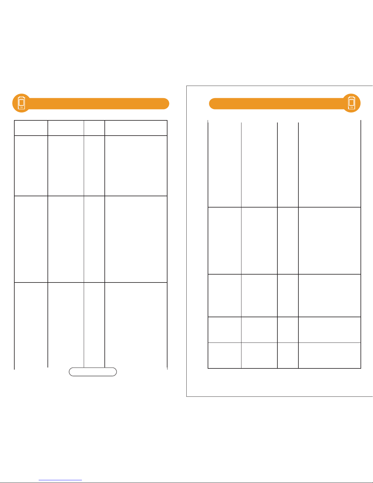
Abbreviation Full Name Unit Description
CCT Corelated
Color
Temperature
K
(kelvin)
LUX Illuminance lx
λp
(LambdaP)
Peak
wavelength
nm
λpV
(LambdaPV)
Peak
wavelength
value
mW/m
2
CRI (Ra) Color
Rendering
Index
---
------
R1、R2
….R15
Rendering
Index
---
next page
The color temperature is
the color radiated by a
black-body radiator
under different
temperatures. CCI has
the color that is the
closest to the ideal
black-body radiator.
The measure of light
intensity. The
corresponding unit for
lux in English and
American units is the
foot-candle. One
foot-candle is
approximately 10.764
lux.
Gallilux
The measure of light
intensity as perceived
by poultry.
It is the wavelength with
the highest power in the
measured spectrum.
It is the highest power in
the measured spectrum,
in the unit: mW/m2.
As defined by CIE, R1~R8
represent the value of
eight standard colors,
while CRI(Ra) is the
average value of R1~ R8.
The value 100 indicates
the best quality of light
source, while the value 0
indicates the worst
quality of light source.
It represents the quality
of light source, with the
indexes corresponding
to 15 standard colors,
including: R1: light
grey-red; R2: dark
grey-yellow; R3:
saturated yellow-green;
R4: middle
yellow-green; R5: light
yellow-green; R6: light
blue; R7: light
purple-blue; R8: light
red-purple; R9: saturated
red; R10: saturated
yellow; R11: saturated
yellow; R12: saturated
yello; R13: white skin
color; R14: Leaf green;
and R15: yellow skin
color.
Page 29
- 55 - - 56 -
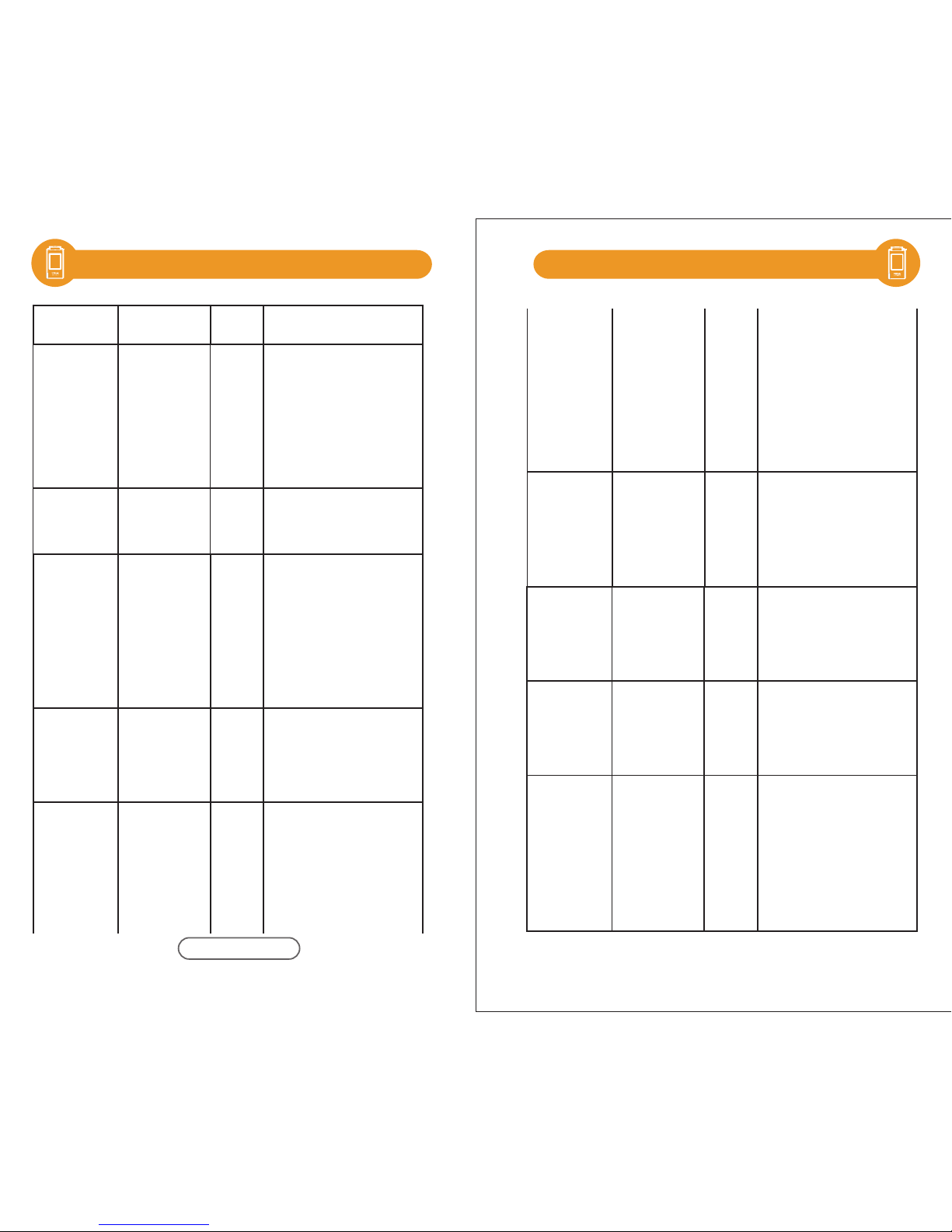
5.2 Measurement Indexes 5.2 Measurement Indexes
I-Time Integration
time
ms
λd
(LambdaD)
Dominant
wavelength
nm
The integration time
measured by the
spectrometer.
The dominant wavelength
is used to express the color
of the measured light. It
could be hybrided by the
spectrum color of the
wavelength and the
standard illuminant E(x,y =
0.333, 0.333).
Abbreviation Full Name Unit Description
x
y
X
Y
Z
CIE1931
color
coordinate
---
u'
v'
CIE1976
color
coordinate
---
Δx
(deltax)
(dx)
CIE1931 x
color
coordinate
difference
---
Δy
(deltay)
(dy)
CIE1931 y
color
coordinate
difference
---
Δu'
(deltau)
(du)
CIE1976 u'
color
coordinate
difference
---
Δv'
(deltav)
(dv)
CIE1976 v'
color
coordinate
difference
---
Duv
(Δuv)
CIE1960 uv
color
coordinate
difference
---
The color coordinate was
built by CIE in 1931.
The color coordinate was
built by CIE in 1976.
It is the uv distance between
CIE1960 coordinate and the
Planck’s blackbody
radiation with the same color
temperature. The value close
to 0 indicates the color
temperature and color are
It is the x difference
between CIE1931
coordinate and the
Planck’s blackbody
radiation with the same
color temperature.
It is the y difference between
CIE1931 coordinate and the
Planck’s blackbody radiation
with the same color
temperature.
It is the u' difference
between CIE1976 coordinate
and the Planck’s blackbody
radiation with the same
color temperature.
It is the v' difference between
CIE1976 coordinate and the
Planck’s blackbody radiation
with the same color
temperature.
closer to that of the
blackbody radiation. The
positive value indicates it is
above the blackbody
radiation, while the
negative value indicates it
is below the blackbody
radiation.
next page
Page 30
- 57 - - 58 -
5.2 5.2
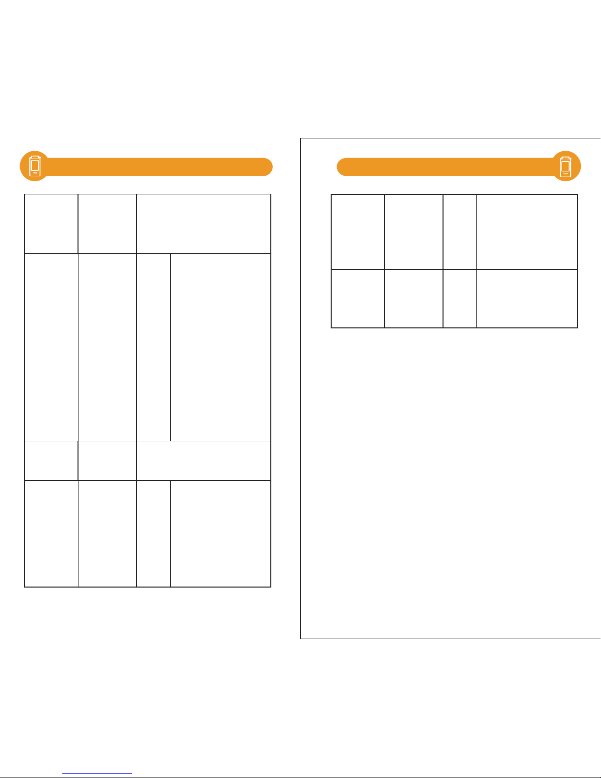
S/P
(SP-ratio)
Scotopic
vision/
photopic
vision ratio
---
W/m
2
W/m
2
Irradiance
The sensitivity of human eyes
varies with the light of
different wavelength. It can
get the data such as
illuminance based on the
brightness function. However,
the brightness function is
different for human eyes
under high brightness and
low brightness. Therefore, it
defines the ratio of photopic
vision under high brightness
and scotopic vision under low
brightness, which is called S/P
ratio.
It is the irradiance within the
range of the wavelength
specified in the specification.
Findex
(Flicker Idx)
Fpercent
(Flicker Pct)
%
Hz
Flicker index
---
Flicker
percent
Flicker
Frequency
Freq
(Frequency)
Flicker index= Area above the
mean value /area below the
mean value. Higher value
represents obvious flicker.
Flicker percent=(Maximum
value-minimum value)/
( Maximum value + minimum
value). Higher value
represents obvious flicker.
It is the flicker rate of the
measured light, or the
frequency shown per second.
fc fcFootcandle
2
It is based on the unit of
lm/ft .
Measurement Indexes Measurement Indexes
Page 31
- 59 - - 60 -
5.3
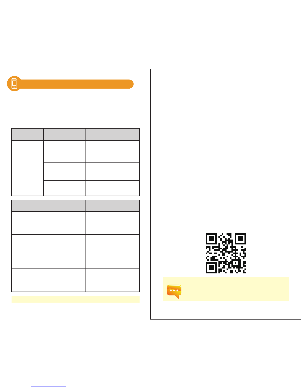
To get more information related to operation, firmware upgrade
and warranty terms; online application for correction and Repair
service, please contact [email protected]
Q&A
State Inspection item Solution
Check whether the
battery is installed
correctly.
Check whether the
battery runs out of power.
Check whether the
battery connector is dirty.
Power-on failure
(No display)
Why I feel the card is stuck when inserting
and unplugging it?
What is the function of dark calibration?
Do I need to perform dark calibration at
every startup.
Why my SD card can’t be used on
HATO ONE?
The following situations are not fault. Please double check it before
requesting for repair. If it doesn’t work normally after the inspection,
it could be caused by fault of the device. In this case, please take out
the battery and contact the seller or the vendor for repair.
Other questions? Visit the FAQ page at our website: www.hato.one
Item
Please don’t install the battery
inversely, or push it in violently,
which may destroy the battery
spring.
Please charge the battery for 6
hours for the first use. (Please refer
to 2.1)
Please wipe it with dry cloth.
It is the anti-shedding function
designed specially. It prevents SD card
shedding in case of collision under
external force, which may cause
write-in error.
The SD card should be formatted into
FAT before being inserted into HATO
ONE. Moreover, the memory of SD
card is required to be 1G or higher.
The dark calibration is also known as zero
calibration. As the temperature change of
the environment affects the measurement
results, the user is suggested performing
dark calibration before measurement, so as
to improve the measurement accuracy.
(As for the calibration instruction, please
refer to 2.6).
Solution
 Loading...