

Page 1

HATO 400Y HEL 11C
SLIDING GATE OPERATOR
USER’S MANUAL
Page 2

2
OUTLINE
1. Important safety information………………………3
2. Main technical parameters ………………………3
3. Installation …………………………………………3
4. Connecting …………………………………………7
5. Control ……………………………………………10
6. Check ……………………………………………14
7. Maintenance………………………………………14
8.Troubleshooting …………………………………15
Page 3

3
1.Important safety information
Carefully read and follow all safety precaution and warnings before attempting to install and use this operator, incorrect
installation can lead to severe injury.
The gate operator should be installed by a qualified technician; otherwise, serious personal injury or property
damage may occur.
The auto-reverse function must be checked during installation to ensure that the gate can auto-reverse in the
event of obstruction.
This auto-reverse function should be regularly inspected and adjusted, if necessary.
When opening or closing the gate, do not attempt to walk or drive through the gate.
Children should not be allowed to play near or operate automatic gates.
The automatic gate operator must be grounded.
Install the gate operator on the inside of the property, DO NOT install it on the outside of the property where the
public has access to it.
Be careful when in close proximity to moving parts where hands or fingers could be pinched.
Do not allow control devices to be placed so that a person can access them by reaching through the gate.
In the event of power failure, an emergency release key allows you to operate the gate manually.
The operator should be switched off before repairing it or opening its cover.
Please erase and reprogram the code after installing the operator.
2. Main technical parameters
3. Installation
The HATO 400 Y rack-driven gate operator operates by forcing a drive rack past a drive gear. The entire configuration
is shown in Fig.1. The gate operator must be installed on the inside of the gate.
Gate preparation
Be sure the gate is properly installed and slides smoothly before installing the DKC400Y sliding gate operator. The
gate must be plumb, level, and move freely.
Conduit
In order to protect the wires, use PVC conduit for wires, conduit must be set into the concrete when it is poured. Wires
within the conduit shall be located or protected so that no damage can result from contact with any rough or sharp
part.
Type
HATO 400Y
Power supply
AC 220V, 50Hz
Motor speed
1400 r/min
Gate moving speed
11m/min (19 teeth)
Output torque
14N·m
Limit switch
Spring limit switch
Noise
≤62dB;
Environmental temperature
-20ºC~+50ºC
Page 4

4
Fig.1
Concrete pad
The base unit of the gate operator requires a concrete pad in order to maintain proper stability. The concrete pad
should be approximately 300mm x 200mm x 200mm deep in order to provide for adequate operation.
Anchors
You can use the anchors, bolts, washers and nuts that are provided with the operator. These anchors must be set into
the concrete when it is poured, or you can use wedge anchors.
Operator
In locations where ground freeze is possible, mount the gate operator on installation pad as shown in Fig.2. Check the
operator and make sure it is lined up with the gate.
Conduit
Installation pad
Gate operator
Gear
Nut
Spring washer
Plain washer
Anchor
Bolt
Nut
Spring limit switch
Wires
Fig.2
Installation of rack (see Fig.3)
﹡ If you have installed an external
button switch, you must use two
conduits: one for main power wire,
another one for low voltage wire
(button switch).
Page 5
5
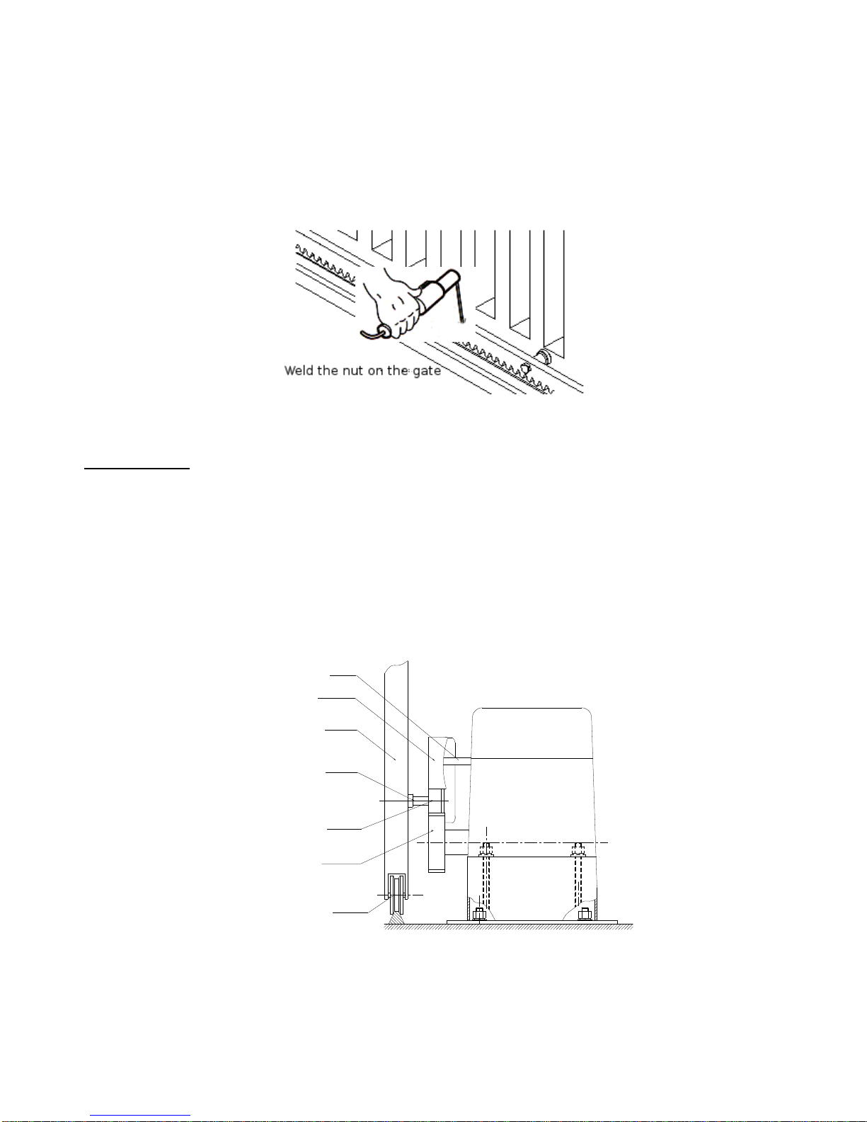
Fix the three nuts (in the same package with rack) on the rack element.
Lay the first piece of rack on the gear and weld the first nut on the gate.
Move the gate manually, checking if the rack is resting on the gear, and weld the second and third nut.
Bring another rack element near to the previous one. Move the gate manually and weld the three nuts as the first
rack, thus proceeding until the gate is fully covered.
When the rack has been installed, to ensure it meshes correctly with the gear.
The space between rack and gear is about 1mm.
Fig.3
Spring limit switch
To ensure safety, it is recommended to install plastic blocks at both ends of the gate to prevent the gate from
sliding out of the rail. The rail must be installed horizontally.
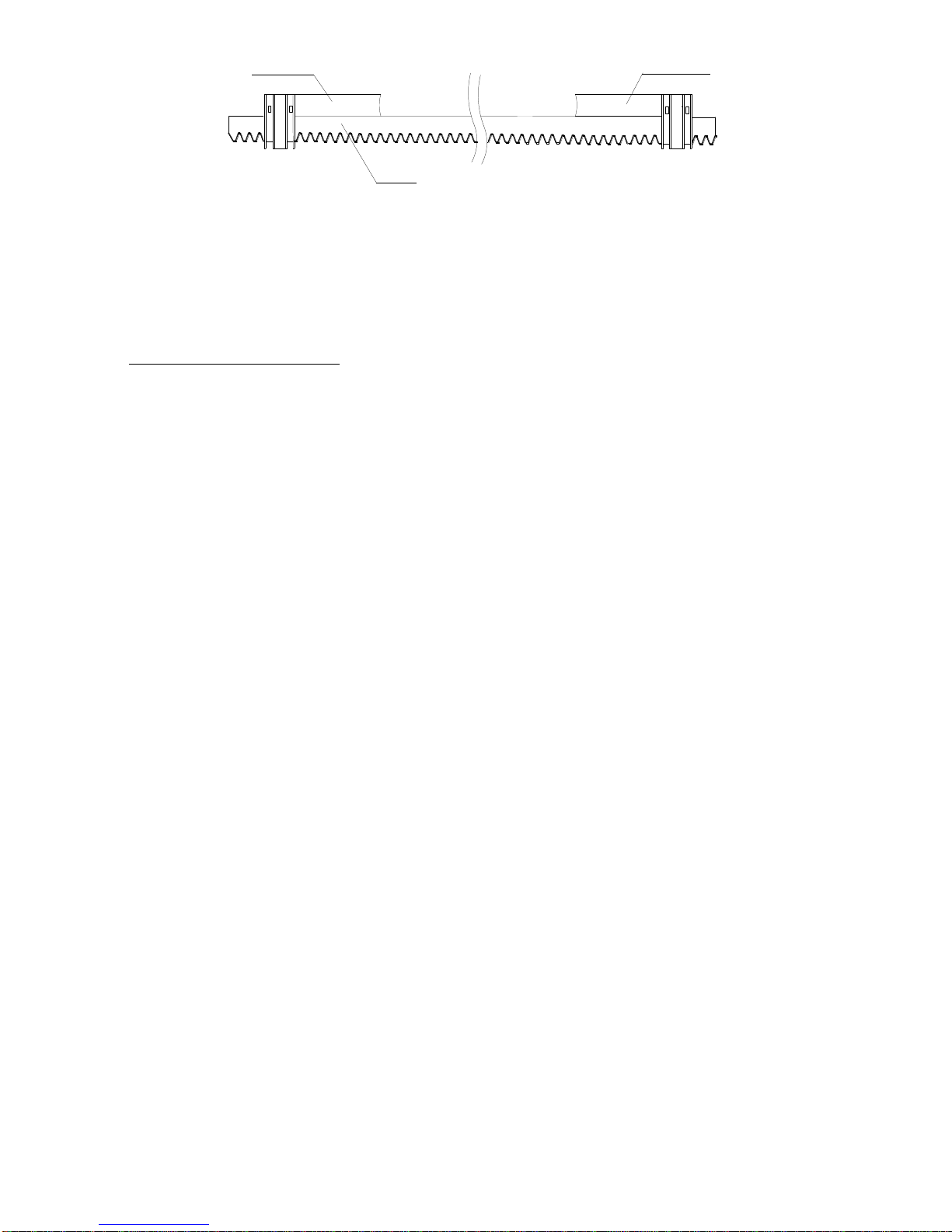
Install the plastic block as shown in Fig.4 and Fig.5. The spring limit switch and blocks are used to control the
position of the gate.
Release the gear clutch with the key and push the sliding gate manually to pre-determine the position, fix the
block to the rack and then tighten the gear clutch with the key. Moving the gate electrically, adjust the block to the
proper position until the position of the opening and closing meet the requirement.
Block
Gate
Rack
Gear
Guide rail
Spring limit switch
Nut
Fig.4
Page 6
6
Rack
Left block
Right block
Fig.5
CONFORMITY DECLARATION:
Motor Hato 400Y meets the requirements set out in the following provisions:
It’s in accordance with Machine Directive 2006/42/WE and following modify.
It’s in accordance with the following directive CE:
Electromagnetic compatibility Directive EMC 2014/30/UE and following modify.
Low tension Directive LDV 2014/35/UE and following modify.
Have been applied the following harmonized norms:
EN60335-1:2012, EN60335-2-103:2015-3, EN 55014-1:2012, EN 55014-2:2015-06,
EN 61000-3-2-2014-10, EN 61000-3-3:2013-10
Page 7
7
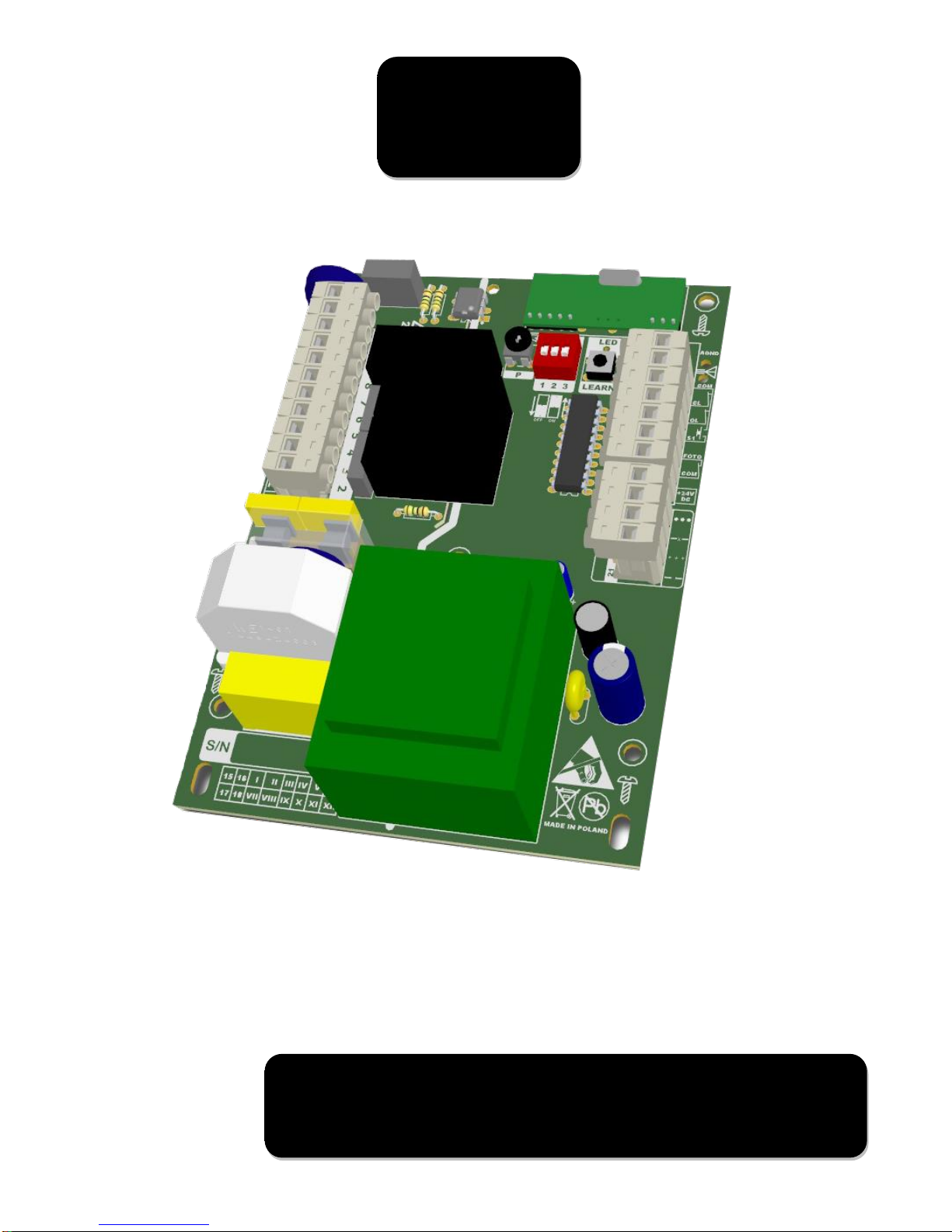
Controller of Gate
Drives for 230Vac
500W Motors
USER’S MANUAL
Page 8
8
SOFTWARE
MARKING
NOTES
1.2.0-C-NO
11:8.2.2/6.1.0
HEL11C
Before the installation and first use of the controller read the manual carefully and keep it for future reference.
According to the Machinery Directive 2006/42/CE, the product must not be put into service until the final
machinery into which it is to be incorporated or of which it is to be a subassembly has been declared in
conformity with the provisions of directives and relevant regulations which the final machinery must
comply with.
Safety recommendations and precautions:
Before installing and using the drive read all safety warnings and rules. Incorrect installation and failure to
observe the standards included in the manual can cause serious accidents.
• The controller can be installed only by qualified personnel with relevant licences.
• A basic protection against electrostatic discharges (ESD) shall be provided during the installation.
• Caution shall be exercised during the installation. The controller uses the 230Vac voltage (hazardous to
health and life).
• All works related to the correct functioning of the device (connection, start-up, operation) must be performed
in accordance with relevant regulations concerning the use of electrical machines and in line with the OHS
regulations.
• Do not connect the supply voltage earlier than specified in this manual! Failure to comply with this
recommendation can cause an electric shock.
• Check the gate condition before starting the installation: the gate should not swing too much, it should move
easily and smoothly.
• Before the installation, remove unnecessary ropes and secure the equipment, e.g. locks.
• Children, disabled persons and mechanical vehicles should not be present in the vicinity of the gate during
the installation.
• All fixed controls should be located near the gate, but away from the moving parts and out of reach of
outsiders.
• Disconnect the power supply before repairing or removing any part of the gate.
• Children and mentally disabled persons must not operate the gate by themselves.
• Motor and applicable force can be done by qualified personnel equipped with gauge force meter.
• In the controller without encoder input it is necessary to connect gate optical curtain or other safety elements
preventing from accidentally crush.
• Fluorescent lamps cannot be connected to the controller.
The controller can be used only in specified applications.
Failure to observe these instructions can lead to serious injuries or destruction of the equipment. The
manufacturer will not be liable for losses and disruption in work resulting from non-observance of this installation
and operation manual.
According to relevant regulations concerning the disposal of used equipment by the private
users in the European Union, an object bearing this symbol MUST NOT be disposed of
together with regular wastes. In such case the user is responsible for correct disposal by
delivering the equipment to a specialized outlet or to the manufacturer who will take care of
the further disposal. Separate collection and recycling of used equipment facilitates the
environmental protection and ensures that disposal is carried out in a manner safe to human
life and the environment. This remark also applies to spent batteries, disposable and
rechargeable.
Page 9

9
Version : HEL11C
• – cooperates with Hato’s transmitters operating at a 433.92 MHz frequency and compatible with
Keeloq protocol.
• – with encoder input
• – lamp control by relay
Table of contents:
OUTLINE ........................................................................................................................................................................................... 2
Anchors ............................................................................................................................................................................................. 4
1. Application and functionality of HEL11C. ......................................................................................................................... 10
2. Installation .................................................................................................................................................................................. 10
2.1 Limit switches connection .................................................................................................................................... 10
2.3 Photocell connection ........................................................................................................................................... 10
2.4 Step-By-Step pushbutton connection .................................................................................................................. 11
2.5 Capacitor connection ........................................................................................................................................... 11
2.6 Motor connection ................................................................................................................................................ 11
2.7 Signalling lamp connection .................................................................................................................................. 11
2.8 Mains supply connection ..................................................................................................................................... 11
2.9 Open direction check ........................................................................................................................................... 11
2.10.1 Motor power adjustment (HEL11C version) ................................................................................................... 11
2.10.2 Applicable force adjustment -(HEL11C) ........................................................................................................ 11
2.11 Optional STOP button connection ..................................................................................................................... 11
3. Settings and programming .................................................................................................................................................... 11
3.1 Autoclose.............................................................................................................................................................. 11
3.2 Autoclose time setting ......................................................................................................................................... 12
3.3 Open only function ............................................................................................................................................... 12
3.4 Automatic wicket ................................................................................................................................................. 12
3.5 Signalling lamp ..................................................................................................................................................... 12
4. Transmitters deleting and programming ........................................................................................................................... 12
4.1 Deleting all transmitters....................................................................................................................................... 12
4.2 Transmitters programming .................................................................................................................................. 12
4.3 Remote transmitter programming (not available in HEL11H) ............................................................................. 12
5. Technical specification:.......................................................................................................................................................... 14
6. Dimension .................................................................................................................................................................................. 14
7. Controller wiring diagram ...................................................................................................................................................... 16
Page 10
1. Application and functionality
of HEL11C
The controller is designed for gate drives with 230Vac
motors. A perfect choice for continuous operation, the
controller can be used in community car parks, private
homes and corporate compounds. Applied Microchip
rolling code technology prevents from not authorized
entrance. The controller cooperates with monostable
pushbutton with Step-By-Step functionality,
(OPEN-STOP-CLOSE-STOP) The control unit perform
following operations: Autoclose, Open only and Automatic
wicket The are two available main versions. First one
with encoder input, and second one without it.
2. Installation
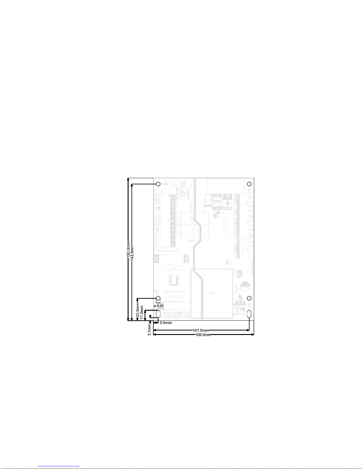
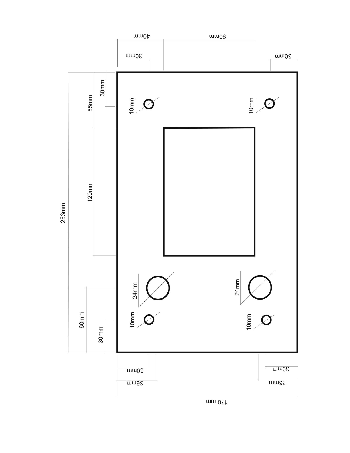
Install the controller into drive. All dimensions are in the
Picture 1. After correct installation continue with
electrical connection.
The manufacturer will not be liable for losses and
disruption in work resulting from non-observance of this
installation, operation manual and applicable regulations.
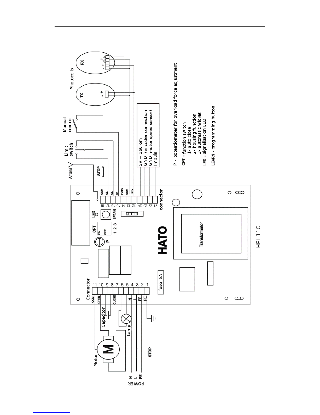
2.1 Limit switches connection
At first connect limit switches to the controller inputs
marked as (16,17,18). Check the gate condition: the gate
should not swing too much, it should move easily and
smoothly between limit positions. If necessary adjust
placements of magnetic parts.
16 (OL) —open limit,
17 (CL) — close limit,
18 (COM) — common, (white wire)
The controller cooperates with Normally Open or Normally
Closed limit switches. To change type of limit switches
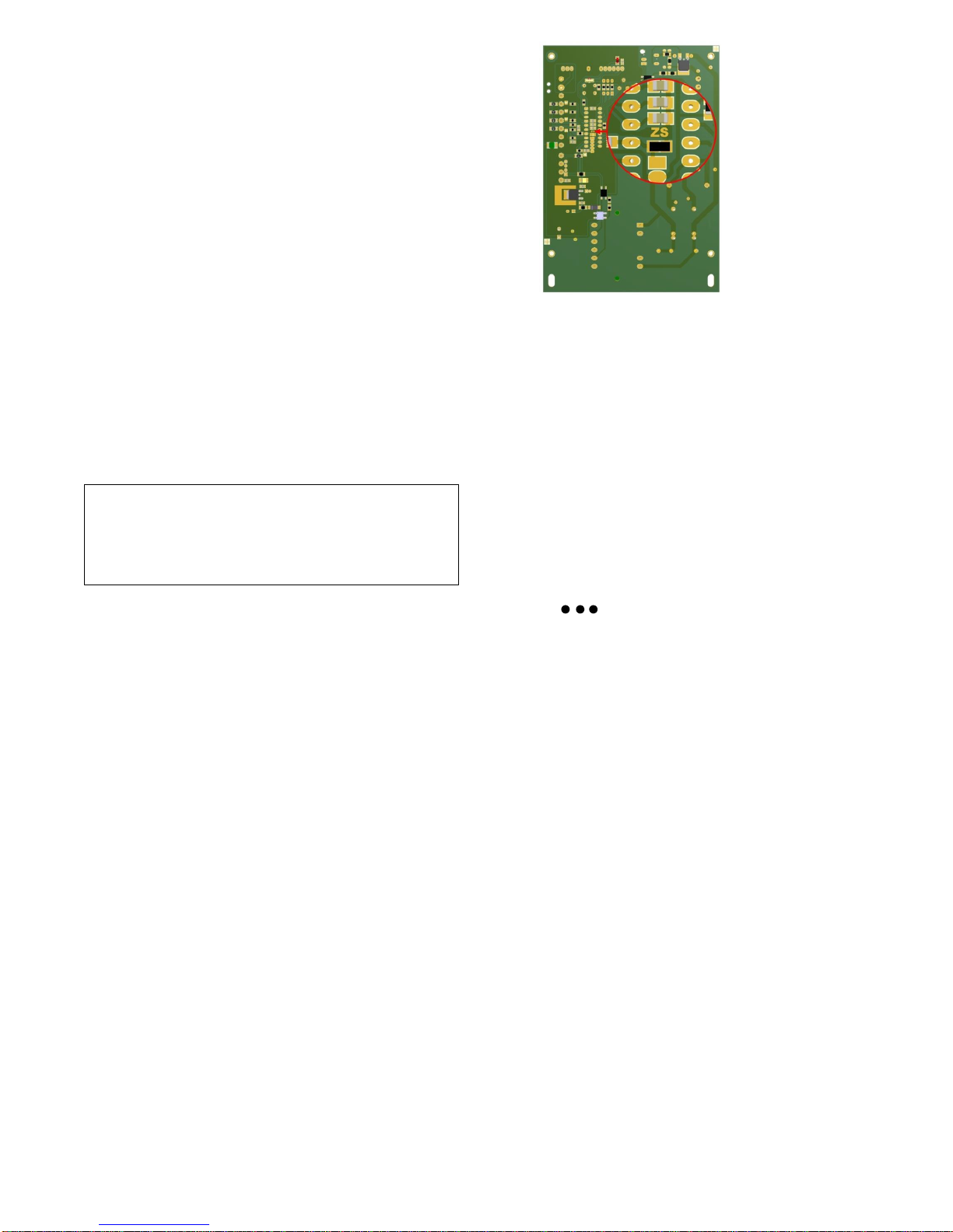
solder the ZS jumper on PCB. With soldered jumper
version marked as NO cooperates with NC type switches
and version marked as NC cooperates with NO switches.
If you have cotroller without encoder input - skip point 2.2.
2.2 Encoder connection
Motor encoder must be connected to the inputs marked as
"ENCODER" (Pic.2)(21,22,23,24).
Connect the encoder wires to the plug according to wiring
diagram description. The controller uses encoder impulses
to calculate applicable force. Uncorrect connection may
cause unproper operation and hazardous situation to healt
and life.
21 - ─ ─ - encoder signal
22 - + + + - GND
23 - ─x─ - GND
24 - - supply (+5V)
Enkoder parameters: 717 impulses per second (speed
1450rpm)
2.3 Photocell connection
Photocell barrier is a necessary safety element which
must be connected to the controller. It increases safety
and prevents a gate wing from hitting a car, a person or an
object which are within the photocells’ range. In the
controller without encoder input it is necessary to connect
gate optical curtain or other safety elements preventing
from accidentally crush. It should be in series with
photocell.
12 – Photocell supply +24Vdc
13 – Photocell supply GND
13-14 –Normally Closed contact
Output (+24V) current cannot exceed < 450mA. Make
sure power consumption of all connected accesorries.
Example of photocell connection is shown on the wiring
diagram.
!
The controller uses the 230Vac voltage and
it can be installed only by qualified
personnel with relevant licences
Page 11
11
!
Mains supply must be protected by earth
leakage circuit breaker
2.4 Step-By-Step pushbutton connection
Connect the SBS pushbutton using 2x 0,5mm2 wire which
parameters are according to regulations: CEI 20-22; CEI
EN50267-2-1. Maximum distance of connection depends
on selected wire. Series resistance should not exceed
100ohms.
Connect momentary pushbutton switch to the inputs
marked as S1 (15) and COM (18).
2.5 Capacitor connection
Connect capacitor to the inputs on the left side marked as
8 i 9.
2.6 Motor connection
Connect motor’s wires to the left connector plug according
to description or wiring diagram:
11 (COM) – common
10 (OPEN) –open direction
7 (CLOSE) –close direction
1 (PE) – protective earth PE (yellow-green wire)
2.7 Signalling lamp connection
Connect signalling lamp (230Vac) to the inputs on the left
side marked as 5 (neutral – blue wire) and 6 (phase –
brown wire). Lamp power cannot exceed 15W/230V.
When used lamp with built-in flashing module before
installation switch off the flashing function in the controller
(according to 3.5 point).
2.8 Mains supply connection
Mains connection should be applied at the end of
installation. Connect mains wires to the inputs on the left
side marked as:
2 (PE) – protective ground (yellow-green wire)
3(L) – phase wire (brown wire)
4 (N) – neutral wire (blue wire)
Before first using check the correct power supply,
ground protection and wire connections. Wires
should be as short as possible. Keep control wires
away from high current wires. Avoid wires loop.
2.9 Open direction check
Set the gate manually in the middle position. The first
command after powering up is “open”. Press the SBS or
programmed transmitter button. If drive works in closing
direction stop the motor, switch off the power supply and
switch motor’s leads connected to the inputs OPEN(10)
and CLOSE(7).
If the drive operates properly check functionality of all
connected accessories. In case of problems check wiring
connection and adjust motor force or applicable force
setting.
2.10.1 Motor power adjustment (HEL11C
version) ??
Fitted on the control unit “P” potentiometer adjusts
maximum motor power. Take great care when adjusting
the power as this may affect the level of safety of the
automatic system. Measure the force applied to the
gate and compare it with regulatory values.
2.10.2 Applicable force adjustment -(HEL11C)
The controller uses encoder impulses to calculate
applicable force. To adjust the sensivity of the controller
use the “P” potentiometer. In minus direction sensitivity
decreases, in plus direction sensitivity increases.
Adjustment must be carried out according to
applicable regulations.
2.11 Optional STOP button connection
Connect external normally closed switch according to
wiring diagram.
3. Settings and programming
3.1 Autoclose
In the autoclose operation mode, an opening manoeuvre
is followed by a pause and then an automatic closing
manoeuvre. The closing time is determined by the delay in
turning off the light. It is activated when the OPT1
(DIPSWITCH) micro-switch is put to ON. When the
Auto-close function is active, the principle of light
operation is different: the light is slowly flashing when the
gate is opening, the light is on when the gate stays open,
and is flashing during automatic closing. When the
gate stops, the light is off. The Auto-close function
Disconnect the power supply before checking
wire connection.
!
The controller uses the 230Vac voltage and
it can be installed only by qualified
personnel with relevant licences
Page 12

12
necessitates photocells to ensure user safety (to prevent
gate from closing when an obstacle is within its range!). in
addition, the photocells will reduce the opening time. The
controller will detect the passage of a vehicle and will
close the gate after 5 seconds. When the Auto-close
function is active, all programming procedures can be
performed only when the gate is stopped after closing.
3.2 Autoclose time setting
To program the controller use the LEARN button and the
LED on the controller board. Press the LEARN button less
than 3s, the LED will light up. Then, by pressing the same
button you can set the delay time. One keystroke
corresponds to 15 seconds, (e.g. 4 keystrokes mean 1
minute; the LED dims at each keystroke). When you have
finished programming, the processor will automatically
save the settings after 3s, flash the LED three times and
return to normal operation.
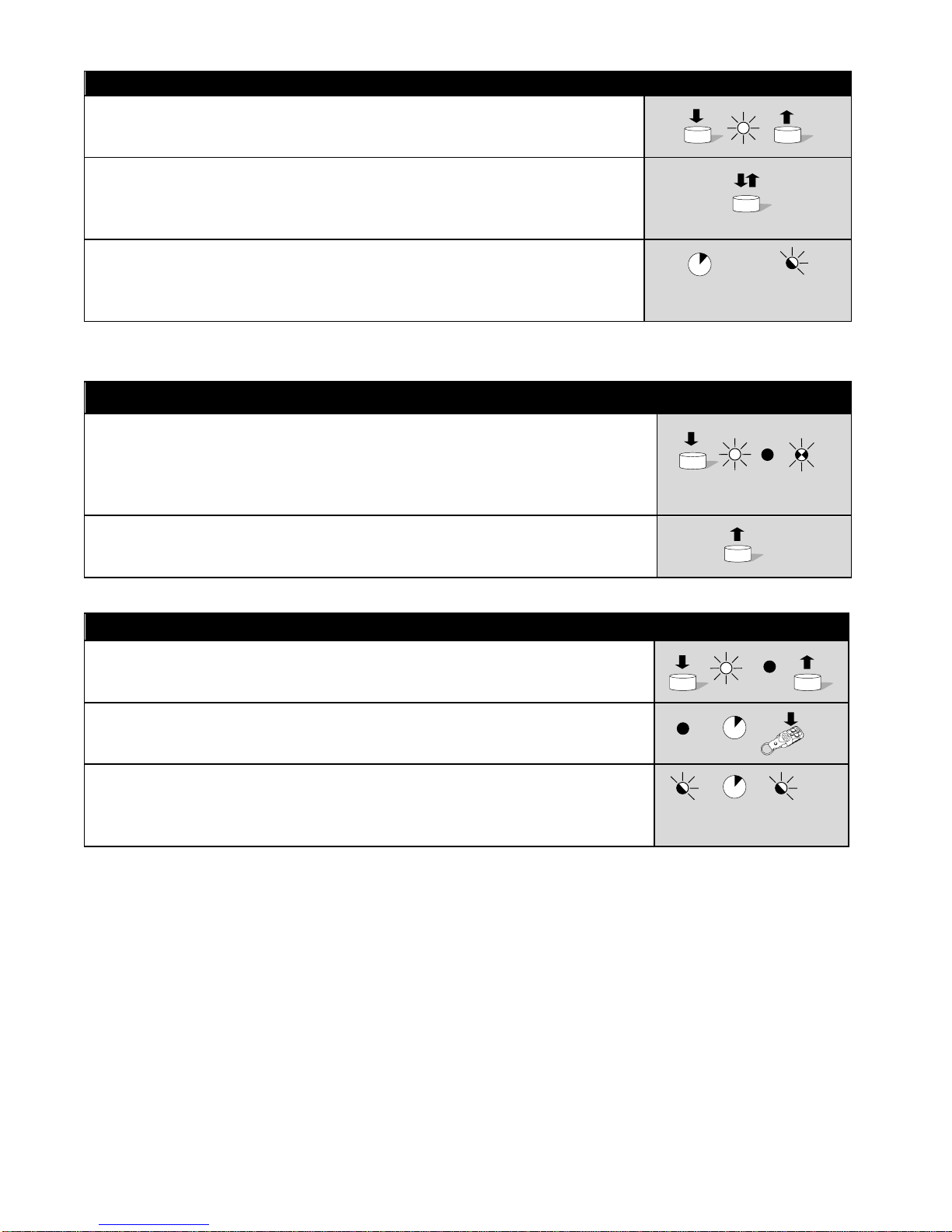
Example of autoclose time setting shows Tab1.1
3.3 Open only function
Open-only function facilitates communication
through entry-exit and guarantees that a third party will not
close or stop the gate in the least opportune moment.
Photocells are necessary for safety. It works only with the
Auto-close function and is activated by putting the OPT1
and OPT2 micro-switches to ON. A command from the
remote or from manual control will tell the controller to
open the gate in each case, and then the gate will be
closed by the Auto-close function.
3.4 Automatic wicket
It is activated when the OPT3 (DIPSWITCH) micro-switch
is put to ON. In the automatic wicket operation mode,
when the controller will detect the passage of a vehicle or
person (photocell) during opening the gate will stop. To
close the gate push the SBS or programmed transmitter’s
button. When autoclose function is also activated when
the controller will detect passage the gate will stop and
after 5s will close.
3.5 Signalling lamp
It can work in two modes. In the first mode, as warning
signals when the gate is moving. In the second one, as an
auxiliary lighting of a vehicle or garage with delayed off. In
the second mode the lamp is on when gate is moving.
To switch off second mode put the OPT1 (DIPSWITCH)
micro-switch to OFF. Press the LEARN button less than 3s,
the LED will light up. Wait 3s, the controller will flash the
LED tree times and return to normal operation.
4. Transmitters deleting and
programming
4.1 Deleting all transmitters
Press the LEARN button and hold, the LED will light up,
go out and then it will start to flash. Release the button.
The deleting procedure is completed. We recommend that
this procedure is performed right after installation.
4.2 Transmitters programming
You can program up to 40 remote controls with Keeloq’s
rolling code. Each remote must be programmed
separately. Press LEARN and hold until the LED lights up
and goes out. Release the button. Now you have 10
seconds to press a selected button in the remote control.
When the LED flashes three times, the learning process
has been completed successfully. If you wish to program
more transmitters, after three LED flashes you have next
10 seconds to program the second remote, etc. A single
LED flash means that the learning process is finished.
When you have programmed 40 remotes, the memory is
full and the LED will flash only two times and will return to
the normal operation. If the memory is full, check if you
really use 40 remotes. If you use fewer than 40 remotes,
clear the memory and reprogram all remotes, and when
you use more than 40 remotes use an additional module
eL3 which will increase the number of transmitters to 64.
When the learning error occurs, repeat the programming
and if this does not help either use another remote in good
working order. If you still fail, contact the authorized
service.
4.3 Remote transmitter programming
It is possible to program new transmitter using
four-channel earlier programmed transmitter. The gate
must be fully open. Push the C and D buttons of the
programmed transmitter for 5s. The signalling lamp will
light up. Now you have 5 seconds to press a selected
button in the new remote controller. When the lamp
flashes three times, the learning process has been
completed successfully. A single LED flash means that the
learning process is finished.
Page 13
13
Tab.1.1. Autoclose time setting
(e.g.)
1. Press the LEARN button. The LED will light up. Release the button.
2. Then, by pressing the same button you can set the delay time. One keystroke
corresponds to 15 seconds, (e.g. 4 keystrokes mean 1 minute; the LED dims at
each keystroke).
4x
3. Wait 3s, the controller flash the LED three times and return to normal operation.
3s
3x
Tab.1.2 Deleting all transmitters
1. Press the LEARN button and hold, the LED will light up, go out and then it will start
to flash. We recommend that this procedure is performed right after installation.
5x
2. Release the button. The deleting procedure is completed.
Tab.1.3 Tranmistters programming
1. Press LEARN and hold until the LED lights up and goes out. Release the button.
2. Now you have 10 seconds to press a selected button in the remote control. When
the LED flashes three times, the learning process has been completed successfully.
10s
3. When the LED flashes three times, the learning process has been completed
successfully. A single LED flash means that the learning process is finished.
3x 10s
1x
Page 14
14
5. Technical specification:
Power supply: AC 230V, 50Hz
Curren consumption in standby: < 25mA AC
Powe consumption in standby: < 10 W
Transmitters range: <200m
Frequency: 433,92MHz
Transmitters type:
Version HATO Keeloq
Transmitters memory: 40 pcs
Autoclose max time: 5s - 10min
Operation max time: 120 sec.
Operating temperature: -20ºC +70ºC
Fuse type: 5A/230V, ø5x20
6. Dimension
Page 15
Page 16
HATO 400Y SLIDING GATE OPERATOR USER’S MANUAL
16
7. Controller wiring diagram
Picture 2
Page 17

HATO 400Y SLIDING GATE OPERATOR USER’S MANUAL
17
DISTRIBUTOR/SALESMAN
Hato Polska S.C
Tomasz Słodkowski – Harmeet Singh
ul. Tunelowa 57
40-676 Katowice
POLAND
Warehouse/sales/service
ul. Żeromskiego 1
41-205 Sosnowiec
tel. 032/ 785-25-42
www.hato.com.pl
 Loading...