

Page 1

™, LLC
“Malicious Intent Code”
Instruction Manual
Features:
• Designed for all DM4, DM5, and
DMC markers. The Malicious
Intent Code chip also works with all
Lucky™ Un1 Boards and various
other boards which accept DM
chips.
• Includes seven firing modes: NPPL
Semi, PSP, Auto Response, Fast
Ramping, Discrete Ramping, NPPL
Breakout, and PSP Breakout.
• 15 bps compatible!
• Blazing fast trigger logic! The
Malicious Intent Code constantly
monitors the trigger switch to
ensure that all pulled shots register
and are processed. There is simply
not a more responsive software
upgrade available.
• ABS features add to the marker’s
dwell to eliminate that pesky first
shot drop-off.
• Anti-mechanical bounce (AMB)
algorithms solve the problem of
physical switch bounce. No need
to worry when the refs pull that old
slow trigger pull trick on your gun.
• The Malicious Intent Code sports
the most power efficient software in
the industry. The days of perpetual
battery changing are over!
• A “forced shot” feature allows the
user to fire the marker even when
the eyes are enabled.
• Instant on feature. After all, you
wanna play now!
• Tournament lock feature allows the
user to “lock out” the programming
mode in order to meet specific
field/tournament guidelines.
Installation:
Note: These installation instructions are
for DM markers. Lucky™ Un1 Board
installation may differ slightly. MAKE
SURE THE MARKER IS NOT
CONNECTED TO AN AIR SOURCE AND
DOES NOT HAVE PAINTBALLS IN THE
BREACH DURING INSTALLATION!!!!!!
1. Remove the screws that secure the
grips. This will expose the board.
2. Remove your existing microchip.
To do this, take a small Allen
Wrench and pry up each corner in
small increments until the chip is
ready to be removed by hand. Be
very careful! You can bend your
existing chip’s pins during this
process.
3. Install your new Hater Chip into the
socket. The half-moon on the edge
of the Hater Chip should align with
the corresponding half-moon in the
socket. For DM guns, the halfmoon on the Hater Chip should
point towards the trigger frame. Be
careful not to bend or break the
pins!
4. Replace grips.
5. Enter you desired programming.
Power:
The Hater Chip comes equipped with an
Instant On feature. Simply press the
power button and your marker will
instantly power on. To turn the marker off,
press and hold the power button until the
LED display goes blank.
Eye Sensor Operation:
When the Hater Chip is powered on, the
eyes are enabled by default. To disable
the eyes, press and hold the eye button
on your marker. When the eyes are
bypassed, the ROF is capped at 20 cycles
per second. When paint and air are
added to the marker and the ROF cap is
disabled, the marker will shoot as fast as
your loader can feed.
LED Representation:
Solid Blue Eyes on; Paint in breach.
Blinking Blue Eyes on w/ blocked/dirty error.
Solid Red Eyes on; No paint in breach.
Blinking Red Eyes disabled.
Page 2
Programming
The fourth dip switch must be in the
UP/ON position in order to enter the
programming menu. If the fourth dip
switch is off, “tournament lock” will be
enabled and the user will be unable to
program the marker.
To enter the programming menu, hold the
trigger down and THEN turn the marker
on. The LED will inform the user that the
programming mode has been accessed
by flashing several colors rapidly.
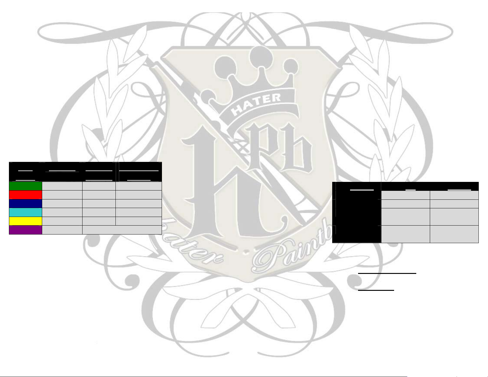
LED
Color
Green Debounce 5 ms 0-50 ms
Red Dwell 18 ms 1-35 ms
Blue Max ROF 20 bps 11-20 bps
Teal AMB 10 ms 1-40 ms
Yellow Eye Delay 1 ms 0.5-20 ms
Purple Fire Mode See Firing Modes
Pulling and releasing the trigger will allow the
user to toggle through the different
programming options. Once the desired
setting/LED color is reached, pull and hold
the trigger to select that setting. The LED will
then go blank. Once the LED goes blank,
pull the trigger for the desired setting. For
example, if the user wishes to set the
debounce to 2, he or she must pull the trigger
two times. The software will indicate that the
new value has successfully been entered by
rapidly flashing the LED through a spectrum
Setting Default
Setting
Adjustable
Range
of colors. To exit the programming menu,
turn the gun off and back on.
Programming Examples:
To set the firing mode to PSP mode.
1. Turn the marker off.
2. Hold the trigger down; then turn the
marker on. Once the LED flashes many
colors, release the trigger.
3. Tap the trigger until the LED turns purple.
4. Hold down the trigger until the LED goes
blank.
5. Tap the trigger two times.
6. Once the LED flashes many colors, turn
the marker off.
To set the eye delay to 5 ms.
1. Turn the marker off.
2. Hold the trigger down; then turn the
marker on. Once the LED flashes many
colors, release the trigger.
3. Tap the trigger until the LED turns yellow.
4. Hold down the trigger until the LED goes
blank.
5. Tap the trigger ten times. (Eye delay is
measured in ½ ms increments. Ten
trigger pulls = a 5 ms eye delay.)
6. Once the LED flashes many colors, turn
the marker off.
To set the max ROF to 15 bps.
1. Turn the marker off.
2. Make sure the 3
UP/ON position.
rd
dipswitch is in the
3. Hold the trigger down; then turn the
marker on. Once the LED flashes many
colors, release the trigger.
4. Tap the trigger until the LED turns blue.
5. Hold down the trigger until the LED goes
blank.
6. Tap the trigger five times. (Max ROF’s
lowest value is 11bps. Therefore, 1 pull =
11 bps, 5 pulls = a 15bps cap.)
7. Once the LED flashes many colors, turn
the marker off.
Programming Note: All settings are
incremented from the lowest value in the
range in 1 bps or 1 ms increments. Eye
delay, however, is incremented in ½ ms
increments.
Dip Switch Settings:
Switch UP DOWN
1
2
3
ABS On ABS Off
AMB On AMB Off
ROF Cap On Unlimited
ROF
4
Programming
Mode
Tournament
Lock
Firing Modes:
1. Semi Auto/NPPL – 1 trigger pull = 1
shot fired.
2. PSP Mode – The first three shots are
semi auto. On the 4th shot, the gun
will ramp to the max ROF. This
ramping will continue as long as the
trigger is being pulled. After a one
second delay of trigger inactivity, the 3
shots semi-auto sequence will restart.
Page 3

3. Auto Response Mode – The gun will
fire once when the trigger is pulled and
once when the trigger is released.
4. Fast Ramping – Uses a parabolic
algorithm that ramps proportionately to
trigger pull speed. As the user pulls
the trigger faster, the software adds
more shots. This is a fast, but smooth
ramping mode.
5. Discrete Ramping – Uses a mild
parabolic algorithm with a high
activation point. This mode is a “quick
semi-auto” mode and the ramping is
virtually undetectable by pull tests.
6. Semi-Auto Breakout –
a. First shot full auto
b. The next 150 pulls use “fast
ramping”
c. Semi-Auto/NPPL legal. (The
151st pull will be NPPL legal.)
7. PSP Breakout –
a. First Shot Full Auto
b. The next 150 pulls are PSP
mode + 3 bps.
c. PSP legal. (The 151st pull will
be PSP legal).
Definitions:
Debounce – The Hater Chip debounce
algorithm assists in eliminating unwanted
shots caused by “trigger noise,” while
simultaneously ensuring that every pull is
read. If the marker has intermittent or
continuous “full auto” like fire, increase the
debounce setting.
Dwell – Dwell is the amount of time that the
solenoid is “charged.” A dwell that is too low
may result in a gun that doesn’t fire, is
inconsistent and/or had drop off. If the dwell
is set too high, the overall rate of fire will
decrease and the marker may become less
air efficient. Note: If using the Hater Chip
in a Lucky™ Un1 or similar board, the
user must set the dwell accordingly
before using. Some markers, such as the
Ego, run at a lower dwell than the default
dwell setting on the Hater Chip.
Eye Delay – The eye delay is the amount of
time the gun will pause after sensing a ball
before it will fire. The stock eye delay of 1 ms
should suit most markers which use a force
fed loader. If the user experiences chopping
while using an agitated loader, the eye delay
should be set to 4 ms or higher. The higher
the eye delay, the slower the marker.
ABS – The Anti-Bolt Stick feature increases
the dwell of the marker’s first shot after a
period of inactivity. The ABS feature assists
in eliminating first shot drop-off. To turn ABS
on, set the first dip switch to the ON position.
AMB – Anti-Mechanical Bounce feature
assists the user in eliminating mechanical
bounce. Mechanical bounce is caused by the
marker recoiling. Increasing the AMB will
assist in tuning your marker to pass those
pesky slow pull tests.
Max ROF – This feature allows the user to
cap the maximum rate of fire of their marker.
Some leagues, such as the PSP, require that
guns not exceed 15 bps. The Max ROF
feature is adjustable from 11-20 bps in 1 bps
increments. Note: The user must set both
the fire mode to PSP AND the ROF Cap to
15 bps to comply with PSP rules.
Forced Shot – If the eyes are enabled, but
the breach is empty, the user may force a
shot by holding in the trigger for
approximately one second. This feature is
useful in the event that a ball has been
pushed into the detents and is unreadable by
the eyes. A forced shot will clear the breach
and load the next paintball as normal.
HATER
PAINTBALL
HATER PAINTBALL LLC
PO Box 1241
Crawfordsville, IN 47933
United States
317-354-5201 (p)
317-203-0719 (f)
info@haterpaintball.com
www.haterpaintball.com
 Loading...